Home → Balancing Theory & Standards
Rotor Balancing Theory: ISO Norms, G Grades, Formulas and Calculations
Everything the standards actually say, with the math shown: what unbalance is in plain words, the centrifugal-force formula, static vs dynamic unbalance, RMS vibration velocity, ISO 10816 vibration zones (including pumps), ISO 1940 / ISO 21940-11 balance quality grades with the permissible-residual-unbalance calculation, mm/s ↔ dB conversion, natural frequencies and resonance — and how each of these looks on the screen of a real field balancing instrument.







- Rotor unbalance in simple terms
- Centrifugal force from unbalance
- Static vs dynamic unbalance
- How unbalance shortens bearing life
- RMS vibration velocity — what it is
- ISO 10816 vibration norms (incl. pumps)
- G grades table (ISO 1940 / 21940-11)
- Permissible residual unbalance: the calculation
- Natural frequency and resonance
- Converting mm/s to dB
- FAQ
1. What Is Rotor Unbalance, in Simple Terms
Ideally, a rotor’s mass is distributed so that its center of mass lies exactly on the axis of rotation. In reality it never quite does: casting porosity, machining tolerances, welded-on repairs, worn or replaced blades, caked dirt, a key sitting in a keyway — all shift a few grams to one side. That mass offset is unbalance.
While the rotor stands still, unbalance is invisible. As soon as it spins, the offset mass is forced to travel in a circle, and by Newton’s laws it pulls the shaft outward — once per revolution, always toward the “heavy spot”. The bearings receive a rotating force; the housing receives vibration at exactly the rotation frequency (the 1× component). That single sentence explains most of what a balancing instrument does: it measures how big the once-per-revolution pull is (amplitude) and where the heavy spot points (phase).
Unbalance is quantified as mass times its radius:
U — unbalance [g·mm]; m — offset mass [g]; r — radius where it sits [mm]. 10 g at 100 mm = 1,000 g·mm — exactly as harmful as 20 g at 50 mm.
Dividing U by the rotor mass gives the specific unbalance e = U/M [g·mm/kg = µm] — which is nothing other than the distance between the center of mass and the axis of rotation. This little quantity is the bridge to the ISO grades in section 7: a “well-balanced” industrial rotor typically has its center of mass within a few dozen microns of the axis.
2. The Centrifugal Force from Unbalance — Formula and Worked Numbers
The rotating pull that unbalance creates is ordinary centrifugal force:
F — force [N]; m — unbalance mass [kg]; r — radius [m]; U — unbalance [kg·m]; ω — angular speed [rad/s]; n — rotor speed [rpm].
The part people underestimate is the square on ω. Take a modest unbalance of 100 g·mm (10 g sitting at 10 mm, or 1 g at 100 mm) and watch what speed does to it:
| Rotor speed | ω | Centrifugal force from 100 g·mm | Equivalent static weight |
|---|---|---|---|
| 500 rpm | 52.4 rad/s | 0.27 N | ~28 g |
| 1,500 rpm | 157 rad/s | 2.5 N | ~0.25 kg |
| 3,000 rpm | 314 rad/s | 9.9 N | ~1 kg |
| 6,000 rpm | 628 rad/s | 39.4 N | ~4 kg |
| 12,000 rpm | 1,257 rad/s | 158 N | ~16 kg |
A more industrial example: a repair shop welds a new hammer bracket onto a mulcher drum and leaves it 50 g heavy at a radius of 200 mm — that is U = 10,000 g·mm. At the working 1,500 rpm the drum’s bearings now carry an extra rotating force of F = 0.01 kg·m × 157² ≈ 246 N ≈ 25 kg — a bag of cement swinging around the shaft 25 times per second. At 2,000 rpm the same mistake pulls with ~44 kg.
Two practical consequences follow directly from the ω² law:
- Tolerances tighten with speed. The same residual unbalance that is harmless in a 500-rpm crusher is destructive in a 12,000-rpm spindle — which is exactly how the G grades are constructed;
- “It only vibrates at full speed” is expected physics, not a mystery: at half speed the force is a quarter. (If vibration jumps disproportionately in a narrow RPM band, that is a different phenomenon — resonance.)
3. Static vs Dynamic Unbalance — the Difference That Decides One Plane or Two
Unbalance comes in two elementary forms, and the difference is not academic: it decides whether one correction weight is enough or two planes are required.
- Static unbalance — the heavy spot is effectively at one axial location; the center of mass is shifted sideways. On free supports the stopped rotor rolls heavy-side-down by itself (hence “static” — you can find it without spinning). One weight in one plane corrects it (static / single-plane balancing).
- Couple / dynamic unbalance — two equal heavy spots at opposite ends of the rotor, 180° apart. At rest they cancel: the rotor is statically balanced and will not roll. In rotation each end pulls its own way, half a turn out of step — the rotor wobbles, the supports vibrate in opposite phase. This couple unbalance is detectable only in rotation and correctable only with weights in two planes. Real rotors carry a mix of both forms, which is why long rotors are balanced in two planes as one combined calculation — the full method is covered in Dynamic Balancing Explained.
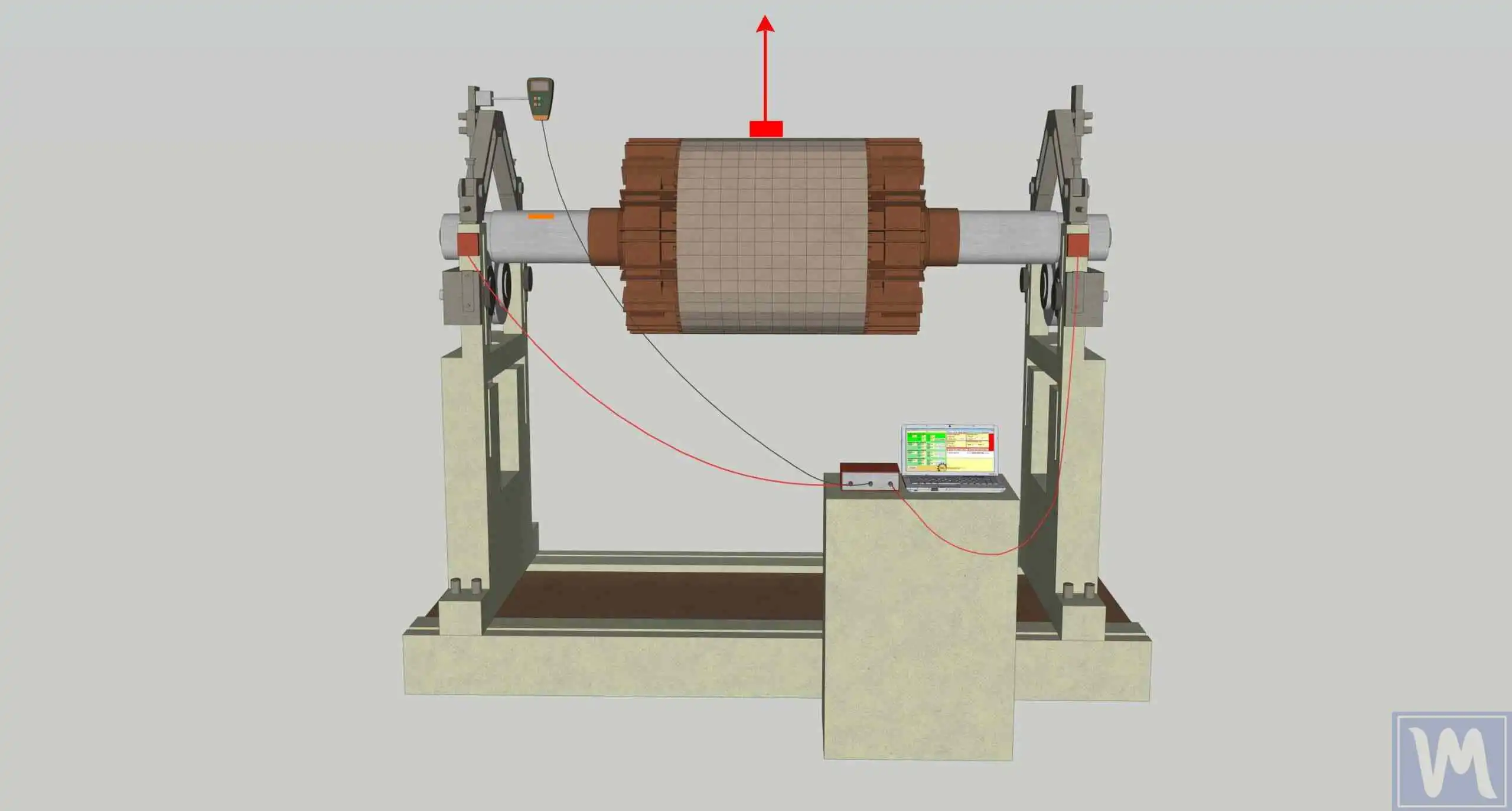
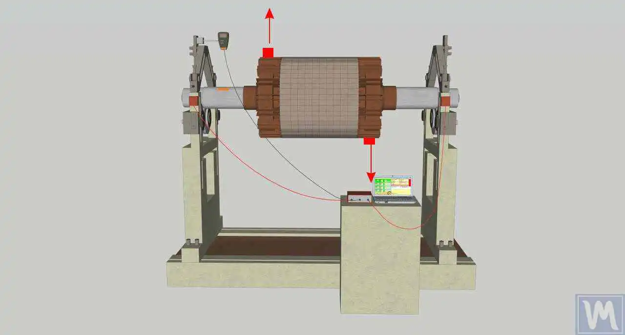
| Static unbalance | Dynamic (couple) unbalance | |
|---|---|---|
| Detectable at rest? | Yes — rotor rolls heavy-side down | No — appears only in rotation |
| Support vibration | Both supports in phase | Supports out of phase (rotor “wobbles”) |
| Correction | 1 weight, 1 plane | 2 weights, 2 planes, solved together |
| Rule of thumb | Rotor width < ~1/2 of diameter (in practice 1/3) → one plane usually suffices; longer → two planes (ISO 21940-11) | |
4. What Unbalance Does to Bearings: The Cubic Law of Life
The centrifugal force from section 2 does not vanish — it lands in the bearings as an additional rotating load, added on top of the weight and process loads the bearing was sized for. Rolling-bearing fatigue life follows the classic rating equation:
C — dynamic load rating of the bearing; P — equivalent dynamic load actually applied.
Because load enters cubed (or worse), moderate-looking unbalance forces translate into dramatic life loss:
| Extra dynamic load from unbalance | Remaining bearing life (ball, p = 3) |
|---|---|
| +10 % | ≈ 75 % |
| +26 % | ≈ 50 % |
| +50 % | ≈ 30 % |
| +100 % (load doubled) | ≈ 12 % |
In the mulcher example above, the forgotten 50 g at 200 mm added ~250 N of rotating load. For a drum bearing loaded at, say, 1 kN that is +25% — life roughly halved by one sloppy repair. And bearings are only the first victim; the same shaking loosens bolts, works cracks open in welds and housings, wears couplings and belts, and blurs the machining finish of machine tools. That chain — unbalance → force → fatigue — is why balancing is maintenance, not cosmetics.
5. RMS Vibration Velocity: What Is Actually Being Measured
Vibration can be described by displacement (µm), velocity (mm/s) or acceleration (m/s²). Machine-condition standards settled on vibration velocity, because it weighs the destructive mid-frequency range most evenly — and specifically on its RMS value (root mean square):
RMS is the “energy average” of the signal over the measurement window — the quantity ISO 10816/20816 limits refer to.
Why RMS and not the peak? A real vibration signal is a cocktail: the 1× unbalance sine plus harmonics, bearing noise and random spikes. Peaks jump around; the RMS integrates the signal’s true energy content and repeats reliably from measurement to measurement — which is what you need to compare against a norm or a “before” value. (Peak values still matter in shock analysis; for balancing and condition assessment, RMS rules.)
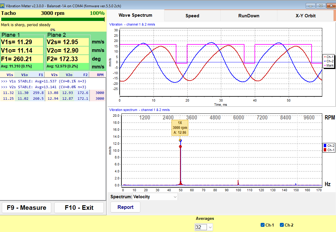
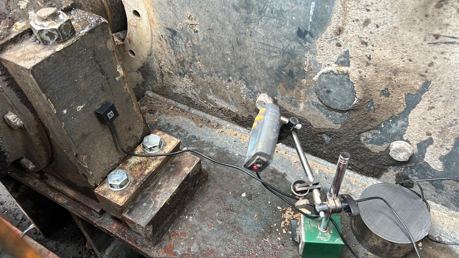
How it is measured in practice: an accelerometer on the bearing housing (radial direction, magnet mount on a clean flat spot), signal integrated to velocity, band-limited to the standard 10–1,000 Hz range, RMS computed over a few dozen averaged revolutions. In the Balanset-1A vibrometer screen you see the three numbers that matter side by side: overall RMS (all causes together), the 1× component (the part balancing can remove — with its phase), and the RPM. If overall is 6 mm/s but the 1× part is only 1 mm/s, balancing will not fix that machine — something other than unbalance is shaking it.
6. Vibration Norms per ISO 10816 / 20816 — Including Pumps
ISO 10816 (now being consolidated into ISO 20816) answers the operator’s question: “is this much vibration acceptable?” It evaluates the assembled machine by RMS vibration velocity measured on non-rotating parts (bearing housings) and sorts the result into four zones:
| Zone | Meaning | Typical guideline (medium machines) |
|---|---|---|
| A | New-machine condition | up to ~1.4 mm/s |
| B | Acceptable for unrestricted long-term operation | 1.4 – 2.8 mm/s |
| C | Unsatisfactory for long-term operation — plan correction | 2.8 – 4.5 mm/s |
| D | Vibration causing damage — act now | above 4.5 mm/s |
For pumps specifically (ISO 10816-3 Group 2: machines 15–300 kW, and ISO 10816-7 for rotodynamic pumps), the zone boundaries depend on the foundation type — rigid or flexible:
| Pump on… | Zone A/B boundary | Zone B/C boundary | Zone C/D boundary |
|---|---|---|---|
| Rigid supports (grouted baseplate) | 1.4 mm/s | 2.8 mm/s | 4.5 mm/s |
| Flexible supports (frame, spring mounts) | 2.3 mm/s | 4.5 mm/s | 7.1 mm/s |
Larger machines (>300 kW, ISO 10816-3 Group 1) get proportionally softer limits (2.3 / 4.5 / 7.1 mm/s rigid, 3.5 / 7.1 / 11 mm/s flexible). Always check the machine manufacturer’s own limit if one is stated — it overrides the generic table.
Three field rules that make the tables useful rather than academic:
- Measure at the bearings, in three directions where possible (horizontal, vertical, axial) — the norm applies to the highest reading;
- Judge the trend, not just the absolute. A pump that lived at 1.8 mm/s for years and now shows 3.4 mm/s deserves attention even though it is still “acceptable”;
- Agricultural and mobile machinery is judged softer — mulchers and mowers on their inherently flexible frames are considered fine up to ~7 mm/s; chasing pump-grade numbers there is wasted effort (details in the tolerances chapter).
7. Balance Quality Grades G — the ISO 1940 / ISO 21940-11 Table
While ISO 10816 judges the running machine, ISO 1940-1 (superseded by ISO 21940-11, content essentially unchanged) judges the rotor itself: how much residual unbalance may remain after balancing. The tolerance is expressed as a balance quality grade G, defined as the product of specific unbalance and angular speed:
e_per — permissible specific unbalance (center-of-mass offset) [mm]; ω — angular speed [rad/s]. The product is a velocity — which is why grades carry mm/s units.
The elegance of this definition: one G number covers all speeds. A rotor balanced to G 6.3 has its center of mass close enough to the axis that the unbalance-driven velocity is 6.3 mm/s — whatever its RPM. Faster rotor → ω larger → permitted offset e_per proportionally smaller. The standard grades and their conventional applications:
| Grade | Typical rotor types (per ISO 21940-11) |
|---|---|
| G 40 | Car wheels, wheel rims, drive shafts of low-speed vehicles |
| G 16 | Cardan/drive shafts, agricultural machinery rotors, crushers’ parts, individual engine components |
| G 6.3 | The industrial default: fans, blowers, pumps, general electric motors, machine parts, drums, pulleys, flywheels, centrifuges |
| G 2.5 | Gas and steam turbines, rigid turbo-generator rotors, machine-tool drives, medium/large electric motors with special requirements |
| G 1 | Grinding-machine drives, tape recorder and phonograph drives, small precision armatures |
| G 0.4 | Precision grinder spindles, gyroscopes |
What the grade means physically is easiest to feel through e_per. At 3,000 rpm (ω = 314 rad/s), grade G 6.3 permits e_per = 6.3 / 314 = 0.02 mm = 20 µm: the center of mass of a “normally balanced” 3,000-rpm rotor sits within two hundredths of a millimetre of its axis. G 1 at the same speed allows just 3 µm. This is why balancing tooling, arbors and even the tachometer-mark position are handled with such pedantry — at these offsets, everything matters.
8. Permissible Residual Unbalance: the ISO 1940 Calculation, Step by Step
The practical question every job ends with: “how many gram-millimetres may remain?” From the grade definition, one formula answers it:
G — grade [mm/s]; M — rotor mass [kg]; n — service speed [rpm]. The constant 9549 = 1000 × 60/2π converts units. For two-plane balancing the result is split between planes — commonly 50/50 for symmetric rotors.
-
Pick the grade
From the ISO 21940-11 application table above — e.g. an industrial fan impeller → G 6.3.
-
Insert mass and service speed
Fan rotor M = 80 kg, n = 3,000 rpm: U_per = 9549 × 6.3 × 80 / 3000 = ≈ 1,604 g·mm total.
-
Split between correction planes
Symmetric rotor, two planes → ≈ 802 g·mm per plane. (The same rotor balanced to agricultural grade G 16 would be allowed ≈ 2,037 g·mm per plane — grades scale linearly.)
-
Translate into grams at your radius
Correction radius 250 mm → the residual heavy spot must be under 802 / 250 ≈ 3.2 g per plane. That is the number to compare with what the instrument reports after the trim run.
No need to do this by hand at the machine: the same calculator is built into the Balanset software — enter mass, speed and grade, and the tolerance appears next to the measured residual unbalance in the results window. A free online version is here: ISO 21940-11 residual unbalance calculator.
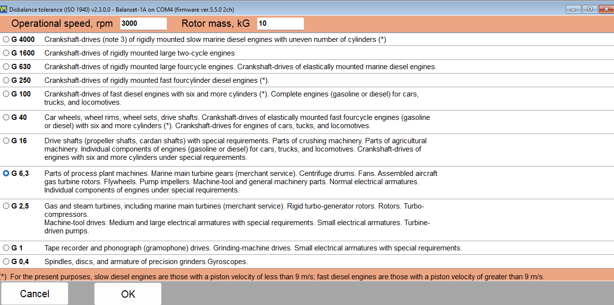
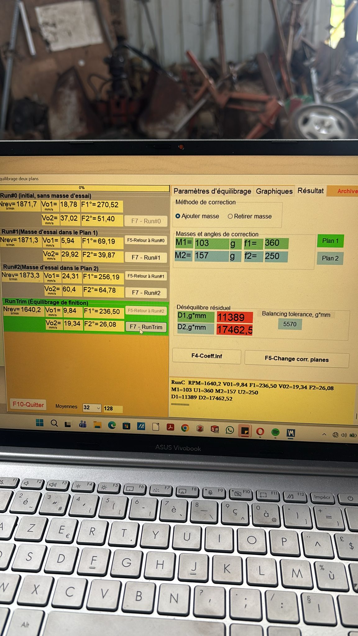
The instrument runs these calculations for you
Balanset-1A measures two channels + phase, computes correction masses by the influence-coefficient method, checks the result against ISO 21940-11 tolerances and prints the report — for €1,975, software updates free for life. The theory on this page is exactly what its screens implement.
9. Natural Frequency and Resonance — the Trap Every Balancer Meets
Every structure — rotor, supports, frame, foundation — has natural frequencies: the rates at which it “wants” to oscillate after a knock, set by its stiffness and mass (for the simplest model, f_n = (1/2π)·√(k/m)). When the rotor’s speed approaches a natural frequency, the once-per-revolution unbalance force arrives in step with the structure’s own swing, each push adding to the last. That is resonance: amplitude multiplies (limited only by damping), phase swings wildly, and the linear arithmetic that balancing relies on collapses.
How resonance betrays itself during balancing work:
- a small RPM change (50–100 rpm) changes vibration severalfold;
- the phase reading refuses to settle, or jumps when speed drifts a few rpm;
- after installing the calculated weight, vibration grows — and the next run asks for ever more mass;
- vibration is larger away from the rotor (a ladder, a guard, a cab) than at the bearings — a structural element is resonating, not the rotor.
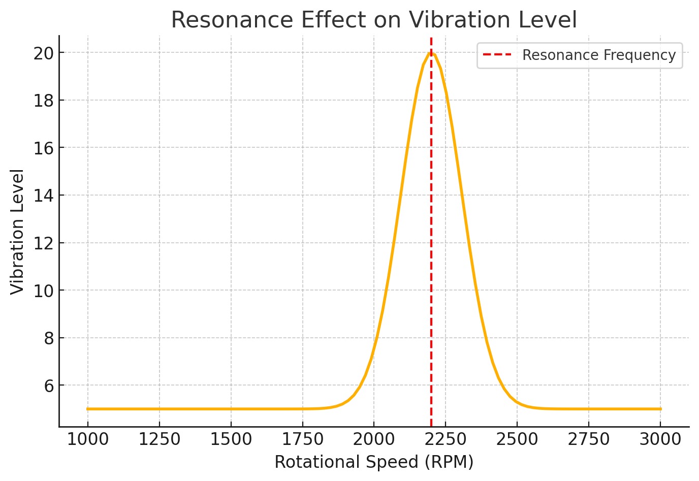
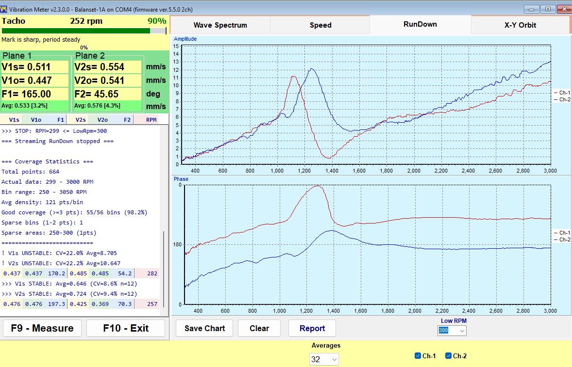
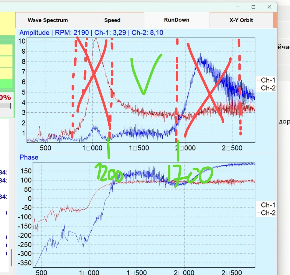
How to find the natural frequency with the instrument: the RunDown chart
The fastest field method needs no extra equipment: spin the machine up to working speed, cut the drive, and let the instrument record amplitude and phase continuously while the rotor coasts down through the whole speed range. The Balanset software plots both against RPM (the RunDown chart). Reading it takes one glance:
- each amplitude peak on the way down marks a natural frequency the rotor passed through;
- at the same speed the phase trace makes a sharp bend (~180° swing across the resonance) — the classic confirmation that it is a true resonance, not a load effect;
- the quiet valleys between peaks are your safe balancing speeds.
What to do with the knowledge:
- Balance outside resonance zones — usually clearly below the first peak or in a valley between peaks. Mulcher practice: rough-balance at 600–900 rpm, then verify at working speed;
- Keep every run of a series at the same speed (±100 rpm) — near a resonance even 2–3 rpm of drift shifts amplitude and phase noticeably;
- For test rigs and DIY stands, design the geometry deliberately: a soft (below-resonance) stand wants its natural frequency 2–3× below the balancing speed — sprung supports that visibly rock by hand achieve exactly that;
- If the working speed itself sits on a resonance, balancing is a palliative — the real fix is changing stiffness or mass (bracing the frame, different mounts) to move the natural frequency away.
10. Converting mm/s to dB (Vibration Velocity Level)
Vibration data sometimes arrives in decibels — older Eastern-European norms, some analyzers and building-vibration reports use the logarithmic scale. The conversion is a definition, not a measurement:
v — measured RMS velocity; v₀ — reference velocity. 5·10⁻⁸ m/s is the reference used in vibration-diagnostics practice (GOST/legacy ISO tradition); ISO 1683 also lists 10⁻⁹ m/s for some acoustics uses — always state the reference when quoting dB.
Handy conversions at the common reference v₀ = 5·10⁻⁸ m/s:
| RMS velocity | Level | Where you meet it |
|---|---|---|
| 0.5 mm/s | 80 dB | Excellent small machine |
| 1.0 mm/s | 86 dB | Zone A, good condition |
| 2.8 mm/s | 95 dB | Zone A/B → B/C boundary region |
| 4.5 mm/s | 99 dB | Zone C/D boundary (medium machines) |
| 7.1 mm/s | 103 dB | Flexible-support C/D boundary |
| 10 mm/s | 106 dB | Severe — damage territory |
Two rules of thumb make the scale intuitive: +6 dB = double the velocity, +20 dB = ten times the velocity. So a machine that went from 99 dB to 86 dB after balancing dropped its vibration ~4.5× — the logarithmic scale compresses big improvements into modest-looking numbers, which is exactly why service reports for customers are clearer in mm/s.
11. Frequently Asked Questions
What is rotor unbalance in simple terms?
Unbalance means the rotor’s center of mass does not lie exactly on its axis of rotation — some extra mass sits on one side. At rest it is invisible; in rotation the offset mass pulls the shaft outward once per revolution, creating a rotating centrifugal force that shakes the machine at exactly the rotation frequency (the 1× component). It is measured as mass × radius (g·mm) and corrected by adding or removing weights.
What is the formula for centrifugal force from unbalance?
F = m·r·ω² = U·ω², where U = m·r is the unbalance and ω = 2πn/60 the angular speed. The force grows with the square of RPM: 100 g·mm produces ~1 kg of rotating force at 3,000 rpm but ~16 kg at 12,000 rpm. This quadratic law is why balancing tolerances tighten as speed rises.
What is the difference between static and dynamic balancing?
Static unbalance is a single effective heavy spot: the stopped rotor rolls heavy-side-down on free supports, and one weight in one plane corrects it. Dynamic (couple) unbalance is heavy spots at opposite ends, 180° apart: the rotor is balanced at rest but wobbles in rotation, and it can only be detected while spinning and corrected with weights in two planes. Real rotors combine both, which is why long rotors are balanced in two planes as one calculation.
How does unbalance affect bearing service life?
The centrifugal force adds to the bearing’s dynamic load P, and rolling-bearing life follows L₁₀ = (C/P)³ for ball bearings — load enters cubed. Roughly: +10% load ≈ −25% life, +26% ≈ −50%, doubling the load leaves ~12% of the life. Beyond bearings, the same rotating force loosens fasteners, propagates cracks and wears couplings.
What is RMS vibration velocity and how is it measured?
RMS (root mean square) vibration velocity is the energy-average of the velocity signal in mm/s — the standard quantity of ISO 10816/20816. For a pure sine it equals 0.707 of the peak. It is measured with an accelerometer on the bearing housing (radial direction), the signal integrated to velocity in the 10–1,000 Hz band and averaged over many revolutions; two-channel instruments read both bearings simultaneously and also separate out the 1× component that balancing can remove.
What are the ISO 10816 vibration norms for pumps?
For pumps of 15–300 kW (ISO 10816-3 Group 2), the zone boundaries are 1.4 / 2.8 / 4.5 mm/s RMS on rigid supports and 2.3 / 4.5 / 7.1 mm/s on flexible supports — zone A up to the first value, zone B to the second (acceptable long-term), zone C to the third (correct soon), zone D above it (damage risk). Larger machines get proportionally higher limits; a manufacturer’s stated limit overrides the generic table.
What do the G balance quality grades in ISO 1940 mean?
A grade G (in mm/s) equals the permissible specific unbalance times the angular speed: G = e_per·ω. Common assignments: G 40 — car wheels; G 16 — cardan shafts and agricultural rotors; G 6.3 — fans, pumps, general motors and drums (the industrial default); G 2.5 — turbines and machine tools; G 1–G 0.4 — precision spindles. Because ω enters the definition, the same grade permits fewer g·mm as the speed rises.
How do I calculate permissible residual unbalance per ISO 1940?
U_per = 9549 · G · M / n, with G the grade in mm/s, M the rotor mass in kg and n the speed in rpm — the result is in g·mm, split between the two correction planes (usually 50/50). Example: 80 kg fan at 3,000 rpm, G 6.3 → 9549×6.3×80/3000 ≈ 1,604 g·mm total ≈ 802 g·mm per plane; at a 250 mm correction radius that is about 3.2 g. Online tool: the ISO 21940-11 calculator on vibromera.eu.
How do I find the natural frequency and avoid resonance when balancing?
Record a coast-down (RunDown) chart: bring the machine to speed, cut the drive, and log amplitude and phase versus falling RPM. Each amplitude peak accompanied by a sharp phase bend marks a natural frequency; the valleys between peaks are safe balancing speeds. Signs you are on a resonance: a 50–100 rpm change alters vibration severalfold, phase will not settle, and calculated weights make things worse. Balance outside the zones, or change the structure’s stiffness to move the resonance away.
How do I convert mm/s to dB for vibration?
L_v = 20·log₁₀(v/v₀) with the reference v₀ = 5·10⁻⁸ m/s used in vibration-diagnostics practice: 1 mm/s ≈ 86 dB, 4.5 mm/s ≈ 99 dB, 10 mm/s ≈ 106 dB. Remember +6 dB means double the velocity and +20 dB means ten times; and always state the reference value, since some acoustics standards use 10⁻⁹ m/s instead.

