
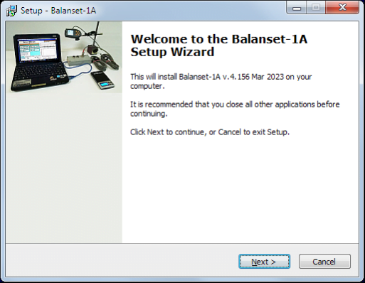
PORTABLE BALANCER ""BALANSET-1A""
ایک ڈوئل چینل پی سی پر مبنی ڈائنامک بیلنسنگ سسٹم
OPERATION MANUAL
rev. 1.56 May 2023
2023 | پرتگال، پورٹو
حفاظتی نوٹس: یہ آلہ یورپی یونین کے حفاظتی معیارات کے مطابق ہے۔ کلاس 2 لیزر پروڈکٹ۔ گھومنے والے سامان کے حفاظتی طریقہ کار پر عمل کریں۔ ذیل میں مکمل حفاظتی معلومات دیکھیں →
1. بیلنسنگ سسٹم کا جائزہ
Balanset-1A balancer پنکھے، پیسنے والے پہیوں، اسپنڈلز، کرشرز، پمپس اور دیگر گھومنے والی مشینری کے لیے سنگل اور دو ہوائی جہاز کے متحرک توازن کی خدمات فراہم کرتا ہے۔
Balanset-1A بیلنسر میں دو وائبروسینسرز (ایکسلرومیٹر)، لیزر فیز سینسر (ٹیکومیٹر)، 2-چینل یو ایس بی انٹرفیس یونٹ پری ایمپلیفائرز، انٹیگریٹرز اور اے ڈی سی ایکوزیشن ماڈیول اور ونڈوز پر مبنی بیلنسنگ سوفٹ ویئر شامل ہیں۔ Balanset-1A کو نوٹ بک یا دیگر ونڈوز (WinXP...Win11, 32 یا 64bit) ہم آہنگ پی سی کی ضرورت ہے۔.
Balancing software provides the correct balancing solution for single-plane and two-plane balancing automatically. Balanset-1A is simple to use for non-vibration experts.
All balancing results saved in archive and can be used to create the reports.
کلیدی خصوصیات
استعمال میں آسان
- • یوزر سلیکٹ ایبل ٹرائل ماس
- • آزمائشی بڑے پیمانے پر درستگی پاپ اپ
- • دستی ڈیٹا ان پٹ
پیمائش کی صلاحیتیں۔
- • RPM، طول و عرض اور مرحلہ
- • FFT سپیکٹرم تجزیہ
- • ویوفارم اور سپیکٹرم ڈسپلے
- • دوہری چینل بیک وقت ڈیٹا
اعلی درجے کے افعال
- • محفوظ کردہ اثر و رسوخ کے گتانک
- ٹرم بیلنسنگ
- • مینڈریل سنکیتی کیلک۔.
- • ISO 1940 رواداری کیلک۔.
ڈیٹا مینجمنٹ
- • لامحدود بیلنسنگ ڈیٹا اسٹوریج
- • وائبریشن ویوفارم اسٹوریج
- • آرکائیو اور رپورٹس
کیلکولیشن ٹولز
- • تقسیم وزن کا حساب کتاب
- • ڈرل کیلکولیشن
- • اصلاحی طیاروں کو تبدیل کرنا
- • پولر گراف کا تصور
تجزیہ کے اختیارات
- • آزمائشی وزن کو ہٹا دیں یا چھوڑ دیں۔
- • رن ڈاؤن چارٹس (تجرباتی)
2. SPECIFICATION
| پیرامیٹر | تفصیلات |
|---|---|
| Measurement range of the root-mean-square value (RMS) of the vibration velocity, mm/sec (for 1x vibration) | from 0.02 to 100 |
| The frequency range of the RMS measurement of the vibration velocity, Hz | 5 سے 550 تک |
| Number of the correction planes | 1 or 2 |
| Range of the frequency of rotation measurement, rpm | 100 - 100000 |
| Range of the vibration phase measurement, angular degrees | from 0 to 360 |
| Error of the vibration phase measurement, angular degrees | ± 1 |
| RMS کمپن کی رفتار کی پیمائش کی درستگی | ±(0.1 + 0.1×Vماپا) ملی میٹر/سیکنڈ |
| گردش کی فریکوئنسی کی پیمائش کی درستگی | ±(1 + 0.005×Nماپا) rpm |
| ناکامیوں کے درمیان اوسط وقت (MTBF)، گھنٹے، منٹ | 1000 |
| اوسط سروس کی زندگی، سال، منٹ | 6 |
| طول و عرض (سخت صورت میں)، سینٹی میٹر | 39*33*13 |
| ماس، کلو | <5 |
| وائبریٹر سینسر کے مجموعی طول و عرض، ملی میٹر، زیادہ سے زیادہ | 25*25*20 |
| وائبریٹر سینسر کا ماس، کلو، زیادہ سے زیادہ | 0.04 |
|
آپریٹنگ حالات: - درجہ حرارت کی حد: 5 ° C سے 50 ° C تک - رشتہ دار نمی: <85%، غیر سیر شدہ - مضبوط برقی مقناطیسی میدان اور مضبوط اثر کے بغیر |
|
3. PACKAGE
Balanset-1A بیلنسر میں دو سنگل ایکسس ایکسلرومیٹر، لیزر فیز ریفرنس مارکر (ڈیجیٹل ٹیکومیٹر)، پری ایمپلیفائرز کے ساتھ 2 چینل یو ایس بی انٹرفیس یونٹ، انٹیگریٹرز اور ADC ایکوزیشن ماڈیول اور ونڈوز پر مبنی بیلنسنگ سوفٹ ویئر شامل ہیں۔
ڈیلیوری سیٹ
| Description | Number | Note |
|---|---|---|
| USB interface unit | 1 | |
| Laser phase reference marker (tachometer) | 1 | |
| سنگل محور ایکسلرومیٹر | 2 | |
| Magnetic stand | 1 | |
| Digital scales | 1 | |
| Hard case for transportation | 1 | |
| ""Balanset-1A"۔ صارف کا دستی۔. | 1 | |
| Flash disk with balancing software | 1 |
4. BALANCE PRINCIPLES
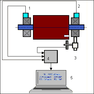
4.1. ""Balanset-1A" میں (تصویر 4.1) USB انٹرفیس یونٹ شامل ہے۔ (1)، دو ایکسلرومیٹر (2) and (3)، مرحلے کا حوالہ مارکر (4) اور پورٹیبل پی سی (فراہم نہیں کیا گیا) (5).
ڈیلیوری سیٹ میں مقناطیسی اسٹینڈ بھی شامل ہے۔ (6) فیز ریفرنس مارکر اور ڈیجیٹل ترازو کو بڑھانے کے لیے استعمال کیا جاتا ہے۔ 7.
X1 and X2 connectors intended for connection of the vibration sensors respectively to 1 and 2 measuring channels, and the X3 connector used for connection of the phase reference marker.
The USB cable provides power supply and connection of the USB interface unit to the computer.

تصویر 4.1۔ "Balanset-1A" کا ڈیلیوری سیٹ"
مکینیکل کمپن کمپن سینسر کے آؤٹ پٹ پر کمپن ایکسلریشن کے متناسب برقی سگنل کا سبب بنتی ہے۔ ADC ماڈیول سے ڈیجیٹل سگنلز USB کے ذریعے پورٹیبل پی سی میں منتقل ہوتے ہیں۔ (5). فیز ریفرنس مارکر پلس سگنل تیار کرتا ہے جو گردش کی فریکوئنسی اور کمپن فیز اینگل کا حساب لگانے کے لیے استعمال ہوتا ہے۔ ونڈوز پر مبنی سافٹ ویئر سنگل پلین اور ٹو پلین بیلنسنگ، اسپیکٹرم تجزیہ، چارٹس، رپورٹس، اثر و رسوخ کی گنجائش کے ذخیرہ کے لیے حل فراہم کرتا ہے۔
5. SAFETY PRECAUTIONS
⚡ توجہ - الیکٹریکل سیفٹی
5.1. When operating on 220V electrical safety regulations must be observed. It is not allowed to repair the device when connected to 220 V.
5.2. اگر آپ آلات کو کم معیار کے AC پاور ماحول میں استعمال کرتے ہیں یا نیٹ ورک کی مداخلت کی موجودگی میں کمپیوٹر کے بیٹری پیک سے اسٹینڈ الون پاور استعمال کرنے کی سفارش کی جاتی ہے۔.
⚠️ گھومنے والے آلات کے لیے اضافی حفاظتی تقاضے
- !مشین لاک آؤٹ: سینسر لگانے سے پہلے ہمیشہ مناسب لاک آؤٹ/ٹیگ آؤٹ طریقہ کار کو لاگو کریں۔
- !ذاتی حفاظتی سامان: حفاظتی شیشے پہنیں، سماعت کی حفاظت کریں، اور گھومنے والی مشینری کے قریب ڈھیلے لباس سے پرہیز کریں۔
- !محفوظ تنصیب: اس بات کو یقینی بنائیں کہ تمام سینسرز اور کیبلز محفوظ طریقے سے بندھے ہوئے ہیں اور حصوں کو گھومنے سے پکڑا نہیں جا سکتا
- !ہنگامی طریقہ کار: ہنگامی اسٹاپس اور شٹ ڈاؤن کے طریقہ کار کا مقام جانیں۔
- !تربیت: صرف تربیت یافتہ اہلکاروں کو گھومنے والی مشینری پر توازن کا سامان چلانا چاہیے۔
6. سافٹ ویئر اور ہارڈ ویئر کی ترتیبات
6.1. USB drivers and balancing software installation
Before working install drivers and balancing software.
فولڈرز اور فائلوں کی فہرست
Installation disk (flash drive) contains the following files and folders:
- Bs1Av###Setup - "Balanset-1A" بیلنسنگ سافٹ ویئر والا فولڈر (### - ورژن نمبر)
- ArdDrv - USB ڈرائیورز
- EBlancer_manual.pdf - یہ دستی
- Bal1Av###Setup.exe - سیٹ اپ فائل۔ اس فائل میں مذکورہ بالا تمام آرکائیو فائلز اور فولڈرز شامل ہیں۔ ### – "Balanset-1A" سافٹ ویئر کا ورژن۔.
- Ebalanc.cfg - حساسیت کی قدر
- Bal.ini - کچھ ابتدائی ڈیٹا
سافٹ ویئر کی تنصیب کا طریقہ کار
For installing drivers and specialized software run file Bal1Av###Setup.exe and follow setup instructions by pressing buttons «Next», «ОК» etc.
Choose setup folder. Usually the given folder should not be changed.
Then the program requires specifying Program group and desktop folders. Press button Next.
تکمیل کی تنصیب
- ✓Install sensors on the inspected or balanced mechanism (Detailed information about how to install the sensors is given in Annex 1)
- ✓Connect vibration sensors 2 and 3 to the inputs X1 and X2, and phase angle sensor to the input X3 of USB interface unit.
- ✓Connect USB interface unit to the USB-port of the computer.
- ✓AC پاور سپلائی استعمال کرتے وقت کمپیوٹر کو پاور مینز سے جوڑیں۔ پاور سپلائی کو 220 V، 50 Hz سے مربوط کریں۔
- ✓ڈیسک ٹاپ پر شارٹ کٹ "Balanset-1A" پر کلک کریں۔.
7. بیلنسنگ سافٹ ویئر
7.1 جنرل
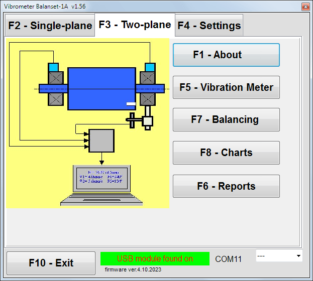
Initial window
پروگرام "Balanset-1A" کو چلاتے وقت ابتدائی ونڈو ظاہر ہوتی ہے، جو کہ تصویر 7.1 میں دکھائی گئی ہے۔.

تصویر 7.1۔ "Balanset-1A" کی ابتدائی ونڈو"
ابتدائی ونڈو میں 9 بٹن ہیں جن پر کلک کرنے پر فنکشنز کے نام معلوم ہوتے ہیں۔
F1-«About»
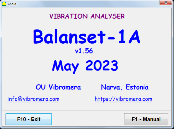
تصویر 7.2۔ F1 - "کے بارے میں" ونڈو
F2-«Single plane», F3-«Two plane»
دبانا ""F2- سنگل ہوائی جہاز""(یا F2 کمپیوٹر کی بورڈ پر فنکشن کلید) چینل پر پیمائش کے کمپن کا انتخاب کرتا ہے۔ X1.
After clicking this button, the computer display diagram shown in Fig. 7.1 illustrating a process of measuring the vibration only on the first measuring channel (or the balancing process in a single plane).
دبانے سے ""F3-دو ہوائی جہاز""(یا F3 function key on the computer keyboard) selects the mode of vibration measurements on two channels X1 and X2 simultaneously. (Fig. 7.3.)
تصویر 7.3۔ "Balanset-1A" کی ابتدائی ونڈو۔ دو ہوائی جہاز کا توازن۔.
F4 - "ترتیبات"
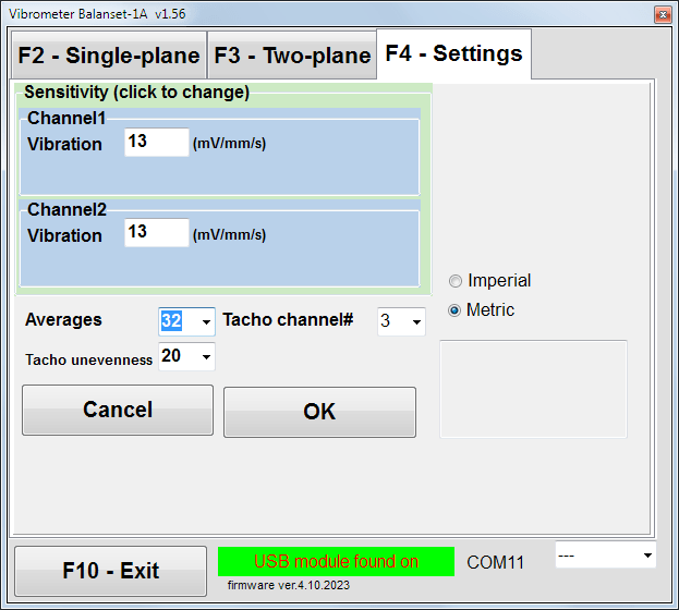
تصویر 7.4۔ "ترتیبات" ونڈو
In this window you can change some Balanset-1A settings.
- Sensitivity. The nominal value is 13 mV / mm/s.
Changing the sensitivity coefficients of sensors is required only when replacing sensors!
Attention!
جب آپ حساسیت کے گتانک میں داخل ہوتے ہیں تو اس کا جزوی حصہ اعشاریہ کے ساتھ عددی حصے سے الگ ہوجاتا ہے (نشان ",")۔.
- Averaging - اوسط کی تعداد (روٹر کی گردشوں کی تعداد جس پر اعداد و شمار کو زیادہ درستگی تک اوسط کیا جاتا ہے)
- Tacho channel# - channel# ٹیچو منسلک ہے۔ پہلے سے طے شدہ - تیسرا چینل۔.
- Unevenness - ملحقہ ٹیچو دالوں کے درمیان دورانیہ کا فرق، جو اوپر انتباہ دیتا ہے ""Failure of the tachometer"
- Imperial/Metric - یونٹس کا نظام منتخب کریں۔.
Com port number is assigned automatically.
F5 - "وائبریشن میٹر"
Pressing this button (or a function key of F5 کمپیوٹر کی بورڈ پر) بٹنوں کی حالت کے لحاظ سے ورچوئل وائبریشن میٹر کے ایک یا دو پیمائشی چینلز پر کمپن کی پیمائش کے موڈ کو چالو کرتا ہے ""F2-ایک ہوائی جہاز""F3-دو ہوائی جہاز"۔.
F6 - "رپورٹس"
Pressing this button (or F6 function key on the computer keyboard) switches on the balancing Archive, from which you can print the report with the results of balancing for a specific mechanism (rotor).
F7 – «Balancing»
اس بٹن کو دبانے سے (یا آپ کے کی بورڈ پر فنکشن کلید F7) ایک یا دو اصلاحی طیاروں میں بیلنسنگ موڈ کو چالو کرتا ہے اس پر منحصر ہے کہ بٹنوں کو دبانے سے پیمائش کا کون سا موڈ منتخب کیا گیا ہے۔"F2-ایک ہوائی جہاز""F3-دو ہوائی جہاز"۔.
F8 – «Charts»
Pressing this button (or F8 کمپیوٹر کے کی بورڈ پر فنکشن کلید) گرافک وائبریشن میٹر کو قابل بناتا ہے، جس کا نفاذ ڈسپلے پر بیک وقت اپنے وقت کے فنکشن کے کمپن گرافکس کے طول و عرض اور فیز کی ڈیجیٹل اقدار کے ساتھ ظاہر ہوتا ہے۔.
F10 - "باہر نکلیں"
Pressing this button (or F10 کمپیوٹر کے کی بورڈ پر فنکشن کلید) پروگرام "Balanset-1A" کو مکمل کرتی ہے۔.
7.2 "وائبریشن میٹر""
میں کام کرنے سے پہلے ""Vibration meter"" موڈ، مشین پر وائبریشن سینسرز انسٹال کریں اور انہیں بالترتیب USB انٹرفیس یونٹ کے کنیکٹر X1 اور X2 سے جوڑیں۔ Tacho سینسر کو USB انٹرفیس یونٹ کے ان پٹ X3 سے منسلک ہونا چاہیے۔.

Fig. 7.5 USB interface unit
ٹاچو کام کرنے کے لیے روٹر کی سطح پر عکاس ٹیپ رکھیں۔

تصویر 7.6۔ عکاس ٹیپ.
Recommendations for the installation and configuration of sensors are given in Annex 1.
وائبریشن میٹر موڈ میں پیمائش شروع کرنے کے لیے بٹن پر کلک کریں ""F5 – Vibration Meter"پروگرام کی ابتدائی ونڈو میں (دیکھیں تصویر 7.1)۔.
Vibration Meter window appears (see. Fig.7.7)

Fig. 7.7. Vibration meter mode. Wave and Spectrum.
کمپن کی پیمائش شروع کرنے کے لیے بٹن پر کلک کریں ""F9 - چلائیں۔"" (یا فنکشن کی کو دبائیں۔ F9 on the keyboard).
If ٹرگر موڈ آٹو چیک کیا جاتا ہے - کمپن کی پیمائش کے نتائج وقتا فوقتا اسکرین پر دکھائے جائیں گے۔.
پہلے اور دوسرے چینلز پر کمپن کی بیک وقت پیمائش کی صورت میں، الفاظ کے نیچے موجود ونڈوز"Plane 1""اور""Plane 2"" بھر جائے گا.
"وائبریشن" موڈ میں کمپن کی پیمائش بھی منقطع فیز اینگل سینسر کے ساتھ کی جا سکتی ہے۔ پروگرام کی ابتدائی ونڈو میں کل RMS وائبریشن کی قدر (V1s, V2s) will only be displayed.
وائبریشن میٹر موڈ میں اگلی سیٹنگز ہیں۔
- RMS Low, Hz - مجموعی کمپن کے RMS کا حساب لگانے کے لیے سب سے کم تعدد
- بینڈوڈتھ - چارٹ میں کمپن فریکوئنسی بینڈوتھ
- Averages - زیادہ پیمائش کی درستگی کے لیے اوسط کی تعداد
"وائبریشن میٹر" موڈ میں کام مکمل کرنے کے لیے بٹن پر کلک کریں۔"F10 – Exit""اور ابتدائی ونڈو پر واپس جائیں۔.

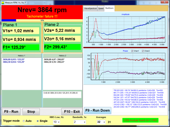
Fig. 7.8. Vibration meter mode. Rotation speed Unevenness, 1x vibration wave form.
Fig. 7.9. Vibration meter mode. Rundown (beta version, no warranty!).
7.3 توازن کا طریقہ کار
Balancing is performed for mechanisms in good technical condition and correctly mounted. Otherwise, before the balancing the mechanism must be repaired, installed in proper bearings and fixed. Rotor should be cleaned of contaminants that can hinder from balancing procedure.
Before balancing measure vibration in Vibration meter mode (F5 button) to be sure that mainly vibration is 1x vibration.
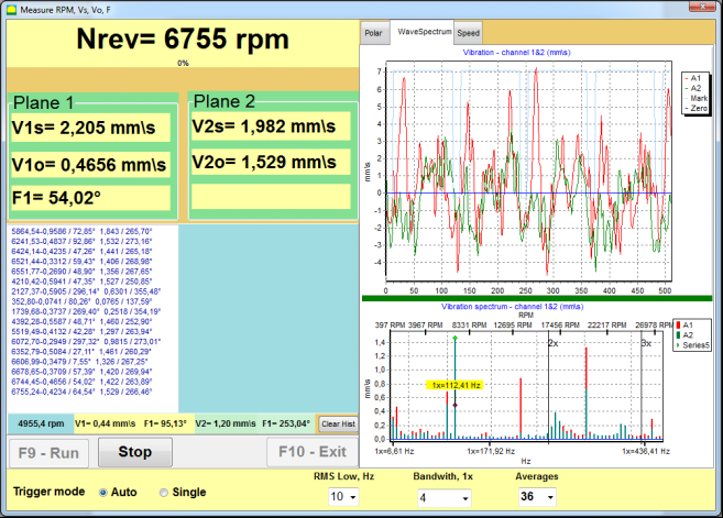
Fig. 7.10. Vibration meter mode. Checking overall (V1s,V2s) and 1x (V1o,V2o) vibration.
اگر مجموعی وائبریشن V1s (V2s) کی قدر گردشی فریکوئنسی (1x کمپن) V1o (V2o) پر کمپن کی شدت کے تقریباً برابر ہے، تو یہ فرض کیا جا سکتا ہے کہ کمپن میکانزم میں بنیادی شراکت روٹر کے عدم توازن سے آتی ہے۔ اگر مجموعی وائبریشن V1s (V2s) کی ویلیو 1x وائبریشن کمپوننٹ V1o (V2o) سے بہت زیادہ ہے، تو یہ تجویز کی جاتی ہے کہ میکانزم کی حالت کو چیک کیا جائے - بیرنگ کی حالت، اس کی بنیاد پر نصب، اس بات کو یقینی بنائیں کہ گردش کے دوران مقررہ حصوں اور روٹر کے درمیان کوئی رابطہ نہ ہو۔
آپ کو وائبریشن میٹر موڈ میں ماپی گئی قدروں کے استحکام پر بھی توجہ دینی چاہیے – پیمائش کے عمل میں کمپن کا طول و عرض اور مرحلہ 10-15% سے زیادہ مختلف نہیں ہونا چاہیے۔ دوسری صورت میں، یہ فرض کیا جا سکتا ہے کہ میکانزم قریبی سے گونج والے علاقے میں کام کر رہا ہے. اس صورت میں، روٹر کی گردش کی رفتار کو تبدیل کریں، اور اگر یہ ممکن نہیں ہے - فاؤنڈیشن پر مشین کی تنصیب کی شرائط کو تبدیل کریں (مثال کے طور پر، اسے موسم بہار کی حمایت پر عارضی طور پر نصب کریں).
روٹر توازن کے لئے اثر گتانک کا طریقہ بیلنسنگ (3-رن کا طریقہ) استعمال کیا جانا چاہئے۔
Trial runs are done to determine the effect of trial mass on vibration change, mass and place (angle) of installation of correction weights.
First determine the original vibration of a mechanism (first start without weight), and then set the trial weight to the first plane and made the second start. Then, remove the trial weight from the first plane, set in a second plane and made the second start.
The program then calculates and indicates on the screen the weight and location (angle) of installation of correction weights.
When balancing in a single plane (static), the second start is not required.
Trial weight is set to an arbitrary location on the rotor where it is convenient, and then the actual radius is entered in the setup program.
(Position Radius is used only for calculating the unbalance amount in grams * mm)
Important!
- Measurements should be carried out with the constant speed of rotation of the mechanism!
- Correction weights must be installed on the same radius as the trial weights!
آزمائشی وزن کا بڑے پیمانے پر انتخاب کیا جاتا ہے تاکہ اس کی تنصیب کے مرحلے (> 20-30°) اور (20-30%) کے بعد کمپن کا طول و عرض نمایاں طور پر تبدیل ہوجائے۔ اگر تبدیلیاں بہت چھوٹی ہیں، تو بعد کے حسابات میں غلطی بہت بڑھ جاتی ہے۔ آزمائشی ماس کو اسی جگہ (ایک ہی زاویہ) پر فیز مارک کے طور پر آسانی سے سیٹ کریں۔
آزمائشی وزن کے بڑے پیمانے پر حساب کتاب کا فارمولا
Mt = Mr × Ksupport × Kvibration / (Rt × (N/100)²)
کہاں:
- ماؤنٹ - آزمائشی وزن کے بڑے پیمانے پر، جی
- مسٹر - روٹر ماس، جی
- کے سپورٹ - سپورٹ سختی گتانک (1-5)
- Kvibration - وائبریشن لیول گتانک (0.5-2.5)
- Rt - آزمائشی وزن کی تنصیب کا رداس، سینٹی میٹر
- ن - روٹر کی رفتار، rpm
سپورٹ سختی گتانک (Ksupport):
- 1.0 - بہت نرم سپورٹ (ربڑ ڈیمپرز)
- 2.0-3.0 - درمیانی سختی (معیاری بیرنگ)
- 4.0-5.0 - سخت سپورٹ (بڑے پیمانے پر فاؤنڈیشن)
وائبریشن لیول گتانک (Kvibration):
- 0.5 - کم کمپن (5 ملی میٹر فی سیکنڈ تک)
- 1.0 - نارمل کمپن (5-10 ملی میٹر/سیکنڈ)
- 1.5 - بلند کمپن (10-20 ملی میٹر/سیکنڈ)
- 2.0 - ہائی وائبریشن (20-40 ملی میٹر/سیکنڈ)
- 2.5 - بہت زیادہ کمپن (>40 ملی میٹر/سیکنڈ)
🔗 ہمارا آن لائن کیلکولیٹر استعمال کریں:
آزمائشی وزن کیلکولیٹر →⚠️ اہم!
After each test run trial mass are removed! Correction weights set at an angle calculated from the place of trial weight installation in the direction of rotation of the rotor!
زاویہ حساب کی وضاحت:
اصلاح وزن کی تنصیب زاویہ ہے ۔ ہمیشہ روٹر گردش کی سمت میں آزمائشی وزن کی تنصیب کے نقطہ سے شمار کیا جاتا ہے.
- زیرو پوائنٹ (0°): صحیح جگہ جہاں آپ نے آزمائشی وزن نصب کیا وہ آپ کا حوالہ نقطہ (0 ڈگری) بن جاتا ہے۔.
- سمت: زاویہ کو اسی سمت میں پیمائش کریں جس میں روٹر گھومتا ہے۔.
مثال: اگر روٹر گھڑی کی سمت گھومتا ہے، تو آزمائشی وزن کی پوزیشن سے زاویہ گھڑی کی سمت کی پیمائش کریں۔. - تشریح: اگر پروگرام کا زاویہ دکھاتا ہے۔ 120°, ، آپ کو درست وزن کو انسٹال کرنا ہوگا۔ 120 ڈگری آگے گردش کی سمت میں آزمائشی وزن کی پوزیشن کا۔.
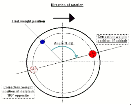
Fig. 7.11. Correction weight mounting.
تجویز کردہ!
متحرک توازن کو انجام دینے سے پہلے، یہ یقینی بنانے کی سفارش کی جاتی ہے کہ جامد عدم توازن بہت زیادہ نہ ہو۔ افقی محور والے روٹرز کے لیے، روٹر کو دستی طور پر موجودہ پوزیشن سے 90 ڈگری کے زاویے سے گھمایا جا سکتا ہے۔ اگر روٹر مستحکم طور پر غیر متوازن ہے، تو اسے توازن کی پوزیشن پر گھمایا جائے گا۔ ایک بار جب روٹر توازن کی پوزیشن سنبھال لیتا ہے، تو یہ ضروری ہے کہ توازن وزن کو روٹر کی لمبائی کے درمیانی حصے میں سب سے اوپر پوائنٹ پر نصب کیا جائے۔ وزن کا انتخاب اس طرح کیا جائے کہ روٹر کسی بھی پوزیشن میں حرکت نہ کر رہا ہو۔
اس طرح کا پری بیلنسنگ ایک مضبوط غیر متوازن روٹر کے پہلے آغاز پر کمپن کی مقدار کو کم کر دے گا۔
سینسر کی تنصیب اور بڑھتے ہوئے
ویibration sensor must be installed on the machine in the selected measuring point and connected to the input X1 of the USB interface unit.
دو بڑھتے ہوئے کنفیگریشنز ہیں:
- میگنےٹ
- Threaded studs M4
Optical tacho sensor should be connected to the input X3 of the USB interface unit. Furthermore, for use of this sensor a special reflecting mark should be applied on surface of a rotor.
📏 آپٹیکل سینسر کی تنصیب کے تقاضے
- ✓روٹر کی سطح کا فاصلہ: 50-500 ملی میٹر (سینسر ماڈل پر منحصر ہے)
- ✓عکاس ٹیپ کی چوڑائی: کم از کم 1-1.5 سینٹی میٹر (رفتار اور رداس پر منحصر ہے)
- ✓واقفیت: روٹر کی سطح پر کھڑا
- ✓چڑھنا: مستحکم پوزیشننگ کے لیے مقناطیسی اسٹینڈ یا کلیمپ کا استعمال کریں۔
- ✓براہ راست سورج کی روشنی سے بچیں یا سینسر/ٹیپ پر روشن مصنوعی روشنی
💡 ٹیپ کی چوڑائی کا حساب کتاب: بہترین کارکردگی کے لیے، اس کا استعمال کرتے ہوئے ٹیپ کی چوڑائی کا حساب لگائیں:
L ≥ (N × R)/30000 ≥ 1.0-1.5 سینٹی میٹر
کہاں: L - ٹیپ کی چوڑائی (سینٹی میٹر)، N - روٹر کی رفتار (rpm)، R - ٹیپ کا رداس (سینٹی میٹر)
Detailed requirements on site selection of the sensors and their attachment to the object when balancing are set out in Annex 1.
7.4 سنگل ہوائی جہاز کا توازن
تصویر 7.12۔ "سنگل ہوائی جہاز کا توازن"
آرکائیو کو متوازن کرنا
پروگرام پر کام شروع کرنے کے لیے ""Single-Plane balancing""موڈ، پر کلک کریں""F2-Single-plane"بٹن (یا کمپیوٹر کی بورڈ پر F2 کی دبائیں)۔.
پھر کلک کریں ""F7 – Balancing""بٹن، جس کے بعد Single Plane balancing archive window will appear, in which the balancing data will be saved (see Fig. 7.13).

Fig. 7.13 The window for selecting the balancing archive in single plane.
In this window, you need to enter data on the name of the rotor (Rotor name), place of rotor installation (Place), tolerances for vibration and residual imbalance (Tolerance), date of measurement. This data is stored in a database. Also, a folder Arc### is created in, where ### is the number of the archive in which the charts, a report file, etc. will be saved. After the balancing is completed, a report file will be generated that can be edited and printed in the built-in editor.
ضروری ڈیٹا داخل کرنے کے بعد، آپ کو کلک کرنے کی ضرورت ہے ""F10-OK""بٹن، جس کے بعد""Single-Plane balancing"ونڈو کھل جائے گی (تصویر 7.13 دیکھیں)
Balancing settings (1-plane)

Fig. 7.14. Single plane. Balancing settings
اس ونڈو کے بائیں جانب کمپن کی پیمائش کا ڈیٹا اور پیمائش کنٹرول بٹن دکھاتا ہے ""Run # 0", "Run # 1", "RunTrim".
اس ونڈو کے دائیں جانب تین ٹیبز ہیں:
- Balancing settings
- Charts
- Result
""Balancing settings"" ٹیب کو توازن کی ترتیبات میں داخل کرنے کے لیے استعمال کیا جاتا ہے:
- ""اثر اندازی"" -
- "New Rotor"" - نئے روٹر کے توازن کا انتخاب، جس کے لیے کوئی ذخیرہ شدہ توازن گتانک نہیں ہیں اور درستی وزن کے بڑے پیمانے اور تنصیب کے زاویے کا تعین کرنے کے لیے دو رنز درکار ہیں۔.
- "Saved coeff."" - روٹر ری بیلنسنگ کا انتخاب، جس کے لیے محفوظ شدہ توازن کے گتانک موجود ہیں اور اصلاحی وزن کے وزن اور تنصیب کے زاویے کا تعین کرنے کے لیے صرف ایک رن کی ضرورت ہے۔.
- ""آزمائشی وزن ماس"" -
- "Percent"" - اصلاحی وزن کو آزمائشی وزن کے فیصد کے طور پر شمار کیا جاتا ہے۔.
- "Gram"" - آزمائشی وزن کا معلوم ماس درج کیا جاتا ہے اور اصلاحی وزن کے بڑے پیمانے پر شمار کیا جاتا ہے۔ grams or in oz for Imperial system.
⚠️ توجہ! اگر استعمال کرنا ضروری ہو تو ""Saved coeff.""ابتدائی توازن کے دوران مزید کام کے لیے موڈ، ٹرائل ویٹ ماس کو گرام یا اوز میں داخل کیا جانا چاہیے، % میں نہیں۔ ترازو ڈیلیوری پیکیج میں شامل ہیں۔.
- ""وزن منسلک کرنے کا طریقہ""
- "Free position"" - روٹر کے فریم پر صوابدیدی کونیی پوزیشنوں میں وزن نصب کیے جا سکتے ہیں۔.
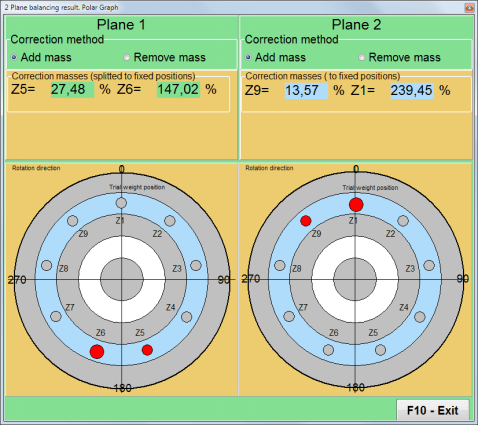
- "Fixed position"" - روٹر پر وزن کو مقررہ کونیی پوزیشنوں میں نصب کیا جا سکتا ہے، مثال کے طور پر، بلیڈ یا سوراخوں پر (مثال کے طور پر 12 سوراخ - 30 ڈگری)، وغیرہ۔ مقررہ پوزیشنوں کی تعداد کو مناسب فیلڈ میں داخل کرنا ضروری ہے۔ توازن کے بعد، پروگرام خود بخود وزن کو دو حصوں میں تقسیم کر دے گا اور ان پوزیشنوں کی تعداد کی نشاندہی کرے گا جن پر ماس قائم کرنا ضروری ہے۔.
- "Circular groove""- وہیل بیلنسنگ کو پیسنے کے لیے استعمال کیا جاتا ہے اس معاملے میں عدم توازن کو ختم کرنے کے لیے 3 کاؤنٹر ویٹ استعمال کیے جاتے ہیں۔
Fig. 7.17 Grinding wheel balancing with 3 counterweights
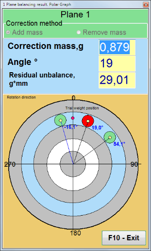
Fig. 7.18 Grinding wheel balancing. Polar graph.

Fig. 7.15. Result tab. Fixed position of correction weight mounting.
Z1 اور Z2 - نصب اصلاحی وزن کی پوزیشنیں، گردش کی سمت کے مطابق Z1 پوزیشن سے شمار کی جاتی ہیں۔ Z1 وہ پوزیشن ہے جہاں آزمائشی وزن نصب کیا گیا تھا۔
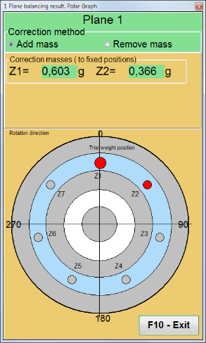
Fig. 7.16 Fixed positions. Polar diagram.
- "Mass mount radius, mm"" - "Plane1" - 1 جہاز میں آزمائشی وزن کا رداس۔ توازن کے بعد بقایا عدم توازن کی رواداری کے ساتھ تعمیل کا تعین کرنے کے لیے ابتدائی اور بقایا عدم توازن کی شدت کا حساب لگانا ضروری ہے۔.
- "Leave trial weight in Plane1."عام طور پر آزمائشی وزن کو توازن کے عمل کے دوران ہٹا دیا جاتا ہے۔ لیکن بعض صورتوں میں اسے ہٹانا ناممکن ہوتا ہے، پھر آپ کو حساب میں آزمائشی وزن کے بڑے پیمانے پر حساب کرنے کے لیے اس میں ایک چیک مارک سیٹ کرنا ہوگا۔.
- "Manual data input"" - ونڈو کے بائیں جانب مناسب فیلڈز میں وائبریشن ویلیو اور فیز کو دستی طور پر داخل کرنے اور تصحیح وزن کے بڑے پیمانے اور تنصیب کے زاویے کا حساب لگانے کے لیے استعمال کیا جاتا ہے جب ""Results""ٹیب
- بٹن""Restore session data"توازن کے دوران، پیمائش شدہ ڈیٹا کو session1.ini فائل میں محفوظ کیا جاتا ہے۔ اگر کمپیوٹر کے منجمد ہونے یا دیگر وجوہات کی وجہ سے پیمائش کے عمل میں خلل پڑا تھا، تو اس بٹن پر کلک کر کے آپ پیمائش کے ڈیٹا کو بحال کر سکتے ہیں اور رکاوٹ کے لمحے سے توازن برقرار رکھ سکتے ہیں۔.
- Mandrel eccentricity elimination (Index balancing) Balancing with additional start to eliminate the influence of the eccentricity of the mandrel (balancing arbor). Mount the rotor alternately at 0° and 180° relative to the. Measure the unbalances in both positions.
- Balancing tolerance Entering or calculating residual imbalance tolerances in g x mm (G-classes)
- Use Polar Graph Use polar graph to display balancing results
1-plane Balancing. New rotor
جیسا کہ اوپر لکھا گیا ہے، ""New Rotor"توازن کے لیے دو ٹیسٹ رنز اور بیلنسنگ مشین کے کم از کم ایک ٹرم رن کی ضرورت ہوتی ہے۔.
Run#0 (Initial run)
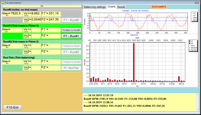
بیلنسنگ روٹر پر سینسرز کو انسٹال کرنے اور سیٹنگ کے پیرامیٹرز میں داخل ہونے کے بعد، روٹر کی گردش کو آن کرنا ضروری ہے اور جب یہ کام کرنے کی رفتار تک پہنچ جائے تو "دبائیں۔"Run#0"پیمائش شروع کرنے کے لیے بٹن۔"Charts"" ٹیب دائیں پینل میں کھلے گا، جہاں وائبریشن کی لہر کی شکل اور اسپیکٹرم دکھایا جائے گا۔ ٹیب کے نیچے والے حصے میں، ایک ہسٹری فائل رکھی گئی ہے، جس میں وقت کے حوالے سے شروع ہونے والے تمام نتائج محفوظ کیے جاتے ہیں۔ ڈسک پر، یہ فائل memo.txt کے نام سے آرکائیو فولڈر میں محفوظ کی جاتی ہے۔
Attention!
Before starting the measurement, it is necessary to turn on the rotation of the rotor of the balancing machine (Run#0) and make sure that the rotor speed is stable.
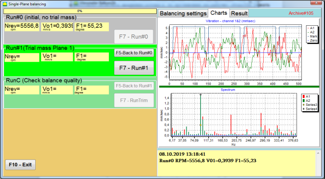
Fig. 7.19. Balancing in one plane. Initial run (Run#0). Charts Tab
After measurement process finished, in the Run#0 بائیں پینل کے حصے میں پیمائش کے نتائج ظاہر ہوتے ہیں - روٹر کی رفتار (RPM)، RMS (Vo1) اور 1x کمپن کا مرحلہ (F1)۔.
""F5-Back to Run#0"" بٹن (یا F5 فنکشن کلید) Run#0 سیکشن پر واپس جانے کے لیے استعمال کیا جاتا ہے اور اگر ضروری ہو تو، کمپن پیرامیٹرز کو دہرانے کے لیے۔.
Run#1 (Trial mass Plane 1)
سیکشن میں کمپن پیرامیٹرز کی پیمائش شروع کرنے سے پہلے ""Run#1 (Trial mass Plane 1), ، ایک آزمائشی وزن کے مطابق نصب کیا جانا چاہئے ""Trial weight mass""میدان۔.
The goal of installing a trial weight is to evaluate how the vibration of the rotor changes when a known weight is installed at a known place (angle). Trial weight must changes the vibration amplitude by either 30% lower or higher of initial amplitude or change phase by 30 degrees or more of initial phase.
اگر استعمال کرنا ضروری ہو تو ""Saved coeff."مزید کام کے لیے توازن کرتے ہوئے، آزمائشی وزن کی تنصیب کی جگہ (زاویہ) عکاس نشان کی جگہ (زاویہ) جیسا ہی ہونا چاہیے۔.
بیلنسنگ مشین کے روٹر کی گردش کو دوبارہ آن کریں اور یقینی بنائیں کہ اس کی گردش کی فریکوئنسی مستحکم ہے۔ پھر کلک کریں ""F7-Run#1"بٹن (یا کمپیوٹر کی بورڈ پر F7 بٹن دبائیں)۔.
کی متعلقہ کھڑکیوں میں پیمائش کے بعد ""Run#1 (Trial mass Plane 1)"" سیکشن، روٹر کی رفتار (RPM) کی پیمائش کے نتائج کے ساتھ ساتھ RMS جزو (Vо1) اور 1x کمپن کے فیز (F1) کی قدر۔.
ایک ہی وقت میں، ""Result"" ٹیب ونڈو کے دائیں جانب کھلتا ہے۔.
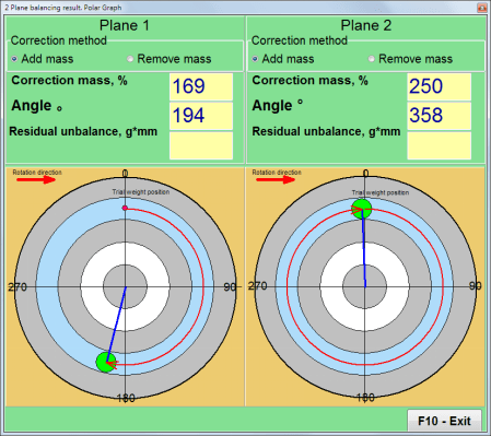
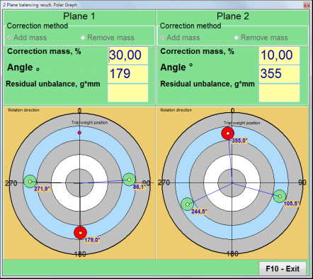
This tab displays the results of calculating the mass and angle of corrective weight, which must be installed on the rotor to compensate imbalance.
مزید برآں، پولر کوآرڈینیٹ سسٹم کو استعمال کرنے کی صورت میں، ڈسپلے ماس ویلیو (M1) اور اصلاحی وزن کا انسٹالیشن اینگل (f1) دکھاتا ہے۔
کی صورت میں ""Fixed positions"" پوزیشنز کی تعداد (Zi، Zj) اور آزمائشی وزن میں تقسیم شدہ ماس دکھایا جائے گا۔.
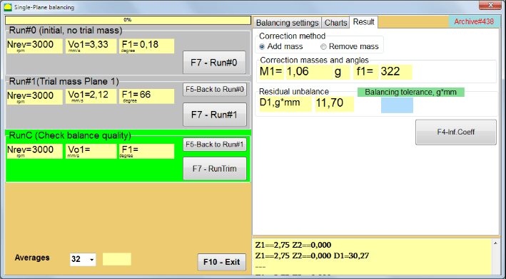
Fig. 7.20. Balancing in one plane. Run#1 and balancing result.
If Polar graph is checked polar diagram will be shown.
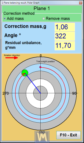
Fig. 7.21. The result of balancing. Polar graph.
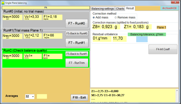
Fig. 7.22. The result of balancing. Weight splitted (fixed positions)
اس کے علاوہ اگر ""Polar graph""چیک کیا گیا تھا، پولر گراف دکھایا جائے گا.
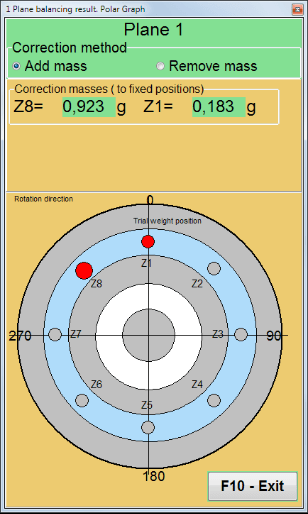
Fig. 7.23. Weight splitted on fixed positions. Polar graph
⚠️ توجہ!
- دوسرے رن پر پیمائش کے عمل کو مکمل کرنے کے بعد (""Run#1 (Trial mass Plane 1)"بیلنسنگ مشین کی، گردش کو روکنا اور نصب شدہ آزمائشی وزن کو ہٹانا ضروری ہے۔ پھر رزلٹ ٹیب ڈیٹا کے مطابق روٹر پر اصلاحی وزن کو انسٹال کریں (یا ہٹا دیں)۔.
اگر آزمائشی وزن کو ہٹایا نہیں گیا تھا، تو آپ کو ""Balancing settings""ٹیب اور چیک باکس کو آن کریں""Leave trial weight in Plane1"پھر واپس سوئچ کریں ""Result"" ٹیب۔ اصلاحی وزن کا وزن اور تنصیب کا زاویہ خود بخود دوبارہ شمار کیا جاتا ہے۔.
- اصلاحی وزن کی کونیی پوزیشن آزمائشی وزن کی تنصیب کی جگہ سے انجام دی جاتی ہے۔ زاویہ کے حوالہ کی سمت روٹر کی گردش کی سمت کے مطابق ہے۔
- کی صورت میں ""Fixed position""-1st position (Z1), coincides with the place of installation of the trial weight. The counting direction of the position number is in the direction of rotation of the rotor.
- پہلے سے طے شدہ طور پر اصلاحی وزن روٹر میں شامل کیا جائے گا۔ اس کی نشاندہی اس لیبل سے ہوتی ہے جو ""Add"" فیلڈ۔ اگر وزن ہٹا رہے ہیں (مثال کے طور پر، ڈرلنگ کے ذریعے)، تو آپ کو ""Delete"" فیلڈ، جس کے بعد درستی کے وزن کی کونیی پوزیشن خود بخود 180º تک بدل جائے گی۔.
آپریٹنگ ونڈو میں بیلنسنگ روٹر پر کریکشن وزن کو انسٹال کرنے کے بعد، یہ ضروری ہے کہ ایک RunC (ٹرم) کریں اور انجام دیے گئے بیلنسنگ کی تاثیر کا جائزہ لیں۔
RunC (Check balance quality)
⚠️ توجہ! Before starting the measurement on the RunC, it is necessary to turn on the rotation of the rotor of the machine and make sure that it has entered the operating mode (stable rotation frequency).
کمپن کی پیمائش کرنے کے لیے ""RunC (Check balance quality)""سیکشن، پر کلک کریں""F7 – RunTrim"بٹن (یا کی بورڈ پر F7 بٹن دبائیں)۔.
پیمائش کے عمل کی کامیاب تکمیل پر، ""RunC (Check balance quality)"" بائیں پینل میں سیکشن، روٹر کی رفتار (RPM) کی پیمائش کے نتائج ظاہر ہوتے ہیں، ساتھ ہی RMS جزو (Vo1) اور 1x وائبریشن کے فیز (F1) کی قدر۔.
میں ""Result"" ٹیب، اضافی اصلاحی وزن کے بڑے پیمانے پر اور تنصیب کے زاویہ کا حساب لگانے کے نتائج ظاہر ہوتے ہیں۔.
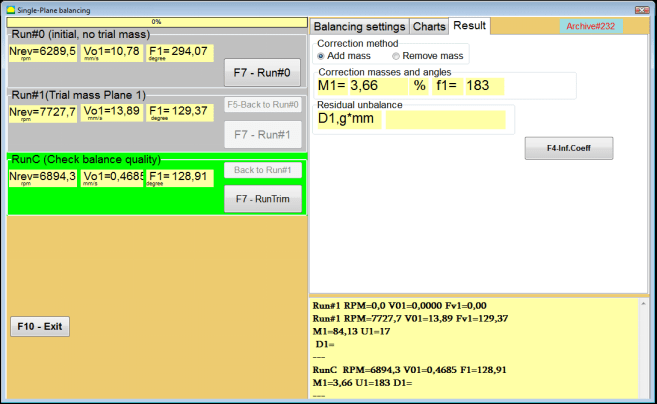
Fig. 7.24. Balancing in one plane. Performing a RunTrim. Result Tab
This weight can be added to the correction weight that is already mounted on the rotor to compensate for the residual imbalance. In addition, the residual rotor unbalance achieved after balancing is displayed in the lower part of this window.
In the case when the amount of residual vibration and / or residual unbalance of the balanced rotor meets the tolerance requirements established in the technical documentation, the balancing process can be completed.
Otherwise, the balancing process may continue. This allows the method of successive approximations to correct possible errors that may occur during the installation (removal) of the corrective weight on a balanced rotor.
بیلنسنگ روٹر پر بیلنسنگ کے عمل کو جاری رکھتے ہوئے، اضافی اصلاحی ماس کو انسٹال کرنا (ہٹانا) ضروری ہے، جس کے پیرامیٹرز سیکشن میں بتائے گئے ہیں۔"Correction masses and angles".
Influence coefficients (1-plane)
""F4-Inf.Coeff""میں بٹن""Result"" ٹیب کا استعمال روٹر بیلنسنگ کے گتانکوں کو دیکھنے اور ذخیرہ کرنے کے لیے کیا جاتا ہے جو کیلیبریشن رنز کے نتائج سے حساب کیا جاتا ہے۔.
جب اسے دبایا جاتا ہے، ""Influence coefficients (single plane)"کمپیوٹر ڈسپلے پر ونڈو نمودار ہوتی ہے، جس میں کیلیبریشن (ٹیسٹ) رنز کے نتائج سے حساب کیے گئے بیلنسنگ گتانک دکھائے جاتے ہیں۔ اگر اس مشین کے بعد کے توازن کے دوران یہ سمجھا جاتا ہے کہ ""Saved coeff."" موڈ، ان گتانکوں کو کمپیوٹر میموری میں محفوظ کیا جانا چاہیے۔.
ایسا کرنے کے لیے، کلک کریں ""F9 - محفوظ کریں۔""بٹن اور دوسرے صفحے پر جائیں""کوف کو متاثر کریں۔ محفوظ شدہ دستاویزات اکیلا طیارہ۔"

Fig. 7.25. Balancing coefficients in the 1st plane
پھر آپ کو اس مشین کا نام درج کرنے کی ضرورت ہے ""Rotor""کالم اور کلک کریں""F2-Save"کمپیوٹر پر مخصوص ڈیٹا کو محفوظ کرنے کے لیے بٹن۔.
پھر آپ "دب کر پچھلی ونڈو پر واپس جا سکتے ہیں۔"F10-Exit"بٹن (یا کمپیوٹر کی بورڈ پر F10 فنکشن کلید)۔.
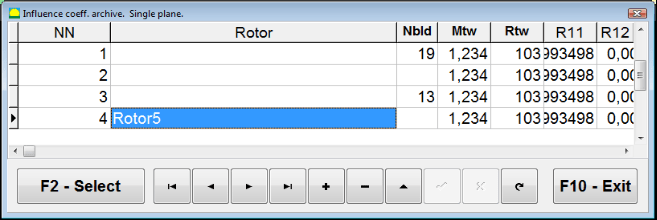
تصویر 7.26۔ "انفلوئنس کوف۔ آرکائیو۔ سنگل ہوائی جہاز۔""
Balancing report
تمام ڈیٹا کو بیلنس کرنے کے بعد محفوظ کیا گیا اور بیلنسنگ رپورٹ بنائی گئی۔ آپ بلٹ ان ایڈیٹر میں رپورٹ دیکھ اور اس میں ترمیم کر سکتے ہیں۔ کھڑکی میں ""ایک ہوائی جہاز میں محفوظ شدہ دستاویزات کا توازن"" (تصویر 7.9) بٹن دبائیں ""F9 -Report"بیلنسنگ رپورٹ ایڈیٹر تک رسائی حاصل کرنے کے لیے۔.
تصویر 7.27۔ توازن رپورٹ۔
محفوظ شدہ کوف۔ 1 طیارے میں محفوظ کردہ اثر و رسوخ کے ساتھ توازن کا طریقہ کار
پیمائش کا نظام ترتیب دینا (ابتدائی ڈیٹا کا ان پٹ)
Saved coeff. balancing can be performed on a machine for which balancing coefficients have already been determined and entered into the computer memory.
⚠️ توجہ! When balancing with saved coefficients, the vibration sensor and the phase angle sensor must be installed in the same way as during the initial balancing.
Input of the initial data for Saved coeff. balancing (جیسا کہ پرائمری کے معاملے میں)"New rotor"") توازن)" میں شروع ہوتا ہے"Single plane balancing. Balancing settings.".
اس صورت میں، ""Influence coefficients""سیکشن، منتخب کریں""Saved coeff""آئٹم۔ اس صورت میں، کا دوسرا صفحہ""Influence coeff. archive. Single plane."، جو محفوظ شدہ بیلنسنگ گتانکوں کا ایک آرکائیو ذخیرہ کرتا ہے۔.
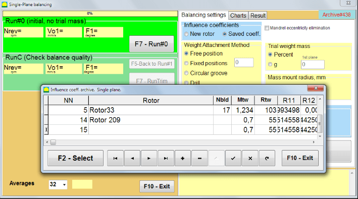
Fig. 7.28. Balancing with saved influence coefficients in 1 plane
"►" یا "◄" کنٹرول بٹنوں کا استعمال کرتے ہوئے اس آرکائیو کے ٹیبل میں آگے بڑھتے ہوئے، آپ ہماری دلچسپی کی مشین کے توازن گتانک کے ساتھ مطلوبہ ریکارڈ منتخب کر سکتے ہیں۔ پھر، موجودہ پیمائش میں اس ڈیٹا کو استعمال کرنے کے لیے، دبائیں ""F2 – Select""بٹن.
اس کے بعد، دیگر تمام ونڈوز کے مواد ""Single plane balancing. Balancing settings."خود بخود بھرے جاتے ہیں۔.
After completing the input of the initial data, you can begin to measure.
محفوظ کردہ اثر و رسوخ کے ساتھ توازن کے دوران پیمائش
Balancing with saved influence coefficients requires only one initial run and at least one test run of the balancing machine.
⚠️ توجہ! Before starting the measurement, it is necessary to turn on the rotation of the rotor and make sure that rotating frequency is stable.
کمپن پیرامیٹرز کی پیمائش کو انجام دینے کے لئے ""Run#0 (Initial, no trial mass)""سیکشن، دبائیں""F7 – Run#0"" (یا کمپیوٹر کی بورڈ پر F7 کی دبائیں)۔.
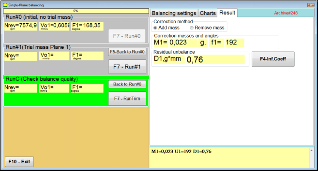
Fig. 7.29. Balancing with saved influence coefficients in one plane. Results after one run.
کے متعلقہ شعبوں میں ""Run#0"" سیکشن، روٹر کی رفتار (RPM) کی پیمائش کے نتائج، RMS جزو (Vо1) کی قدر اور 1x وائبریشن کا مرحلہ (F1) ظاہر ہوتا ہے۔.
ایک ہی وقت میں، ""Result"" ٹیب اصلاحی وزن کے بڑے پیمانے اور زاویہ کا حساب لگانے کے نتائج دکھاتا ہے، جو عدم توازن کی تلافی کے لیے روٹر پر نصب ہونا ضروری ہے۔.
مزید برآں، پولر کوآرڈینیٹ سسٹم استعمال کرنے کی صورت میں، ڈسپلے بڑے پیمانے پر اقدار اور اصلاحی وزن کی تنصیب کے زاویے دکھاتا ہے۔
In the case of splitting of the corrective weight on the fixed positions, the numbers of the positions of the balancing rotor and the mass of weight that need to be installed on them are displayed.
Further, the balancing process is carried out in accordance with the recommendations set out in section 7.4.2. for primary balancing.
Mandrel eccentricity elimination (Index balancing)
If during balancing the rotor is installed in a cylindrical mandrel, then the eccentricity of the mandrel may introduce an additional error. To eliminate this error, the rotor should be deployed in the mandrel 180 degrees and carry out an additional start. This is called index balancing.
To carry out index balancing, a special option is provided in the Balanset-1A program. When checked Mandrel eccentricity elimination an additional RunEcc section appears in the balancing window.

Fig. 7.30. The working window for Index balancing.
After running Run # 1 (Trial mass Plane 1), a window will appear
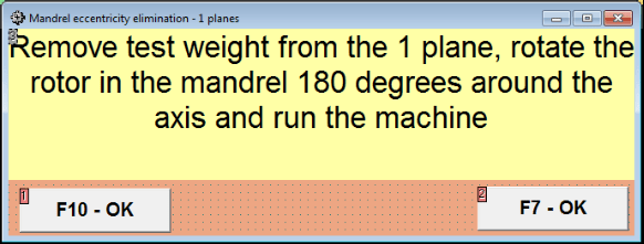
Fig. 7.31 Index balancing attention window.
روٹر کو 180° موڑ کے ساتھ انسٹال کرنے کے بعد، Ecc چلائیں مکمل کرنا ضروری ہے۔ پروگرام خود بخود روٹر کے حقیقی عدم توازن کا حساب لگائے گا بغیر مینڈرل سنکی کو متاثر کیے۔
7.5 دو طیاروں کا توازن
Before starting work in the Two plane balancing mode, it is necessary to install vibration sensors on the machine body at the selected measurement points and connect them to the inputs X1 and X2 of the measuring unit, respectively.
An optical phase angle sensor must be connected to input X3 of the measuring unit. In addition, to use this sensor, a reflective tape must be glued onto the accessible rotor surface of the balancing machine.
Detailed requirements for choosing the installation location of sensors and their mounting at the facility during balancing are set out in Appendix 1.
پروگرام پر کام ""Two plane balancing"" موڈ پروگراموں کی مین ونڈو سے شروع ہوتا ہے۔.
"پر کلک کریں"F3-Two plane"بٹن (یا کمپیوٹر کی بورڈ پر F3 بٹن دبائیں)۔.
مزید، "F7 – توازن" بٹن پر کلک کریں، جس کے بعد کمپیوٹر ڈسپلے پر ایک ورکنگ ونڈو نمودار ہوگی (تصویر 7.13 دیکھیں)، دو طیاروں میں توازن کے دوران ڈیٹا کو محفوظ کرنے کے لیے آرکائیو کا انتخاب۔.
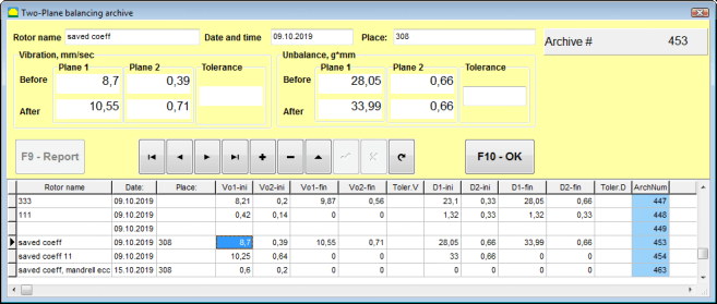
Fig. 7.32 Two plane balancing archive window.
اس ونڈو میں آپ کو متوازن روٹر کا ڈیٹا داخل کرنے کی ضرورت ہے۔ دبانے کے بعد ""F10-OK"" بٹن، ایک بیلنسنگ ونڈو نمودار ہوگی۔.
Balancing settings (2-plane)
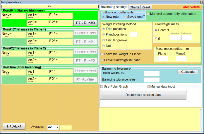
Fig. 7.33. Balancing in two planes window.
کھڑکی کے دائیں جانب ہے ""Balancing settings"توازن سے پہلے ترتیبات میں داخل ہونے کے لیے ٹیب۔.
- Influence coefficients - ایک نئے روٹر کو بیلنس کرنا یا ذخیرہ شدہ اثر و رسوخ کا استعمال کرتے ہوئے توازن (توازن کے گتانک)
- Mandrel eccentricity elimination - مینڈریل کے سنکی پن کے اثر کو ختم کرنے کے لیے اضافی آغاز کے ساتھ توازن قائم کرنا
- Weight Attachment Method - روٹر کے فریم پر من مانی جگہ پر یا ایک مقررہ پوزیشن میں اصلاحی وزن کی تنصیب۔ بڑے پیمانے پر ہٹاتے وقت ڈرلنگ کے لئے حساب۔.
- "Free position"" - روٹر کے فریم پر صوابدیدی کونیی پوزیشنوں میں وزن نصب کیے جا سکتے ہیں۔.
- "Fixed position"" - روٹر پر وزن کو مقررہ کونیی پوزیشنوں میں نصب کیا جا سکتا ہے، مثال کے طور پر، بلیڈ یا سوراخوں پر (مثال کے طور پر 12 سوراخ - 30 ڈگری)، وغیرہ۔ مقررہ پوزیشنوں کی تعداد کو مناسب فیلڈ میں داخل کرنا ضروری ہے۔ توازن کے بعد، پروگرام خود بخود وزن کو دو حصوں میں تقسیم کر دے گا اور ان پوزیشنوں کی تعداد کی نشاندہی کرے گا جن پر ماس قائم کرنا ضروری ہے۔.
- Trial weight mass - آزمائشی وزن
- Leave trial weight in Plane1 / Plane2 - توازن کرتے وقت آزمائشی وزن کو ہٹا دیں یا چھوڑ دیں۔.
- Mass mount radius, mm - بڑھتے ہوئے ٹرائل اور اصلاحی وزن کا رداس
- Balancing tolerance - g-mm میں بقایا عدم توازن رواداری کو داخل کرنا یا اس کا حساب لگانا
- Use Polar Graph - توازن کے نتائج کو ظاہر کرنے کے لیے پولر گراف کا استعمال کریں۔
- Manual data input - توازن کے وزن کا حساب لگانے کے لیے دستی ڈیٹا انٹری
- Restore last session data - توازن جاری رکھنے میں ناکامی کی صورت میں آخری سیشن کے پیمائشی ڈیٹا کی بازیافت۔.
2 planes balancing. New rotor
پیمائش کا نظام ترتیب دینا (ابتدائی ڈیٹا کا ان پٹ)
Input of the initial data for the New rotor balancing میں ""دو ہوائی جہاز کا توازن۔ ترتیبات".
اس صورت میں، ""Influence coefficients""سیکشن، منتخب کریں""New rotor""آئٹم.
مزید، سیکشن میں ""Trial weight mass""، آپ کو آزمائشی وزن کے بڑے پیمانے پر پیمائش کی اکائی کا انتخاب کرنا چاہیے -""Gram""یا""Percent".
پیمائش کی اکائی کا انتخاب کرتے وقت ""Percent""، اصلاحی وزن کے بڑے پیمانے کے تمام مزید حسابات آزمائشی وزن کے بڑے پیمانے کے سلسلے میں فیصد کے طور پر کئے جائیں گے۔.
کا انتخاب کرتے وقت ""Gram"" پیمائش کی اکائی، اصلاحی وزن کے بڑے پیمانے پر مزید تمام حسابات گرام میں کیے جائیں گے۔ پھر نوشتہ کے دائیں جانب واقع کھڑکیوں میں درج کریں""Gram"" آزمائشی وزن کا ماس جو روٹر پر نصب کیا جائے گا۔.
⚠️ توجہ! اگر استعمال کرنا ضروری ہو تو ""Saved coeff.""ابتدائی توازن کے دوران مزید کام کے موڈ میں، آزمائشی وزن کے بڑے پیمانے پر داخل ہونا ضروری ہے۔ grams.
پھر منتخب کریں ""Weight Attachment Method" - "Circum""یا""Fixed position".
اگر آپ منتخب کرتے ہیں ""Fixed position""، آپ کو پوزیشنوں کی تعداد درج کرنی ہوگی۔.
Calculation of tolerance for residual imbalance (Balancing tolerance)
بقایا عدم توازن (Balance tolerance) کے لیے رواداری کا حساب ISO 1940 وائبریشن میں بیان کردہ طریقہ کار کے مطابق لگایا جا سکتا ہے۔ مسلسل (سخت) حالت میں روٹرز کے لیے معیار کی ضروریات کو متوازن رکھیں۔ حصہ 1. توازن رواداری کی تفصیلات اور تصدیق۔

Fig. 7.34. Balancing tolerance calculation window
Initial run (Run#0)
جب دو طیاروں میں توازن ""New rotor"" موڈ، بیلنسنگ کے لیے تین انشانکن رن اور بیلنسنگ مشین کے کم از کم ایک ٹیسٹ رن کی ضرورت ہوتی ہے۔.
مشین کے پہلے آغاز میں کمپن کی پیمائش ""Two plane balance""کام کرنے والی ونڈو میں""Run#0""سیکشن.
تصویر 7.35۔ پیمائش کا نتیجہ ابتدائی رن کے بعد دو طیاروں میں توازن پر ہوتا ہے۔
⚠️ توجہ! پیمائش شروع کرنے سے پہلے، بیلنسنگ مشین کے روٹر کی گردش کو آن کرنا ضروری ہے (پہلے رن) اور اس بات کو یقینی بنائیں کہ یہ ایک مستحکم رفتار کے ساتھ آپریٹنگ موڈ میں داخل ہوا ہے۔
To measure vibration parameters in the Run#0 سیکشن، پر کلک کریں ""F7 – Run#0"" بٹن (یا کمپیوٹر کی بورڈ پر F7 کی دبائیں)
روٹر کی رفتار (RPM) کی پیمائش کے نتائج، قدر RMS (VO1, VO2) اور 1x کمپن کے مراحل (F1, F2) متعلقہ کھڑکیوں میں ظاہر ہوتے ہیں۔ Run#0 section.
Run#1.Trial mass in Plane1
کمپن پیرامیٹرز کی پیمائش شروع کرنے سے پہلے ""Run#1.Trial mass in Plane1"" سیکشن، آپ کو بیلنسنگ مشین کے روٹر کی گردش کو روکنا چاہیے اور اس پر ایک آزمائشی وزن نصب کرنا چاہیے، جس میں بڑے پیمانے پر منتخب کیا گیا ہے""Trial weight mass""سیکشن.
⚠️ توجہ!
- بیلنسنگ مشین کے روٹر پر آزمائشی وزن اور ان کی تنصیب کی جگہوں کے بڑے پیمانے پر انتخاب کے سوال پر ضمیمہ 1 میں تفصیل سے بات کی گئی ہے۔
- اگر اسے استعمال کرنا ضروری ہے۔ Saved coeff. Mode in future work, the place for installing the trial weight must necessarily coincide with the place for installing the mark used to read the phase angle.
After this, it is necessary to turn on the rotation of the rotor of the balancing machine again and make sure that it has entered the operating mode.
کمپن پیرامیٹرز کی پیمائش کرنے کے لیے ""Run # 1.Trial mass in Plane1""سیکشن، پر کلک کریں""F7 – Run#1"بٹن (یا کمپیوٹر کی بورڈ پر F7 بٹن دبائیں)۔.
پیمائش کے عمل کی کامیابی سے تکمیل پر، آپ کو پیمائش کے نتائج کے ٹیب پر واپس کر دیا جاتا ہے۔
اس صورت میں، متعلقہ ونڈوز میں ""Run#1. Trial mass in Plane1"" سیکشن، روٹر کی رفتار (RPM) کی پیمائش کے نتائج کے ساتھ ساتھ RMS (Vо1, Vо2) اور 1x کمپن کے مراحل (F1, F2) کے اجزاء کی قدر۔.
""# 2 چلائیں، پلین 2 میں ٹرائل ماس""
سیکشن میں کمپن پیرامیٹرز کی پیمائش شروع کرنے سے پہلے ""Run # 2.Trial mass in Plane2""، آپ کو درج ذیل اقدامات کرنا ہوں گے:
- بیلنسنگ مشین کے روٹر کی گردش کو روکنا؛
- جہاز 1 میں نصب آزمائشی وزن کو ہٹا دیں؛
- جہاز 2 میں آزمائشی وزن انسٹال کریں، سیکشن میں منتخب کردہ بڑے پیمانے پر ""Trial weight mass".
After this, turn on the rotation of the rotor of the balancing machine and make sure that it has entered the operating speed.
کمپن کی پیمائش شروع کرنے کے لیے ""Run # 2.Trial mass in Plane2""سیکشن، پر کلک کریں""F7 – Run # 2"بٹن (یا کمپیوٹر کی بورڈ پر F7 بٹن دبائیں) پھر ""Result""ٹیب کھلتا ہے۔.
In the case of using the Weight Attachment Method" - "Free positions، ڈسپلے اصلاحی وزنوں کے بڑے پیمانے پر اقدار (M1, M2) اور تنصیب کے زاویے (f1, f2) دکھاتا ہے۔
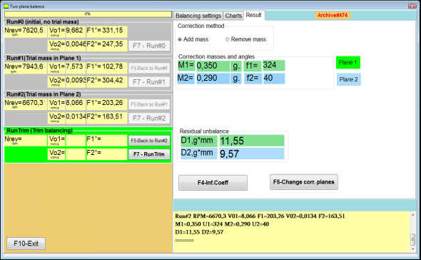
Fig. 7.36. Results of calculation of corrective weights – free position
تصویر 7.37۔ اصلاحی وزن کے حساب کے نتائج – مفت پوزیشن۔ قطبی خاکہ
In the case of using the Weight Attachment Method" – "Fixed positions

تصویر 7.38۔ اصلاحی وزن کے حساب کے نتائج - مقررہ پوزیشن۔
تصویر 7.39۔ اصلاحی وزن کے حساب کے نتائج - مقررہ پوزیشن۔ قطبی خاکہ۔
وزن منسلک کرنے کا طریقہ استعمال کرنے کی صورت میں "-""Circular groove"
تصویر 7.40۔ اصلاحی وزن کے حساب کے نتائج - سرکلر نالی۔
⚠️ توجہ!
- پر پیمائش کے عمل کو مکمل کرنے کے بعد RUN#2 of the balancing machine, stop the rotation of the rotor and remove the trial weight previously installed. Then you can to install (or remove) corrective weights.
- قطبی کوآرڈینیٹ سسٹم میں اصلاحی وزن کی کونیی پوزیشن کو روٹر کی گردش کی سمت میں آزمائشی وزن کی تنصیب کی جگہ سے شمار کیا جاتا ہے۔
- کی صورت میں ""Fixed position""-1st position (Z1), coincides with the place of installation of the trial weight. The counting direction of the position number is in the direction of rotation of the rotor.
- پہلے سے طے شدہ طور پر اصلاحی وزن روٹر میں شامل کیا جائے گا۔ اس کی نشاندہی اس لیبل سے ہوتی ہے جو ""Add"" فیلڈ۔ اگر وزن ہٹا رہے ہیں (مثال کے طور پر، ڈرلنگ کے ذریعے)، تو آپ کو ""Delete"" فیلڈ، جس کے بعد درستی کے وزن کی کونیی پوزیشن خود بخود 180º تک بدل جائے گی۔.
RunC (Trim run)
After installing the correction weight on the balancing rotor it is necessary to carry out a RunC (trim) and evaluate the effectiveness of the performed balancing.
⚠️ توجہ! ٹیسٹ رن پر پیمائش شروع کرنے سے پہلے، مشین کے روٹر کی گردش کو آن کرنا اور اس بات کو یقینی بنانا ضروری ہے کہ یہ آپریٹنگ رفتار میں داخل ہو گیا ہے۔
RunTrim (بیلنس کوالٹی چیک کریں) سیکشن میں وائبریشن پیرامیٹرز کی پیمائش کرنے کے لیے، "پر کلک کریں۔"F7 – RunTrim"بٹن (یا کمپیوٹر کی بورڈ پر F7 بٹن دبائیں)۔.
The results of measuring the rotor rotation frequency (RPM), as well as the value of the RMS component (Vо1) and phase (F1) of 1x vibration will be shown.
""Result"" ٹیب ورکنگ ونڈو کے دائیں جانب پیمائش کے نتائج کے جدول کے ساتھ ظاہر ہوتا ہے، جو اضافی اصلاحی وزن کے پیرامیٹرز کی گنتی کے نتائج دکھاتا ہے۔.
These weights can be added to corrective weights that are already installed on the rotor to compensate for residual imbalance.
In addition, the residual rotor unbalance achieved after balancing is displayed in the lower part of this window.
ایسی صورت میں جب متوازن روٹر کی بقایا کمپن اور/یا بقایا عدم توازن کی قدریں تکنیکی دستاویزات میں قائم رواداری کے تقاضوں کو پورا کرتی ہیں، توازن کا عمل مکمل کیا جا سکتا ہے۔
Otherwise, the balancing process may continue. This allows the method of successive approximations to correct possible errors that may occur during the installation (removal) of the corrective weight on a balanced rotor.
بیلنسنگ روٹر پر بیلنسنگ کے عمل کو جاری رکھتے ہوئے، اضافی اصلاحی ماس کو انسٹال کرنا (ہٹانا) ضروری ہے، جس کے پیرامیٹرز "نتیجہ" ونڈو میں بتائے گئے ہیں۔.
میں ""Result""ونڈو میں دو کنٹرول بٹن استعمال کیے جا سکتے ہیں -""F4-Inf.Coeff", "F5 – Change correction planes".
Influence coefficients (2 planes)
""F4-Inf.Coeff"" بٹن (یا کمپیوٹر کی بورڈ پر F4 فنکشن کلید) کا استعمال کمپیوٹر میموری میں روٹر بیلنسنگ گتانکوں کو دیکھنے اور محفوظ کرنے کے لیے کیا جاتا ہے، جس کا حساب دو انشانکن آغاز کے نتائج سے کیا جاتا ہے۔.
جب اسے دبایا جاتا ہے، ""Influence coefficients (two planes)"کمپیوٹر ڈسپلے پر ورکنگ ونڈو نمودار ہوتی ہے، جس میں پہلے تین کیلیبریشن اسٹارٹس کے نتائج کی بنیاد پر حساب کردہ بیلنسنگ گتانک ظاہر ہوتے ہیں۔.

Fig. 7.41. Working window with balancing coefficients in 2 planes.
مستقبل میں، جب اس قسم کی مشین کے توازن کو سمجھا جاتا ہے، تو اسے استعمال کرنے کی ضرورت ہے ""Saved coeff."موڈ اور بیلنسنگ گتانک کمپیوٹر میموری میں محفوظ ہیں۔.
گتانک کو بچانے کے لیے، کلک کریں ""F9 – Save""بٹن اور جائیں""Influence coefficients archive (2planes)"ونڈوز (تصویر 7.42 دیکھیں)
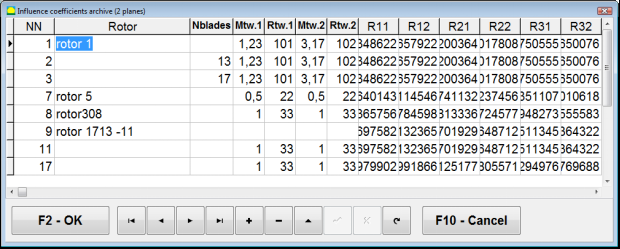
Fig. 7.42. The second page of the working window with balancing coefficients in 2 planes.
Change correction planes
""F5 – Change correction planes"" بٹن اس وقت استعمال کیا جاتا ہے جب اصلاحی طیاروں کی پوزیشن کو تبدیل کرنے کی ضرورت ہو، جب عوام اور تنصیب کے زاویوں کو اصلاحی وزن کا دوبارہ حساب لگانا ضروری ہو۔.
This mode is primarily useful when balancing rotors of complex shape (for example, crankshafts).
جب یہ بٹن دبایا جاتا ہے تو کام کرنے والی ونڈو ""Recalculation of correction weights mass and angle to other correction planes"کمپیوٹر ڈسپلے پر ظاہر ہوتا ہے۔.
In this working window, you should select one of the 4 possible options by clicking corresponding picture.
اصل تصحیح والے طیاروں (Н1 اور Н2) کو سبز اور نئے (K1 اور K2) پر نشان زد کیا گیا ہے، جس کے لیے یہ دوبارہ گنتی ہے، سرخ میں۔
پھر، میں ""Calculation data"" سیکشن میں، مطلوبہ ڈیٹا درج کریں، بشمول:
- متعلقہ تصحیح طیاروں کے درمیان فاصلہ (a, b, c)؛
- روٹر پر اصلاحی وزن کی تنصیب کے ریڈی آئی کی نئی اقدار (R1 ', R2')۔.
ڈیٹا داخل کرنے کے بعد، آپ کو بٹن دبانا ہوگا ""F9-calculate"
اس ورکنگ ونڈو کے متعلقہ حصے میں حساب کے نتائج (ماسس M1, M2 اور اصلاحی وزن f1, f2 کی تنصیب کے زاویے) دکھائے جاتے ہیں۔
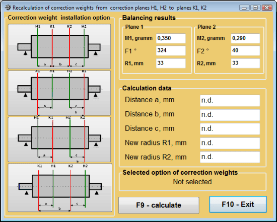
تصویر 7.43 اصلاحی طیاروں کو تبدیل کریں۔ تصحیح کے بڑے پیمانے پر اور زاویہ کو دوسرے اصلاحی طیاروں سے دوبارہ گننا۔
محفوظ شدہ کوف۔ 2 طیاروں میں توازن
Saved coeff. balancing can be performed on a machine for which balancing coefficients have already been determined and saved in the computer memory.
⚠️ توجہ! When re-balancing, the vibration sensors and the phase angle sensor must be installed in the same way as during the initial balancing.
دوبارہ توازن کے لیے ابتدائی ڈیٹا کا ان پٹ شروع ہوتا ہے ""دو ہوائی جہاز کا توازن۔ توازن کی ترتیبات".
اس صورت میں، ""Influence coefficients""سیکشن، منتخب کریں""Saved coeff.""آئٹم۔ اس صورت میں، ونڈو""Influence coefficients archive (2planes)"" ظاہر ہوگا، جس میں پہلے سے طے شدہ بیلنسنگ گتانکوں کا ذخیرہ محفوظ ہے۔.
"►" یا "◄" کنٹرول بٹنوں کا استعمال کرتے ہوئے اس آرکائیو کے ٹیبل میں آگے بڑھتے ہوئے، آپ ہماری دلچسپی کی مشین کے توازن گتانک کے ساتھ مطلوبہ ریکارڈ منتخب کر سکتے ہیں۔ پھر، موجودہ پیمائش میں اس ڈیٹا کو استعمال کرنے کے لیے، دبائیں ""F2 – OK"بٹن اور پچھلی ورکنگ ونڈو پر واپس جائیں۔.
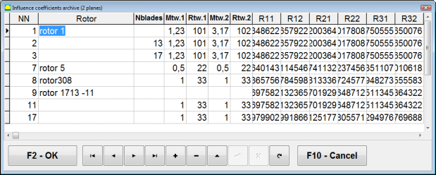
Fig. 7.44. The second page of the working window with balancing coefficients in 2 planes.
اس کے بعد، دیگر تمام ونڈوز کے مواد ""2 پی ایل میں توازن ماخذ ڈیٹا"" خود بخود بھر جاتا ہے۔.
Saved coeff. Balancing
"Saved coeff."توازن کے لیے صرف ایک ٹیوننگ اسٹارٹ اور بیلنسنگ مشین کا کم از کم ایک ٹیسٹ اسٹارٹ درکار ہوتا ہے۔.
Vibration measurement at the tuning start (Run # 0مشین کی ) میں کارکردگی کا مظاہرہ کیا جاتا ہے ""Balancing in 2 planes"توازن کی میز کے ساتھ کام کرنے والی ونڈو کے نتائج میں Run # 0 section.
⚠️ توجہ! Before starting the measurement, it is necessary to turn on the rotation of the rotor of the balancing machine and make sure that it has entered the operating mode with a stable speed.
To measure vibration parameters in the Run # 0 سیکشن، "پر کلک کریں"F7 – Run#0"بٹن (یا کمپیوٹر کی بورڈ پر F7 بٹن دبائیں)۔.
The results of measuring the rotor speed (RPM), as well as the value of the components of the RMS (VО1, VО2) and phases (F1, F2) of the 1x vibration appear in the corresponding fields of the Run # 0 section.
ایک ہی وقت میں، ""Result"" ٹیب کھلتا ہے، جو اصلاحی وزن کے پیرامیٹرز کا حساب لگانے کے نتائج دکھاتا ہے جو اس کے عدم توازن کی تلافی کے لیے روٹر پر نصب ہونا ضروری ہے۔.
مزید برآں، پولر کوآرڈینیٹ سسٹم کے استعمال کی صورت میں، ڈسپلے بڑے پیمانے پر اقدار اور اصلاحی وزن کی تنصیب کے زاویے دکھاتا ہے۔
In the case of decomposition of corrective weights on the blades, the numbers of the blades of the balancing rotor and the mass of weight that need to be installed on them are displayed.
Further, the balancing process is carried out in accordance with the recommendations set out in section 7.6.1.2. for primary balancing.
⚠️ توجہ!
- After completion of the measurement process after the second start of the balanced machine stop the rotation of its rotor and remove the previously set trial weight. Only then you can begin to install (or remove) correction weight on the rotor.
- Counting the angular position of the place of adding (or removing) of the correction weight from the rotor is carried out on the installation site of trial weight in the polar coordinate system. Counting direction coincides with the direction of the angle of rotor rotation.
- بلیڈز پر توازن کی صورت میں - متوازن روٹر بلیڈ، جسے پوزیشن 1 کے طور پر نامزد کیا گیا ہے، آزمائشی وزن کی تنصیب کی جگہ کے ساتھ موافق ہے۔ کمپیوٹر ڈسپلے پر دکھائے گئے بلیڈ کا حوالہ نمبر سمت روٹر کی گردش کی سمت میں انجام دیا جاتا ہے۔
- پروگرام کے اس ورژن میں یہ پہلے سے طے شدہ طور پر قبول کیا جاتا ہے کہ روٹر پر اصلاحی وزن شامل کیا جائے گا۔ فیلڈ "اضافہ" میں قائم کردہ ٹیگ اس کی گواہی دیتا ہے۔ کسی وزن کو ہٹانے کے ذریعے عدم توازن کو درست کرنے کی صورت میں (مثال کے طور پر ڈرلنگ کے ذریعے) "ریموول" کے میدان میں ٹیگ لگانا ضروری ہے تو درست وزن کی کونیی پوزیشن 180º پر خود بخود بدل جائے گی۔.
مینڈریل سنکیت کا خاتمہ (انڈیکس توازن) - دو طیارے
If during balancing the rotor is installed in a cylindrical mandrel, then the eccentricity of the mandrel may introduce an additional error. To eliminate this error, the rotor should be deployed in the mandrel 180 degrees and carry out an additional start. This is called index balancing.
To carry out index balancing, a special option is provided in the Balanset-1A program. When checked Mandrel eccentricity elimination an additional RunEcc section appears in the balancing window.
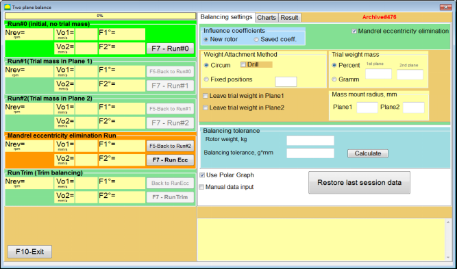
Fig. 7.45. The working window for Index balancing.
After running Run # 2 (Trial mass Plane 2), a window will appear
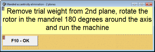
Fig. 7.46. Attention windows
روٹر کو 180° موڑ کے ساتھ انسٹال کرنے کے بعد، Ecc چلائیں مکمل کرنا ضروری ہے۔ پروگرام خود بخود روٹر کے حقیقی عدم توازن کا حساب لگائے گا بغیر مینڈرل سنکی کو متاثر کیے۔
7.6 چارٹس وضع
"چارٹس" موڈ میں کام کرنا ابتدائی ونڈو سے شروع ہوتا ہے (دیکھیں تصویر 7.1) "دبائیں۔"F8 - چارٹس۔ پھر ایک ونڈو کھلتی ہے "دو چینلز پر کمپن کی پیمائش۔ چارٹس" (دیکھیں تصویر 7.19)۔.

تصویر 7.47۔ آپریٹنگ ونڈو "دو چینلز پر کمپن کی پیمائش۔ چارٹس"۔.
While working in this mode it is possible to plot four versions of vibration chart.
The first version allows to get a timeline function of the overall vibration (of vibration velocity) on the first and second measuring channels.
The second version allows you to get graphs of vibration (of vibration velocity), which occurs on rotation frequency and its higher harmonical components.
These graphs are obtained as a result of the synchronous filtering of the overall vibration time function.
The third version provides vibration charts with the results of the harmonical analysis.
The fourth version allows to get a vibration chart with the results of the spectrum analysis.
مجموعی کمپن کے چارٹس
آپریٹنگ ونڈو میں مجموعی وائبریشن چارٹ بنانے کے لیے ""Measurement of vibration on two channels. Charts""آپریٹنگ موڈ کو منتخب کرنا ضروری ہے""overall vibration""مناسب بٹن پر کلک کرکے۔ پھر باکس میں کمپن کی پیمائش کو "دورانیہ، سیکنڈ میں" بٹن پر کلک کرکے سیٹ کریں "▼" اور ڈراپ ڈاؤن فہرست سے پیمائش کے عمل کی مطلوبہ مدت منتخب کریں، جو کہ 1، 5، 10، 15 یا 20 سیکنڈز کے برابر ہوسکتی ہے۔;
تیاری پر دبائیں (کلک کریں) ""F9- پیمائش" بٹن پھر کمپن کی پیمائش کا عمل بیک وقت دو چینلز پر شروع ہوتا ہے۔.
After completion of the measurement process in the operating window appear charts of time function of the overall vibration of the first (red) and the second (green) channels (see. Fig. 7.47).
On these charts time is plotted on X-axis and the amplitude of the vibration velocity (mm/sec) is plotted on Y-axis.
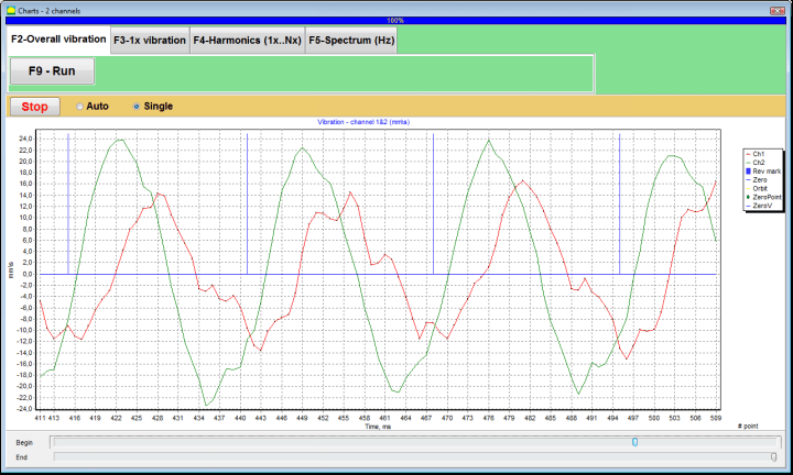
تصویر 7.48۔ مجموعی وائبریشن چارٹس کے ٹائم فنکشن کے آؤٹ پٹ کے لیے آپریٹنگ ونڈو
There are also marks (blue-colored) in these graphs connecting charts of overall vibration with the rotation frequency of the rotor. In addition, each mark indicates beginning (end) of the next revolution of the rotor.
In need of the scale change of the chart on X-axis the slider, pointed by an arrow on fig. 7.20, can be used.
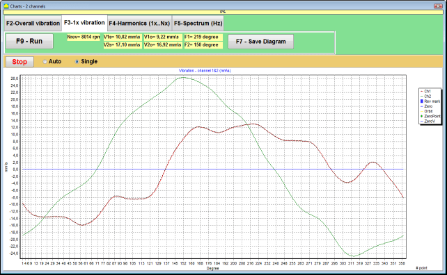
1x کمپن کے چارٹس
آپریٹنگ ونڈو میں 1x وائبریشن چارٹ بنانے کے لیے ""Measurement of vibration on two channels. Charts""آپریٹنگ موڈ کو منتخب کرنا ضروری ہے""1x vibration""مناسب بٹن پر کلک کرکے۔.
پھر آپریٹنگ ونڈو "1x کمپن" ظاہر ہوتا ہے۔.
دبائیں (کلک کریں) ""F9- پیمائش" بٹن پھر کمپن کی پیمائش کا عمل بیک وقت دو چینلز پر شروع ہوتا ہے۔.
تصویر 7.49۔ 1x وائبریشن چارٹس کے آؤٹ پٹ کے لیے آپریٹنگ ونڈو۔
After completion of the measurement process and mathematical calculation of results (synchronous filtering of the time function of the overall vibration) on display in the main window on a period equal to one revolution of the rotor appear charts of the 1x vibration on two channels.
In this case, a chart for the first channel is depicted in red and for the second channel in green. On these charts angle of the rotor revolution is plotted (from mark to mark) on X-axis and the amplitude of the vibration velocity (mm/sec) is plotted on Y-axis.
اس کے علاوہ، ورکنگ ونڈو کے اوپری حصے میں (بٹن کے دائیں طرف""F9 - پیمائش کریں۔"") دونوں چینلز کی وائبریشن پیمائش کی عددی قدریں، جو ہمیں ""Vibration meter""موڈ، دکھائے جاتے ہیں۔.
In particular: RMS value of the overall vibration (V1s, V2s), the magnitude of RMS (V1o, V2o) and phase (Fi, Fj) of the 1x vibration and rotor speed (Nrev).
ہارمونیکل تجزیہ کے نتائج کے ساتھ وائبریشن چارٹس
آپریٹنگ ونڈو میں ہارمونیکل تجزیہ کے نتائج کے ساتھ ایک چارٹ تیار کرنا ""Measurement of vibration on two channels. Charts""آپریٹنگ موڈ کو منتخب کرنا ضروری ہے""Harmonical analysis""مناسب بٹن پر کلک کرکے۔.
اس کے بعد عارضی فنکشن کے چارٹ اور کمپن ہارمونیکل پہلوؤں کے سپیکٹرم کے بیک وقت آؤٹ پٹ کے لیے ایک آپریٹنگ ونڈو ظاہر ہوتا ہے جس کا دورانیہ روٹر گردش کی فریکوئنسی کے برابر یا ایک سے زیادہ ہے۔
Attention!
When operating in this mode it is necessary to use the phase angle sensor which synchronizes the measurement process with the rotor frequency of the machines to which the sensor is set.
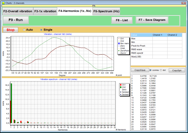
تصویر 7.50۔ 1x کمپن کی آپریٹنگ ونڈو ہارمونکس۔
تیاری پر دبائیں (کلک کریں) ""F9- پیمائش" بٹن پھر کمپن کی پیمائش کا عمل بیک وقت دو چینلز پر شروع ہوتا ہے۔.
آپریٹنگ ونڈو میں پیمائش کے عمل کی تکمیل کے بعد ٹائم فنکشن (اعلی چارٹ) کے چارٹ اور 1x کمپن (نچلے چارٹ) کے ہارمونکس نظر آتے ہیں۔
The number of harmonic components is plotted on X-axis and RMS of the vibration velocity (mm/sec) is plotted on Y-axis.
وائبریشن ٹائم ڈومین اور سپیکٹرم کے چارٹس
سپیکٹرم چارٹ بنانے کے لیے استعمال کریں ""F5-سپیکٹرم""ٹیب:
پھر لہر کے چارٹ اور کمپن کے سپیکٹرم کے بیک وقت آؤٹ پٹ کے لئے ایک آپریٹنگ ونڈو ظاہر ہوتا ہے۔

تصویر 7.51۔ کمپن کے سپیکٹرم کے آؤٹ پٹ کے لیے آپریٹنگ ونڈو۔
تیاری پر دبائیں (کلک کریں) ""F9- پیمائش" بٹن پھر کمپن کی پیمائش کا عمل بیک وقت دو چینلز پر شروع ہوتا ہے۔.
آپریٹنگ ونڈو میں پیمائش کے عمل کی تکمیل کے بعد ٹائم فنکشن (اعلی چارٹ) اور کمپن کے سپیکٹرم (نچلے چارٹ) کے چارٹ ظاہر ہوتے ہیں۔
The vibration frequency is plotted on X-axis and RMS of the vibration velocity (mm/sec) is plotted on Y-axis.
In this case, a chart for the first channel is depicted in red and for the second channel in green.
8. آلہ کے آپریشن اور دیکھ بھال کے بارے میں عمومی ہدایات
8.1 توازن کے معیار کا معیار (ISO 2372 سٹینڈرڈ)
آئی ایس او 2372 اسٹینڈرڈ کے ذریعے قائم وائبریشن لیولز کے ذریعے توازن کے معیار کا اندازہ لگایا جا سکتا ہے۔ نیچے دی گئی جدول مشین کی مختلف کلاسوں کے لیے قابل قبول وائبریشن لیولز دکھاتی ہے۔
| مشین کلاس | اچھی (ملی میٹر/سیکنڈ RMS) |
قابل قبول (ملی میٹر/سیکنڈ RMS) |
پھر بھی قابل قبول ہے۔ (ملی میٹر/سیکنڈ RMS) |
ناقابل قبول (ملی میٹر/سیکنڈ RMS) |
|---|---|---|---|---|
| کلاس 1 سخت بنیادوں پر چھوٹی مشینیں۔ (15 کلو واٹ تک کی موٹریں) |
<0.7 | 0.7 - 1.8 | 1.8 - 4.5 | > 4.5 |
| کلاس 2 بنیادوں کے بغیر درمیانی مشینیں۔ (15-75 کلو واٹ موٹرز)، 300 کلو واٹ تک ڈرائیو میکانزم |
< 1.1 | 1.1 - 2.8 | 2.8 - 7.1 | > 7.1 |
| کلاس 3 سخت بنیادوں پر بڑی مشینیں۔ (300 کلو واٹ سے زیادہ کا سامان) |
<1.8 | 1.8 - 4.5 | 4.5 - 11 | > 11 |
| کلاس 4 ہلکی پھلکی بنیادوں پر بڑی مشینیں۔ (300 کلو واٹ سے زیادہ کا سامان) |
<2.8 | 2.8 - 7.1 | 7.1 - 18 | > 18 |
نوٹ: یہ اقدار توازن کے معیار کا جائزہ لینے کے لیے رہنمائی فراہم کرتی ہیں۔ ہمیشہ اپنی درخواست کے لیے مخصوص سازوسامان بنانے والے کی وضاحتیں اور قابل اطلاق معیارات کا حوالہ دیں۔
8.2 دیکھ بھال کے تقاضے
🔧 باقاعدہ دیکھ بھال
- ✓مینوفیکچرر کی وضاحتوں کے مطابق سینسر کی باقاعدہ انشانکن
- ✓سینسرز کو صاف اور مقناطیسی ملبے سے پاک رکھیں
- ✓جب استعمال میں نہ ہو تو حفاظتی کیس میں سامان کو اسٹور کریں۔
- ✓لیزر سینسر کو دھول اور نمی سے بچائیں۔
- ✓پہننے یا نقصان کے لیے کیبل کنکشن کو باقاعدگی سے چیک کریں۔
- ✓کارخانہ دار کی تجویز کے مطابق سافٹ ویئر کو اپ ڈیٹ کریں۔
- ✓اہم بیلنسنگ ڈیٹا کی بیک اپ کاپیاں رکھیں
📋 EU دیکھ بھال کے معیارات
سامان کی دیکھ بھال کے لیے ضروری ہے کہ:
- EN ISO 9001: کوالٹی مینجمنٹ سسٹم کی ضروریات
- EN 13306: بحالی کی اصطلاحات اور تعریفیں۔
- EN 15341: بحالی کے کلیدی کارکردگی کے اشارے
- EU مشینری کی ہدایت کے مطابق باقاعدگی سے حفاظتی معائنہ
ضمیمہ 1. روٹر بیلنسنگ
روٹر ایک ایسا جسم ہے جو ایک مخصوص محور کے گرد گھومتا ہے اور اس کی بیئرنگ سطحوں کے ذریعہ سپورٹ میں رکھا جاتا ہے۔ روٹر کی بیئرنگ سطحیں رولنگ یا سلائیڈنگ بیرنگ کے ذریعے وزن کو سپورٹ تک منتقل کرتی ہیں۔ "بیرنگ سطح" کی اصطلاح استعمال کرتے ہوئے ہم صرف جرنل* یا جرنل کی جگہ لینے والی سطحوں کا حوالہ دیتے ہیں۔.
*جرنل (جرمن میں زپفن "جرنل"، "پن" کے لیے) - شافٹ یا محور کا ایک حصہ ہے، جسے ہولڈر (بیرنگ باکس) لے جا رہا ہے۔.
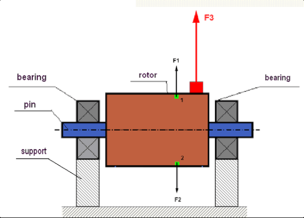
fig.1 Rotor and centrifugal forces.
In a perfectly balanced rotor, its mass is distributed symmetrically regarding the axis of the rotation. This means that any element of the rotor can correspond to another element located symmetrically in a relation to the axis of the rotation. During rotation, each rotor element acts upon by a centrifugal force directed in the radial direction (perpendicular to the axis of the rotor rotation). In a balanced rotor, the centrifugal force influencing any element of the rotor is balanced by the centrifugal force that influences the symmetrical element. For example, elements 1 and 2 (shown in fig.1 and colored in green) are influenced by centrifugal forces F1 and F2: equal in value and absolutely opposite in directions. This is true for all symmetrical elements of the rotor and thus the total centrifugal force influencing the rotor is equal to 0 the rotor is balanced. But if the symmetry of the rotor is broken (in Figure 1, the asymmetric element is marked in red), then the unbalanced centrifugal force F3 begins to act on the rotor.
گھومنے پر، یہ قوت روٹر کی گردش کے ساتھ مل کر سمت بدلتی ہے۔ اس قوت کے نتیجے میں پیدا ہونے والا متحرک بوجھ بیرنگز میں منتقل ہو جاتا ہے، جو ان کے تیز لباس کی طرف جاتا ہے۔ اس کے علاوہ، اس متغیر قوت کے زیر اثر، سپورٹ اور فاؤنڈیشن جس پر روٹر لگا ہوا ہے، کی ایک چکراتی خرابی ہوتی ہے، جو کمپن پیدا کرتی ہے۔ روٹر کے عدم توازن اور اس کے ساتھ آنے والی وائبریشن کو ختم کرنے کے لیے ضروری ہے کہ توازن رکھنے والے ماسز کو سیٹ کیا جائے، جو روٹر کی ہم آہنگی کو بحال کرے گا۔
Rotor balancing is an operation to eliminate imbalance by adding balancing masses.
The task of balancing is to find the value and places (angle) of the installation of one or more balancing masses.
روٹرز اور عدم توازن کی اقسام
Considering the strength of the rotor material and the magnitude of the centrifugal forces influencing it, the rotors can be divided into two types: rigid and flexible.
سنٹری فیوگل فورس کے زیر اثر آپریٹنگ حالات میں سخت روٹرز قدرے بگڑ سکتے ہیں لیکن حسابات میں اس اخترتی کے اثر کو اس لیے نظرانداز کیا جا سکتا ہے۔
Deformation of flexible rotors on the other hand should never be neglected. The deformation of flexible rotors complicates the solution for the balancing problem and requires the use of some other mathematical models in comparison with the task of balancing rigid rotors. It is important to mention that the same rotor at low speeds of rotation can behave like rigid one and at high speeds it will behave like flexible one. Further on we will consider the balancing of rigid rotors only.
روٹر کی لمبائی کے ساتھ غیر متوازن عوام کی تقسیم پر منحصر ہے، دو قسم کے عدم توازن کو الگ کیا جا سکتا ہے - جامد اور متحرک۔ یہی بات جامد اور متحرک روٹر کے توازن پر بھی لاگو ہوتی ہے۔
روٹر کا جامد عدم توازن روٹر کی گردش کے بغیر ہوتا ہے۔ دوسرے لفظوں میں، جب روٹر کشش ثقل کے زیر اثر ہوتا ہے تو یہ خاموش ہوتا ہے اور اس کے علاوہ یہ "ہیوی پوائنٹ" کو نیچے کر دیتا ہے۔ جامد عدم توازن کے ساتھ روٹر کی ایک مثال تصویر 2 میں پیش کی گئی ہے۔

Fig.2
The dynamic imbalance occurs only when the rotor spins.
An example of a rotor with the dynamic imbalance is presented in Fig.3.
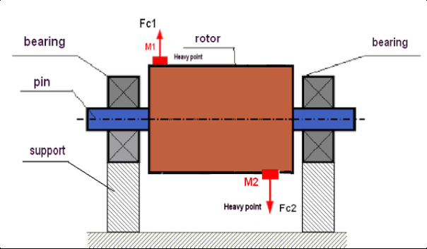
Fig.3. Dynamic imbalance of rotor – couple of the centrifugal forces
اس صورت میں، غیر متوازن مساوی ماس M1 اور M2 مختلف سطحوں میں - روٹر کی لمبائی کے ساتھ مختلف جگہوں پر واقع ہیں۔ جامد پوزیشن میں، یعنی جب روٹر نہیں گھومتا ہے، روٹر صرف کشش ثقل سے متاثر ہو سکتا ہے اور اس وجہ سے ماس ایک دوسرے کو متوازن رکھیں گے۔ حرکیات میں جب روٹر گھوم رہا ہوتا ہے، ماس M1 اور M2 سینٹرفیوگل فورسز FЎ1 اور FЎ2 سے متاثر ہونا شروع کر دیتے ہیں۔ یہ قوتیں قدر میں برابر ہیں اور سمت میں مخالف ہیں۔ تاہم، چونکہ وہ شافٹ کی لمبائی کے ساتھ مختلف جگہوں پر واقع ہیں اور ایک ہی لائن پر نہیں ہیں، فورسز ایک دوسرے کو معاوضہ نہیں دیتے ہیں۔ FЎ1 اور FЎ2 کی قوتیں روٹر پر عمل کرنے والا ایک لمحہ بناتی ہیں۔ اسی لیے اس عدم توازن کا دوسرا نام ""لمحاتی‘‘ ہے۔ اس کے مطابق، غیر معاوضہ سینٹری فیوگل قوتیں بیئرنگ سپورٹ پر کام کرتی ہیں، جو ان قوتوں سے کافی حد تک بڑھ سکتی ہیں جن پر ہم نے بھروسہ کیا تھا اور بیرنگ کی سروس لائف کو بھی کم کر سکتی ہے۔.
چونکہ اس قسم کا عدم توازن صرف روٹر گھومنے کے دوران ڈائنامکس میں ہوتا ہے، اس لیے اسے ڈائنامک کہا جاتا ہے۔ اسے جامد توازن (یا نام نہاد "چھریوں پر") یا کسی دوسرے اسی طرح کے طریقوں سے ختم نہیں کیا جا سکتا۔ متحرک عدم توازن کو ختم کرنے کے لیے ضروری ہے کہ دو معاوضہ وزن مقرر کیے جائیں جو M1 اور M2 کے ماسز سے پیدا ہونے والے لمحے کی قدر کے برابر اور مخالف سمت پیدا کریں۔ ضروری نہیں کہ معاوضہ دینے والے ماسز M1 اور M2 کے مخالف نصب کیے جائیں اور قیمت میں ان کے برابر ہوں۔ سب سے اہم بات یہ ہے کہ وہ ایک ایسا لمحہ بناتے ہیں جو عدم توازن کے لمحے میں پوری طرح سے معاوضہ دیتا ہے۔.
عام طور پر، بڑے پیمانے پر M1 اور M2 ایک دوسرے کے برابر نہیں ہوسکتے ہیں، لہذا جامد اور متحرک عدم توازن کا ایک مجموعہ ہوگا. یہ نظریاتی طور پر ثابت ہے کہ ایک سخت روٹر کے عدم توازن کو ختم کرنے کے لیے روٹر کی لمبائی کے ساتھ دو وزن نصب کرنا ضروری اور کافی ہے۔ یہ وزن متحرک عدم توازن کے نتیجے میں پیدا ہونے والے لمحے اور روٹر محور (جامد عدم توازن) کے نسبت بڑے پیمانے پر عدم توازن کے نتیجے میں بننے والی سینٹرفیوگل قوت دونوں کی تلافی کریں گے۔ ہمیشہ کی طرح متحرک عدم توازن لمبے روٹرز کے لیے عام ہے، جیسے شافٹ، اور جامد - تنگ کے لیے۔ تاہم، اگر تنگ روٹر کو محور کے حوالے سے ترچھا نصب کیا گیا ہو، یا اس سے بھی بدتر، درست شکل (نام نہاد "وہیل wobbles")، تو اس صورت میں متحرک عدم توازن کو ختم کرنا مشکل ہو جائے گا (تصویر 4 دیکھیں)، اس حقیقت کی وجہ سے کہ درست وزن کا تعین کرنا مشکل ہے، جو صحیح معاوضہ کا لمحہ پیدا کرتا ہے۔.
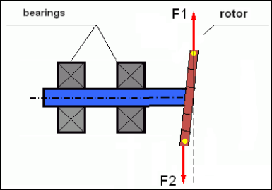
Fig.4 Dynamic balancing of the wobbling wheel
چونکہ تنگ روٹر کا کندھا ایک مختصر لمحہ پیدا کرتا ہے، اس لیے اسے بڑے پیمانے پر وزن درست کرنے کی ضرورت پڑ سکتی ہے۔ لیکن ایک ہی وقت میں ایک اضافی نام نہاد "حوصلہ افزائی عدم توازن" ہے جو درست کرنے والے عوام سے سینٹرفیوگل قوتوں کے زیر اثر تنگ روٹر کی خرابی سے وابستہ ہے۔.
See the example:
""سخت روٹرز کے توازن پر طریقہ کار کی ہدایات"" ISO 1940-1:2003 Mechanical vibration – Balance quality requirements for rotors in a constant (rigid) state – Part 1: Specification and verification of balance tolerances
This is visible for narrow fan wheels, which, in addition to the power imbalance, also influences an aerodynamic imbalance. And it is important to bear in mind that the aerodynamic imbalance, in fact the aerodynamic force, is directly proportional to the angular velocity of the rotor, and to compensate it, the centrifugal force of the correcting mass is used, which is proportional to the square of the angular velocity. Therefore, the balancing effect may only occur at a specific balancing frequency. At other speeds there would be an additional gap. The same can be said about electromagnetic forces in an electromagnetic motor, which are also proportional to the angular velocity. In other words it is impossible to eliminate all causes of vibration of the mechanism by any means of balancing.
کمپن کے بنیادی اصول
کمپن میکانزم ڈیزائن کا ایک رد عمل ہے جو سائیکلک اتیجیت قوت کے اثر سے ہوتا ہے۔ یہ قوت مختلف نوعیت کی ہو سکتی ہے۔
- روٹر کے عدم توازن کی وجہ سے پیدا ہونے والی سینٹرفیوگل فورس ایک غیر معاوضہ قوت ہے جو "بھاری نقطہ" کو متاثر کرتی ہے۔ خاص طور پر یہ قوت اور اس سے پیدا ہونے والی کمپن بھی روٹر کے توازن سے ختم ہو جاتی ہے۔.
- باہم تعامل کرنے والی قوتیں، جن کی نوعیت "جیومیٹرک" ہوتی ہے اور ملن حصوں کی تیاری اور تنصیب میں غلطیوں سے پیدا ہوتی ہے۔ یہ قوتیں ہو سکتی ہیں، مثال کے طور پر، شافٹ جرنل کے غیر گول ہونے، گیئرز میں دانتوں کے پروفائلز میں خرابی، بیئرنگ ریس ویز کی لہر، میٹنگ شافٹ کی غلط ترتیب وغیرہ کی وجہ سے۔ گردنوں کے گول نہ ہونے کی صورت میں، شافٹ کا محور شافٹ کے زاویہ کے لحاظ سے بدل جائے گا۔ اگرچہ یہ کمپن روٹر کی رفتار سے ظاہر ہوتی ہے، لیکن توازن کے ساتھ اسے ختم کرنا تقریباً ناممکن ہے۔.
- Aerodynamic forces arising from the rotation of the impeller fans and other blade mechanisms. Hydrodynamic forces arising from the rotation of hydraulic pump impellers, turbines, etc.
- برقی مشینوں کے آپریشن کے نتیجے میں پیدا ہونے والی برقی مقناطیسی قوتیں، مثال کے طور پر، روٹر وائنڈنگز کی عدم توازن کی وجہ سے، شارٹ سرکیٹ موڑ کی موجودگی وغیرہ۔
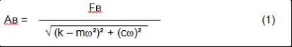
The magnitude of vibration (for example, its amplitude AB) depends not only on the magnitude of the excitation force Fт acting on the mechanism with the circular frequency ω, but also on the stiffness k of the structure of the mechanism, its mass m, and damping coefficient C.
Various types of sensors can be used to measure vibration and balance mechanisms, including:
- absolute vibration sensors designed to measure vibration acceleration (accelerometers) and vibration velocity sensors;
- رشتہ دار وائبریشن سینسر ایڈی کرنٹ یا کیپسیٹیو، کمپن کی پیمائش کے لیے ڈیزائن کیا گیا ہے۔
In some cases (when the structure of the mechanism allows it) sensors of force can also be used to examine its vibration weight.
Particularly, they are widely used to measure the vibration weight of the supports of hardbearing balancing machines.
Therefore vibration is the reaction of the mechanism to the influence of external forces. The amount of vibration depends not only on the magnitude of the force acting on the mechanism, but also on the rigidity of the mechanism. Two forces with the same magnitude can lead to different vibrations. In mechanisms with a rigid support structure, even with the small vibration, the bearing units can be significantly influenced by dynamic weights. Therefore, when balancing mechanisms with stiff legs apply the force sensors, and vibration (vibro accelerometers). Vibration sensors are only used on mechanisms with relatively pliable supports, right when the action of unbalanced centrifugal forces leads to a noticeable deformation of the supports and vibration. Force sensors are used in rigid supports even when significant forces arising from imbalance do not lead to significant vibration.
ساخت کی گونج
We have previously mentioned that rotors are divided into rigid and flexible. The rigidity or flexibility of the rotor should not be confused with the stiffness or mobility of the supports (foundation) on which the rotor is located. The rotor is considered rigid when its deformation (bending) under the action of centrifugal forces can be neglected. The deformation of the flexible rotor is relatively large: it cannot be neglected.
اس مضمون میں ہم صرف سخت روٹرز کے توازن کا مطالعہ کرتے ہیں۔ اپنی باری میں سخت (غیر درست) روٹر سخت یا حرکت پذیر (ناراض) سپورٹ پر واقع ہوسکتا ہے۔ یہ واضح ہے کہ سپورٹ کی یہ سختی/متحرک روٹر کی گردش کی رفتار اور نتیجے میں پیدا ہونے والی سینٹرفیوگل قوتوں کی شدت پر منحصر ہے۔ روایتی بارڈر روٹر سپورٹ/فاؤنڈیشن کے فری دولن کی فریکوئنسی ہے۔ مکینیکل سسٹمز کے لیے، فری oscillations کی شکل اور تعدد کا تعین میکانی نظام کے عناصر کے بڑے پیمانے اور لچک سے کیا جاتا ہے۔ یعنی، قدرتی دولوں کی فریکوئنسی میکانی نظام کی اندرونی خصوصیت ہے اور بیرونی قوتوں پر منحصر نہیں ہے۔ توازن کی حالت سے منحرف ہونے کی وجہ سے، سپورٹ لچکدار ہونے کی وجہ سے اپنی توازن کی پوزیشن پر واپس آ جاتا ہے۔ لیکن بڑے پیمانے پر روٹر کی جڑت کی وجہ سے، یہ عمل گیلے دولن کی نوعیت میں ہے۔ یہ دوغلے روٹر سپورٹ سسٹم کے اپنے دوغلے ہیں۔ ان کی تعدد روٹر ماس کے تناسب اور سپورٹ کی لچک پر منحصر ہے۔
When the rotor begins to rotate and the frequency of its rotation approaches the frequency of its own oscillations, the vibration amplitude increases sharply, which can even lead to the destruction of the structure.
There is a phenomenon of mechanical resonance. In the resonance region, a change in the speed of rotation by 100 rpm can lead to an increase in a vibration tenfold. In this case (in the resonance region) the vibration phase changes by 180°.
اگر میکانزم کا ڈیزائن خراب طریقے سے ڈیزائن کیا گیا ہے، اور روٹر کی آپریٹنگ رفتار دولن کی قدرتی فریکوئنسی کے قریب ہے، تو میکانزم کا کام ناقابل قبول حد تک زیادہ کمپن کی وجہ سے ناممکن ہو جاتا ہے۔ معیاری توازن کے طریقے بھی ناممکن ہیں، کیونکہ گردش کی رفتار میں معمولی تبدیلی کے باوجود بھی پیرامیٹر ڈرامائی طور پر تبدیل ہو جاتے ہیں۔ گونج کے توازن کے میدان میں خاص طریقے استعمال کیے جاتے ہیں لیکن اس مضمون میں انہیں اچھی طرح سے بیان نہیں کیا گیا ہے۔ آپ رن آؤٹ پر میکانزم کے قدرتی دولن کی فریکوئنسی کا تعین کر سکتے ہیں (جب روٹر بند ہو جاتا ہے) یا جھٹکے کے نظام کے ردعمل کے بعد کے اسپیکٹرل تجزیہ کے ساتھ اثر کے ذریعے۔ "Balanset-1" ان طریقوں سے میکانی ساخت کی قدرتی تعدد کا تعین کرنے کی صلاحیت فراہم کرتا ہے۔.
For mechanisms whose operating speed is higher than the resonance frequency, that is, operating in the resonant mode, supports are considered as mobile ones and vibration sensors are used to measure, mainly vibration accelerometers that measure the acceleration of structural elements. For mechanisms operating in hard bearing mode, supports are considered as rigid. In this case, force sensors are used.
مکینیکل سسٹم کے لکیری اور نان لائنر ماڈل
Mathematical models (linear) are used for calculations when balancing rigid rotors. The linearity of the model means that one model is directly proportionally (linearly) dependent on the other. For example, if the uncompensated mass on the rotor is doubled, then the vibration value will be doubled correspondingly. For rigid rotors you can use a linear model because such rotors are not deformed. It is no longer possible to use a linear model for flexible rotors. For a flexible rotor, with an increase of the mass of a heavy point during rotation, an additional deformation will occur, and in addition to the mass, the radius of the heavy point will also increase. Therefore, for a flexible rotor, the vibration will more than double, and the usual calculation methods will not work. Also, a violation of the linearity of the model can lead to a change in the elasticity of the supports at their large deformations, for example, when small deformations of the supports work some structural elements, and when large in the work include other structural elements. Therefore it is impossible to balance the mechanisms that are not fixed at the base, and, for example, are simply established on a floor. With significant vibrations, the unbalance force can detach the mechanism from the floor, thereby significantly changing the stiffness characteristics of the system. The engine legs must be securely fastened, bolted fasteners tightened, the thickness of the washers must provide sufficient rigidity, etc. With broken bearings, a significant displacement of the shaft and its impacts is possible, which will also lead to a violation of linearity and the impossibility of carrying out high-quality balancing.
Methods and devices for balancing
As mentioned above, balancing is the process of combining the main Central axis of inertia with the axis of rotation of the rotor.
The specified process can be executed in two ways.
The first method involves the processing of the rotor axles, which is performed in such a way that the axis passing through the centers of the section of the axles with the main Central axis of inertia of the rotor. This technique is rarely used in practice and will not be discussed in detail in this article.
The second (most common) method involves moving, installing or removing corrective masses on the rotor, which are placed in such a way that the axis of inertia of the rotor is as close as possible to the axis of its rotation.
Moving, adding or removing corrective masses during balancing can be done using a variety of technological operations, including: drilling, milling, surfacing, welding, screwing or unscrewing screws, burning with a laser beam or electron beam, electrolysis, electromagnetic welding, etc.
The balancing process can be performed in two ways:
- متوازن روٹرز اسمبلی (اس کے اپنے بیرنگ میں)؛
- بیلنسنگ مشینوں پر روٹرز کا توازن
To balance the rotors in their own bearings we usually use specialized balancing devices (kits), which allows us to measure the vibration of the balanced rotor at the speed of its rotation in a vector form, i.e. to measure both the amplitude and phase of vibration.
Currently, these devices are manufactured on the basis of microprocessor technology and (in addition to the measurement and analysis of vibration) provide automated calculation of the parameters of corrective weights that must be installed on the rotor to compensate its imbalance.
These devices include:
- کمپیوٹر یا صنعتی کنٹرولر کی بنیاد پر بنایا گیا پیمائش اور کمپیوٹنگ یونٹ؛
- دو (یا زیادہ) کمپن سینسر؛
- فیز اینگل سینسر؛
- سہولت پر سینسر کی تنصیب کا سامان؛
- ایک، دو یا دو سے زیادہ تصحیح کے طیاروں میں روٹر کے عدم توازن کے پیرامیٹرز کی پیمائش کا مکمل سائیکل انجام دینے کے لیے ڈیزائن کردہ خصوصی سافٹ ویئر۔
بیلنسنگ مشینوں پر روٹرز کو بیلنس کرنے کے لیے ایک خصوصی بیلنسنگ ڈیوائس (مشین کا ماپنے کا نظام) کے علاوہ روٹر کو سپورٹ پر انسٹال کرنے اور ایک مقررہ رفتار سے اس کی گردش کو یقینی بنانے کے لیے ایک "ان وائنڈنگ میکانزم" کا ہونا ضروری ہے۔.
Currently, the most common balancing machines exist in two types:
- زیادہ گونج والا (کومل سپورٹ کے ساتھ)؛
- سخت بیئرنگ (سخت سپورٹ کے ساتھ)۔
Over-resonant machines have a relatively pliable supports, made, for example, on the basis of the flat springs.
The natural oscillation frequency of these supports is usually 2-3 times lower than the speed of the balanced rotor, which is mounted on them.
Vibration sensors (accelerometers, vibration velocity sensors, etc.) are usually used to measure the vibration of the supports of a resonant machine.
In the hardbearing balancing machines are used relatively-rigid supports, natural oscillation frequencies of which should be 2-3 times higher than the speed of the balanced rotor.
Force sensors are usually used to measure the vibration weight on the supports of the machine.
The advantage of the hard bearing balancing machines is that they can be balanced at relatively low rotor speeds (up to 400-500 rpm), which greatly simplifies the design of the machine and its foundation, as well as increases the productivity and safety of balancing.
Balancing technique
⚠️ توازن صرف اس کمپن کو ختم کرتا ہے جو اس کے گردش کے محور کے نسبت روٹر ماس ڈسٹری بیوشن کی غیر متناسب ہونے کی وجہ سے ہوتا ہے۔ دوسرے قسم کے کمپن کو توازن کے ذریعے ختم نہیں کیا جا سکتا!
Balancing is the subject to technically serviceable mechanisms, the design of which ensures the absence of resonances at the operating speed, securely fixed on the foundation, installed in serviceable bearings.
🚫 ناقص طریقہ کار مرمت سے مشروط ہے، اور تب ہی – توازن قائم کرنا۔ دوسری صورت میں، گتاتمک توازن ناممکن.
Balancing cannot be a substitute for repair!
The main task of balancing is to find the mass and the place (angle) of installation of compensating weights, which are balanced by centrifugal forces.
As mentioned above, for rigid rotors it is generally necessary and sufficient to install two compensating weights. This will eliminate both the static and dynamic rotor imbalance. A general scheme of the vibration measurement during balancing looks like the following:
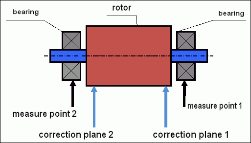
fig.5 Dynamic balancing – correction planes and measure points
Vibration sensors are installed on the bearing supports at points 1 and 2. The speed mark is fixed right on the rotor, a reflective tape is glued usually. The speed mark is used by the laser tachometer to determine the speed of the rotor and the phase of the vibration signal.
انجیر۔ 6. بیلنسیٹ-1 کا استعمال کرتے ہوئے، دو طیاروں میں توازن کے دوران سینسرز کی تنصیب
1,2-vibration sensors, 3-phase, 4- USB measuring unit, 5-laptop
In most cases, dynamic balancing is carried out by the method of three starts. This method is based on the fact that test weights of an already-known mass are installed on the rotor in series in 1 and 2 planes; so the masses and the place of installation of balancing weights are calculated based on the results of changing the vibration parameters.
وزن کی تنصیب کی جگہ کو اصلاحی طیارہ کہا جاتا ہے۔ عام طور پر، اصلاحی طیاروں کو بیئرنگ سپورٹ کے علاقے میں منتخب کیا جاتا ہے جس پر روٹر نصب ہوتا ہے۔
ابتدائی کمپن پہلے آغاز پر ماپا جاتا ہے۔ اس کے بعد، ایک معلوم ماس کا آزمائشی وزن روٹر پر ایک سپورٹ کے قریب نصب کیا جاتا ہے۔ پھر دوسرا آغاز کیا جاتا ہے، اور ہم کمپن کے پیرامیٹرز کی پیمائش کرتے ہیں، جو آزمائشی وزن کی تنصیب کی وجہ سے تبدیل ہونا چاہیے۔ پھر پہلے طیارے میں آزمائشی وزن کو ہٹا دیا جاتا ہے اور دوسرے جہاز میں نصب کیا جاتا ہے. تیسرا اسٹارٹ اپ کیا جاتا ہے اور کمپن کے پیرامیٹرز کی پیمائش کی جاتی ہے۔ جب آزمائشی وزن کو ہٹا دیا جاتا ہے، تو پروگرام خود بخود بڑے پیمانے پر اور توازن وزن کی تنصیب کے مقام (زاویوں) کا حساب لگاتا ہے۔
The point in setting up test weights is to determine how the system responds to the imbalance change. When we know the masses and the location of the sample weights, the program can calculate the so-called influence coefficients, showing how the introduction of a known imbalance affects the vibration parameters. The coefficients of influence are the characteristics of the mechanical system itself and depend on the stiffness of the supports and the mass (inertia) of the rotor-support system.
For the same type of mechanisms of the same design, the coefficients of influence will be similar. You can save them in your computer memory and use them afterwards for balancing the same type of mechanisms without carrying out test runs, which greatly improves the performance of the balancing. We should also note that the mass of test weights should be chosen as such so that the vibration parameters vary markedly when installing test weights. Otherwise, the error in calculating the coefficients of the affect increases and the quality of balancing deteriorates.
ڈیوائس بیلنسیٹ-1 کے لیے ایک گائیڈ ایک فارمولہ فراہم کرتا ہے جس کے ذریعے آپ متوازن روٹر کے کمیت اور گردش کی رفتار کے لحاظ سے، آزمائشی وزن کے وزن کا تقریباً تعین کر سکتے ہیں۔ جیسا کہ آپ تصویر 1 سے سمجھ سکتے ہیں سینٹرفیوگل قوت شعاعی سمت میں کام کرتی ہے، یعنی روٹر کے محور پر کھڑا ہے۔ اس لیے وائبریشن سینسر نصب کیے جائیں تاکہ ان کی حساسیت کا محور بھی ریڈیل سمت میں ہو۔ عام طور پر افقی سمت میں فاؤنڈیشن کی سختی کم ہوتی ہے، اس لیے افقی سمت میں کمپن زیادہ ہوتی ہے۔ لہذا، سینسر کی حساسیت کو بڑھانے کے لئے نصب کیا جانا چاہئے تاکہ ان کی حساسیت کے محور کو افقی طور پر بھی ہدایت کی جا سکے. اگرچہ کوئی بنیادی فرق نہیں ہے۔ ریڈیل سمت میں کمپن کے علاوہ، روٹر کی گردش کے محور کے ساتھ، محوری سمت میں کمپن کو کنٹرول کرنا ضروری ہے. یہ کمپن عام طور پر عدم توازن کی وجہ سے نہیں ہوتی، بلکہ دیگر وجوہات کی وجہ سے ہوتی ہے، بنیادی طور پر جوڑے کے ذریعے جڑے ہوئے شافٹوں کی غلط ترتیب اور غلط ترتیب کی وجہ سے۔ یہ کمپن توازن سے ختم نہیں ہوتی، اس صورت میں سیدھ کی ضرورت ہوتی ہے۔ عملی طور پر، عام طور پر اس طرح کے میکانزم میں روٹر کا عدم توازن اور شافٹ کی غلط ترتیب ہوتی ہے، جو کمپن کو ختم کرنے کے کام کو بہت پیچیدہ بناتا ہے۔ ایسے معاملات میں، آپ کو پہلے سیدھ میں لانا ہوگا اور پھر میکانزم کو متوازن کرنا ہوگا۔ (اگرچہ ٹارک کے مضبوط عدم توازن کے ساتھ، فاؤنڈیشن کے ڈھانچے کے "گھومنے" کی وجہ سے محوری سمت میں بھی کمپن ہوتی ہے)۔.
پیمائش کی درستگی اور خرابی کا تجزیہ
پیمائش کی درستگی کو سمجھنا پیشہ ورانہ توازن کی کارروائیوں کے لیے اہم ہے۔ Balanset-1A درج ذیل پیمائش کی درستگی فراہم کرتا ہے:
| پیرامیٹر | درستگی کا فارمولا | مثال (عام اقدار کے لیے) |
|---|---|---|
| RMS کمپن کی رفتار | ±(0.1 + 0.1×Vماپا) ملی میٹر/سیکنڈ | 5 ملی میٹر/سیکنڈ کے لیے: ±0.6 ملی میٹر/سیکنڈ 10 ملی میٹر/سیکنڈ کے لیے: ±1.1 ملی میٹر/سیکنڈ |
| گردش کی تعدد | ±(1 + 0.005×Nماپا) rpm | 1000 rpm کے لیے: ±6 rpm 3000 rpm کے لیے: ±16 rpm |
| مرحلے کی پیمائش | ±1° | تمام رفتاروں میں مستقل درستگی |
⚠️ درست توازن کے لیے اہم
- !آزمائشی وزن کی وجہ سے 20-30% طول و عرض میں تبدیلی ہونی چاہیے۔ اور/یا >20-30° مرحلے میں تبدیلی
- !اگر تبدیلیاں چھوٹی ہیں، تو پیمائش کی غلطیاں نمایاں طور پر بڑھ جاتی ہیں۔
- !کمپن طول و عرض اور مرحلے کے استحکام میں پیمائش کے درمیان 10-15% سے زیادہ فرق نہیں ہونا چاہئے
- !اگر تغیر 15% سے زیادہ ہے تو گونج کے حالات یا مکینیکل مسائل کی جانچ کریں۔
بیلنسنگ میکانزم کے معیار کا اندازہ لگانے کا معیار
Quality of rotor (mechanisms) balancing can be estimated in two ways. The first method involves comparing the value of the residual imbalance determined during the balancing with the tolerance for the residual imbalance. The specified tolerances for various classes of rotors installed in the standard ISO 1940-1-2007۔ "وائبریشن۔ سخت روٹرز کے توازن کے معیار کے تقاضے حصہ 1۔ جائز عدم توازن کا تعین"۔.
تاہم، ان رواداریوں کا نفاذ کمپن کی کم سے کم سطح کے حصول سے وابستہ میکانزم کی آپریشنل وشوسنییتا کی مکمل ضمانت نہیں دے سکتا۔ یہ اس حقیقت کی وجہ سے ہے کہ میکانزم کی وائبریشن کا تعین نہ صرف اس کے روٹر کے بقایا عدم توازن سے وابستہ قوت کی مقدار سے ہوتا ہے، بلکہ یہ متعدد دیگر پیرامیٹرز پر بھی منحصر ہوتا ہے، بشمول: میکانزم کے ساختی عناصر کی سختی K، اس کا ماس M، ڈیمپنگ گتانک، اور رفتار۔ لہذا، کچھ معاملات میں میکانزم کی متحرک خصوصیات (بشمول اس کے توازن کے معیار) کا اندازہ لگانے کے لیے، میکانزم کی بقایا کمپن کی سطح کا اندازہ لگانے کی سفارش کی جاتی ہے، جسے متعدد معیارات سے منظم کیا جاتا ہے۔
The most common standard regulating permissible vibration levels of mechanisms is آئی ایس او 10816-3:2009 پیش نظارہ مکینیکل وائبریشن - غیر گھومنے والے حصوں پر پیمائش کے ذریعے مشین کے کمپن کی تشخیص -- حصہ 3: صنعتی مشینیں جن کی برائے نام طاقت 15 کلو واٹ سے زیادہ ہے اور برائے نام رفتار 120 r/min اور 15 000 r/min کے درمیان جب سیٹو میں پیمائش کی جاتی ہے۔»
With its help, you can set the tolerance on all types of machines, taking into account the power of their electric drive.
In addition to this universal standard, there are a number of specialized standards developed for specific types of mechanisms. For example,
- آئی ایس او 14694:2003 "صنعتی پرستار - توازن کے معیار اور کمپن کی سطحوں کے لیے وضاحتیں""
- ISO 7919-1-2002 "مشینوں کا کمپن بغیر کسی حرکت کے۔ گھومنے والی شافٹ پر پیمائش اور تشخیص کے معیار۔ عمومی رہنمائی۔"
🛡️ EU کی تعمیل کے لیے اہم حفاظتی تحفظات
- !خطرے کی تشخیص کی ضرورت ہے: آپریشنز کو متوازن کرنے سے پہلے EN ISO 12100 رسک اسیسمنٹ انجام دیں۔
- !قابل عملہ: صرف تربیت یافتہ اور مصدقہ عملے کو توازن کی کارروائیاں کرنی چاہئیں
- !ذاتی حفاظتی سامان: ہمیشہ مناسب PPE فی EN 166 (آنکھوں کی حفاظت) اور EN 352 (سماعت کی حفاظت) کا استعمال کریں۔
- !ہنگامی طریقہ کار: واضح ہنگامی شٹ ڈاؤن طریقہ کار قائم کریں اور یقینی بنائیں کہ تمام آپریٹرز ان سے واقف ہیں۔
- !دستاویزی: ٹریس ایبلٹی اور تعمیل کے لیے تمام بیلنسنگ آپریشنز کے تفصیلی ریکارڈ کو برقرار رکھیں
EU کی تعمیل اور حفاظتی معلومات
مطابقت کا اعلان
Balanset-1A پورٹیبل بیلنس یورپی یونین کی درج ذیل ہدایات اور معیارات کی تعمیل کرتا ہے:
| EU ہدایت/معیاری | تعمیل کی تفصیلات | حفاظت کے تقاضے |
|---|---|---|
| مشینری کی ہدایت 2006/42/EC | مشینری اور حفاظتی اجزاء کے لیے حفاظتی تقاضے | خطرے کی تشخیص، حفاظتی ہدایات، سی ای مارکنگ |
| EMC ہدایت 2014/30/EU | برقی مقناطیسی مطابقت کی ضروریات | برقی مقناطیسی مداخلت سے استثنیٰ |
| RoHS ہدایت 2011/65/EU | خطرناک مادوں کی پابندی | لیڈ فری، مرکری فری، کیڈیمیم فری اجزاء |
| WEEE ہدایت 2012/19/EU | برقی اور الیکٹرانک آلات کو ضائع کرنا | مناسب ضائع کرنے اور ری سائیکلنگ کے طریقہ کار |
| EN ISO 12100:2010 | مشینری کی حفاظت - ڈیزائن کے عمومی اصول | خطرے کی تشخیص اور خطرے میں کمی |
| EN 60825-1:2014 | لیزر مصنوعات کی حفاظت - حصہ 1 | کلاس 2 لیزر کی حفاظت کی ضروریات |
| EN ISO 14120:2015 | گارڈز - عام ضروریات | گھومنے والی مشینری کے خطرات سے تحفظ |
الیکٹریکل سیفٹی کے معیارات
- ✓EN 61010-1: پیمائش، کنٹرول، اور لیبارٹری کے استعمال کے لیے برقی آلات کے لیے حفاظتی تقاضے
- ✓EN 60950-1: انفارمیشن ٹیکنالوجی کے سامان کی حفاظت (USB سے چلنے والا آلہ)
- ✓IEC 61000 سیریز: برقی مقناطیسی مطابقت کے معیارات
- ✓آپریٹنگ وولٹیج: 5V DC بذریعہ USB (اضافی کم وولٹیج)
- ✓بجلی کی کھپت: <2.5W
- ✓تحفظ کی کلاس: IP20 (اندرونی استعمال کے لیے)
گھومنے والے سامان کی حفاظت
⚠️ لازمی حفاظتی طریقہ کار (EN ISO 12100)
انتباہ: گھومنے والی مشینری کے ساتھ کام کرتے وقت، درج ذیل حفاظتی تقاضوں پر عمل کریں:
- !EN ISO 14118: غیر متوقع آغاز کی روک تھام - سینسر کی تنصیب سے پہلے لاک آؤٹ/ٹیگ آؤٹ طریقہ کار استعمال کریں۔
- !EN ISO 14120: اس بات کو یقینی بنائیں کہ گھومنے والے تمام آلات کی حفاظت کی جاتی ہے۔
- !EN ISO 13857: گھومنے والے حصوں سے کم از کم محفوظ فاصلہ برقرار رکھیں (جسم کے لیے 500 ملی میٹر، انگلیوں کے لیے 120 ملی میٹر)
- !ذاتی حفاظتی سامان: حفاظتی شیشے فی EN 166 پہنیں، EN 352 کے مطابق سماعت کا تحفظ، اور ڈھیلے لباس سے پرہیز کریں۔
- !حرکت میں رہتے ہوئے گھومنے والی مشینری پر کبھی بھی سینسر یا آزمائشی وزن نہ لگائیں۔
- !اس بات کو یقینی بنائیں کہ سینسر کی تنصیب سے پہلے مشین مکمل طور پر بند اور محفوظ ہے۔
- !ایمرجنسی اسٹاپ: آپریٹر پوزیشن کے 3 میٹر کے اندر قابل رسائی ہونا ضروری ہے۔
- !صرف اہل اور تصدیق شدہ اہلکار ہی توازن کے کام انجام دیں۔
لیزر سیفٹی کی درجہ بندی
🔴 کلاس 2 لیزر ڈیوائس (EN 60825-1:2014)
- طول موج: 650 nm (سرخ نظر آنے والی روشنی)
- زیادہ سے زیادہ آؤٹ پٹ پاور: <1 میگاواٹ
- بیم قطر: 100 ملی میٹر کے فاصلے پر 3-5 ملی میٹر
- اختلاف: <1.5 mrad
- حفاظت کی درجہ بندی: آنکھ لمحاتی نمائش کے لیے محفوظ (<0.25 سیکنڈ)
- مطلوبہ لیبلنگ: ""لیزر ریڈی ایشن - بیم میں نہ گھوریں - کلاس 2 لیزر پروڈکٹ""
- کلاس تک رسائی: غیر محدود (عام رسائی کی اجازت ہے)
لیزر سیفٹی کے طریقہ کار:
- کبھی بھی جان بوجھ کر لیزر بیم کو نہ دیکھیں
- افراد، گاڑیوں یا ہوائی جہاز کو لیزر کا نشانہ نہ بنائیں
- آپٹیکل آلات (دوربین، دوربین) کے ساتھ لیزر بیم دیکھنے سے گریز کریں۔
- چمکدار سطحوں سے مخصوص عکاسی سے آگاہ رہیں
- استعمال میں نہ ہونے پر لیزر کو بند کر دیں۔
- کسی بھی آنکھ کی نمائش کے واقعات کی فوری طور پر اطلاع دیں۔
- توسیعی نمائش کے لیے لیزر حفاظتی شیشے (OD 2+ 650nm) استعمال کریں۔
پیمائش کی درستگی اور انشانکن
| پیرامیٹر | درستگی | انشانکن تعدد |
|---|---|---|
| کمپن کا طول و عرض | پڑھنے کا ±5% | سالانہ یا 1000 گھنٹے کے بعد |
| مرحلے کی پیمائش | ±1° | سالانہ |
| گردش کی رفتار | پڑھنے کا ±0.1% | سالانہ |
| سینسر کی حساسیت | 13 mV/(mm/s) ±10% | سینسر کو تبدیل کرتے وقت |
ماحولیاتی تعمیل
- ✓آپریٹنگ ماحول: 5°C سے 50°C، < 85% RH نان کنڈینسنگ
- ✓ذخیرہ کرنے کا ماحول: -20 ° C سے 70 ° C، <95% RH نان کنڈینسنگ
- ✓اونچائی: سطح سمندر سے 2000 میٹر تک
- ✓کمپن مزاحمت: IEC 60068-2-6 (10-500 ہرٹز، 2 جی ایکسلریشن)
- ✓جھٹکا مزاحمت: IEC 60068-2-27 (15 گرام، 11 ملی میٹر دورانیہ)
- ✓آئی پی کی درجہ بندی: IP20 (ٹھوس اشیاء کے خلاف تحفظ> 12 ملی میٹر)
آپریشن کے تقاضے
- ✓آپریٹرز کو EU کے معیار کے مطابق مشینری کی حفاظت میں تربیت دی جانی چاہیے۔
- ✓استعمال سے پہلے EN ISO 12100 کے مطابق خطرے کی تشخیص درکار ہے۔
- ✓مینوفیکچرر کی وضاحتوں کے مطابق سامان کو برقرار رکھیں
- ✓کسی بھی حفاظتی واقعات یا سامان کی خرابی کی فوری طور پر اطلاع دیں۔
- ✓ٹریس ایبلٹی کے لیے تمام بیلنسنگ آپریشنز کا تفصیلی ریکارڈ رکھیں
دستاویزات کے تقاضے
EU کی تعمیل کے لیے، درج ذیل دستاویزات کو برقرار رکھیں:
- ✓EN ISO 12100 کے مطابق خطرے کی تشخیص کی دستاویزات
- ✓آپریٹر کی تربیت کے ریکارڈ اور سرٹیفیکیشن
- ✓آلات کیلیبریشن اور دیکھ بھال کے لاگز
- ✓تاریخوں، آپریٹرز اور نتائج کے ساتھ آپریشن کے ریکارڈ کو متوازن کرنا
- ✓حفاظتی واقعات کی رپورٹس اور اصلاحی اقدامات
- ✓آلات میں ترمیم یا مرمت کی دستاویزات
ٹیکنیکل سپورٹ اور سروس
تکنیکی مدد، انشانکن خدمات، اور اسپیئر پارٹس کے لیے:
- ✓مینوفیکچرر: Vibromera
- ✓مقام: Rua Alcaide de Faria 193، پورٹو، پرتگال
- ✓ویب سائٹ: https://vibromera.eu
- ✓معاون زبانیں: تمام بڑی زبانیں۔ متن پر مبنی مواصلت دستیاب ہے۔.
- ✓سروس کوریج: دنیا بھر میں شپنگ دستیاب ہے۔
- ✓وارنٹی: خریداری کی تاریخ سے 24 ماہ
- ✓انشانکن سروس: مجاز سروس سینٹرز کے ذریعے دستیاب ہے۔
