
Portativ balanslaşdırıcı ""BALANSET-1A""
İki Kanallı PC Əsaslı Dinamik Balanslama Sistemi
İstismar Təlimatı
yenilənmiş 1.56 May 2023
2023 | Estoniya, Narva
TƏHLÜKƏSİZLİK BİLDİRİMİ: Bu cihaz Aİ təhlükəsizlik standartlarına uyğundur. Sinif 2 Lazer Məhsulu. Fırlanan avadanlıqların təhlükəsizlik prosedurlarına əməl edin. Aşağıda tam təhlükəsizlik məlumatlarına baxın →
1. BALANSLAŞMA SİSTEMİNƏ İCLAMA
Balanset-1A balancer ventilyatorlar, daşlama çarxları, millər, qırıcılar, nasoslar və digər fırlanan maşınlar üçün tək və iki müstəvili dinamik balanslaşdırma xidmətləri göstərir.
Balanset-1A balanslaşdırıcısı iki vibrosensor (akselerometr), lazer faza sensoru (taxometr), əvvəlcədən gücləndiricilər, inteqratorlar və ADC əldə etmə modulu olan 2 kanallı USB interfeys bloku və Windows əsaslı balanslaşdırma proqram təminatından ibarətdir. Balanset-1A üçün noutbuk və ya digər Windows (WinXP...Win11, 32 və ya 64bit) ilə uyğun kompüter tələb olunur.
Balanslama proqramı tək-səviyyəli və iki-səviyyəli balanslamada düzgün balanslama həllini avtomatik olaraq təmin edir. Balanset-1A Vibrasiya üzrə mütəxəssis olmayanlar üçün istifadəsi sadədir.
Bütün balanslaşdırma nəticələri arxivdə saxlanılıb və hesabatlar yaratmaq üçün istifadə oluna bilər.
Əsas Xüsusiyyətlər
İstifadəsi asandır
- • İstifadəçi tərəfindən seçilə bilən sınaq kütləsi
- • Sınaq kütləsinin etibarlılıq pop-upı
- • Əl ilə məlumatların daxil edilməsi
Ölçmə Qabiliyyətləri
- • RPM, amplituda və faza
- • FFT spektr analizi
- • Dalğa forması və spektr ekranı
- • İki kanallı eyni vaxtda verilənlər
Qabaqcıl Funksiyalar
- • Saxlanılan təsir əmsalları
- • Təmir balanslaşdırması
- • Mandrel eksantrikliyi hesablanması.
- • ISO 1940 tolerantlıq kalkulyatoru.
Məlumatların idarə edilməsi
- • Limitsiz balanslaşdırılmış məlumat saxlama
- • Vibrasiya dalğa formasının saxlanması
- • Arxiv və hesabatlar
Hesablama Alətləri
- • Bölünmüş çəki hesablanması
- • Qazma hesablanması
- • Korreksiya müstəvilərinin dəyişdirilməsi
- • Qütb qrafikinin vizuallaşdırılması
Təhlil Seçimləri
- • Sınaq çəkilərini çıxarın və ya saxlayın
- • RunDown diaqramları (eksperimental)
2. TƏYİNAT
| Parametr | Spesifikasiya |
|---|---|
| Vibrasiya sürətinin orta kvadrat kök (RMS) dəyərinin ölçü diapazonu, mm/s (1x vibrasiya üçün) | 0,2-dən 80-ə qədər |
| Vibrasiya sürətinin RMS ölçüsünün tezlik diapazonu, Hz | from 5 to 1000 (amplitude error ≤10% from 5 to 550 Hz; up to 20% from 550 to 1000 Hz) |
| Düzəliş müstəvilərinin sayı | 1 və ya 2 |
| Dönmə tezliyinin ölçülmə diapazonu, rpm | 250 – 90000 |
| Vibrasiya fazasının ölçülmə diapazonu, bucaq dərəcələri | 0-dan 360-a |
| Vibrasiya fazasının ölçülmə xətası, bucaq dərəcələri | ± 1 |
| RMS vibrasiya sürətinin ölçü dəqiqliyi | ±(0,1 + 0,1×Völçülür) mm/san |
| Fırlanma tezliyinin ölçü dəqiqliyi | ±(1 + 0,005×Nölçülür) rpm |
| Arızalar arasında orta vaxt (MTBF), saat, dəq | 1000 |
| Orta xidmət müddəti, illər, min | 6 |
| Ölçülər (çətin halda), sm | 39*33*13 |
| Kütlə, kq | Beşdən az |
| Vibrator sensorunun ümumi ölçüləri, mm, maks | 25*25*20 |
| Vibrator sensorunun kütləsi, kq, maks | 0.04 |
|
Əməliyyat şərtləri: - Temperatur diapazonu: 5°C-dən 50°C-yə qədər - Nisbi rütubət: < 85%, doymamış - Güclü elektrik-maqnit sahəsi və güclü təsir olmadan |
|
3. QUTU
Balanset-1A balanslaşdırıcısına iki tək oxlu akselerometr, lazer faza istinad markeri (rəqəmsal taxometr), qabaqlayıcı gücləndiricilər, inteqratorlar və ADC toplama modulu ilə 2 kanallı USB interfeys bloku və Windows əsaslı balanslaşdırma proqramı daxildir.
Çatdırılma Dəsti
| Təsvir | Sayı | Qeyd |
|---|---|---|
| USB interfeys vahidi | 1 | |
| Lazer faza istinad işarəsi (tachometr) | 1 | |
| Tək oxlu akselerometrlər | 2 | |
| maqnit stend | 1 | |
| Rəqəmsal tərəzilər | 1 | |
| Nəqliyyat üçün sərt çanta | 1 | |
| ""Balanset-1A". İstifadəçi təlimatı. | 1 | |
| Balanslaşdırma proqramı olan fleş disk | 1 |
4. BALANS PRİNSİPLƏRİ
4.1. ""Balanset-1A" (şəkil 4.1) USB interfeys blokunu ehtiva edir (1), iki akselerometr (2) and (3), faza istinad işarəsi (4) və portativ kompüter (təchiz olunmur) (5).
Çatdırılma dəstinə maqnit stend də daxildir (6) faza istinad markerinin və rəqəmsal tərəzilərin quraşdırılması üçün istifadə olunur 7.
X1 və X2 konnektorları müvafiq olaraq vibrasiya sensorlarının 1-ci və 2-ci ölçmə kanallarına qoşulması üçün nəzərdə tutulub, X3 konnektoru isə faz istinad markerinin qoşulması üçün istifadə olunur.
USB kabeli enerji təchizatı və USB interfeys vahidinin kompüterə qoşulmasını təmin edir.

Şəkil 4.1. "Balanset-1A"-nın çatdırılma dəsti"
Mexanik vibrasiyalar vibrasiya sensorunun çıxışında vibrasiya sürətlənməsinə mütənasib elektrik siqnalına səbəb olur. ADC modulundan rəqəmləşdirilmiş siqnallar USB vasitəsilə portativ kompüterə ötürülür (5). Faza istinad markeri fırlanma tezliyini və vibrasiya faza bucağını hesablamaq üçün istifadə edilən nəbz siqnalını yaradır. Windows əsaslı proqram təminatı tək və iki müstəvi balanslaşdırma, spektr analizi, qrafiklər, hesabatlar, təsir əmsallarının saxlanması üçün həllər təqdim edir.
5. Təhlükəsizlik tədbirləri
⚡ DİQQƏT - Elektrik Təhlükəsizliyi
5.1. 220 V-da işləyərkən elektrik təhlükəsizlik qaydalarına riayət edilməlidir. Cihaz 220 V-a qoşulduqda onu təmir etmək qadağandır.
5.2. Cihazı aşağı keyfiyyətli AC enerji mühitində və ya şəbəkə müdaxiləsi olduqda istifadə edirsinizsə, kompüterin batareya blokundan müstəqil enerji mənbəyindən istifadə etməyiniz tövsiyə olunur.
⚠️ Dönən Avadanlıqlar üçün Əlavə Təhlükəsizlik Tələbləri
- !Maşın kilidi: Sensorları quraşdırmadan əvvəl həmişə düzgün kilidləmə/etiketləmə prosedurlarını həyata keçirin
- !Fərdi Qoruyucu Avadanlıqlar: Qoruyucu eynəklər, eşitmə qoruyucuları taxın və fırlanan maşınların yanında boş paltarlardan qaçın
- !Təhlükəsiz Quraşdırma: Bütün sensorların və kabellərin etibarlı şəkildə bağlandığından və fırlanan hissələrə tutulmadığından əmin olun
- !Fövqəladə Prosedurlar: Fövqəladə dayanacaqların yerini və söndürmə prosedurlarını bilin
- !Təlim: Yalnız təlim keçmiş işçilər fırlanan maşınlarda balanslaşdırma avadanlığını idarə etməlidirlər
6. PROQRAM VƏ APARAT PARAMETLƏRİ
6.1. USB sürücülərinin və balanslaşdırma proqram təminatının quraşdırılması
İşə başlamazdan əvvəl sürücüləri və balanslaşdırma proqramını quraşdırın.
Qovluqların və faylların siyahısı
Quraşdırma diski (flash sürücü) aşağıdakı faylları və qovluqları ehtiva edir:
- Bs1Av###Quraşdırma – "Balanset-1A" balanslaşdırma proqramı olan qovluq (### – versiya nömrəsi)
- ArdDrv - USB sürücüləri
- EBalancer_qayde kitabcası.pdf - bu təlimat
- Bal1Av###Quraşdırma.exe – quraşdırma faylı. Bu fayl yuxarıda qeyd olunan bütün arxivləşdirilmiş faylları və qovluqları ehtiva edir. ### – "Balanset-1A" proqram təminatının versiyası.
- Ebalanc.cfg - həssaslıq dəyəri
- Bal.ini – bəzi başlanğıc məlumatları
Proqram təminatının quraşdırılması proseduru
Sürücüləri və ixtisaslaşmış proqram təminatını quraşdırmaq üçün faylı işə salın Bal1Av###Quraşdırma.exe və düymələri basaraq quraşdırma təlimatlarını izləyinSonrakı», «OKvə s.
Quraşdırma qovluğunu seçin. Adətən verilən qovluq dəyişdirilməməlidir.
Sonra proqram Proqram qrupu və masaüstü qovluqlarını göstərməyi tələb edir. Düşərgə düyməsini basın. Sonrakı.
Quraşdırmanın tamamlanması
- ✓Müayinə olunmuş və ya balanslaşdırılmış mexanizmə sensorları quraşdırın (Sensorların necə quraşdırılması barədə ətraflı məlumat Əlavə 1-də verilib)
- ✓Vibrasiya sensorlarını 2 və 3-ü X1 və X2 girişlərinə, faz bucağı sensorunu isə USB interfeys vahidinin X3 girişinə qoşun.
- ✓USB interfeys vahidini kompüterin USB-portuna qoşun.
- ✓AC enerji təchizatı istifadə edərkən kompüteri elektrik şəbəkəsinə qoşun. Enerji təchizatını 220 V, 50 Hz-ə qoşun.
- ✓Masaüstündə "Balanset-1A" qısa yolunu vurun.
7. BALANSLAŞMA PROQRAMI
7.1. Ümumi
İlkin Pəncərə
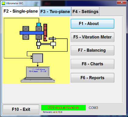
"Balanset-1A" proqramını işə saldıqda Şəkil 7.1-də göstərilən İlkin pəncərə görünür.

Şəkil 7.1. "Balanset-1A"-nın ilkin pəncərəsi"
İlkin pəncərədə üzərinə kliklədikdə həyata keçirilən funksiyaların adları ilə 9 düymə var.
F1-«Haqqında»
Şəkil 7.2. F1 - "Haqqında" pəncərəsi
F2-«Tək müstəvi», F3-«İki müstəvi»
Basmaq ""F2- Tək təyyarə""(və ya F2 kompüter klaviaturasındakı funksiya düyməsi) kanalda ölçmə vibrasiyasını seçir X1.
Bu düyməni kliklədikdən sonra Şəkil 7.1-də göstərilən kompüter ekran diaqramı yalnız birinci ölçü kanalında (və ya tək müstəvidə balanslaşdırma prosesində) vibrasiyanın ölçülməsi prosesini təsvir edir.
"düyməsinə basmaq"F3-İki təyyarəli""(və ya F3 Kompüter klaviaturasında funksiya düyməsi iki kanalda vibrasiya ölçmələrinin rejimini seçir. X1 and X2 eyni zamanda. (Şək. 7.3.)
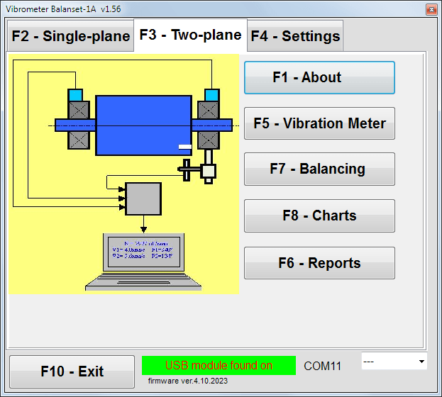
Şəkil 7.3. "Balans dəsti-1A"-nın ilkin pəncərəsi. İki müstəvi balanslaşdırma.
F4 - "Parametrlər"
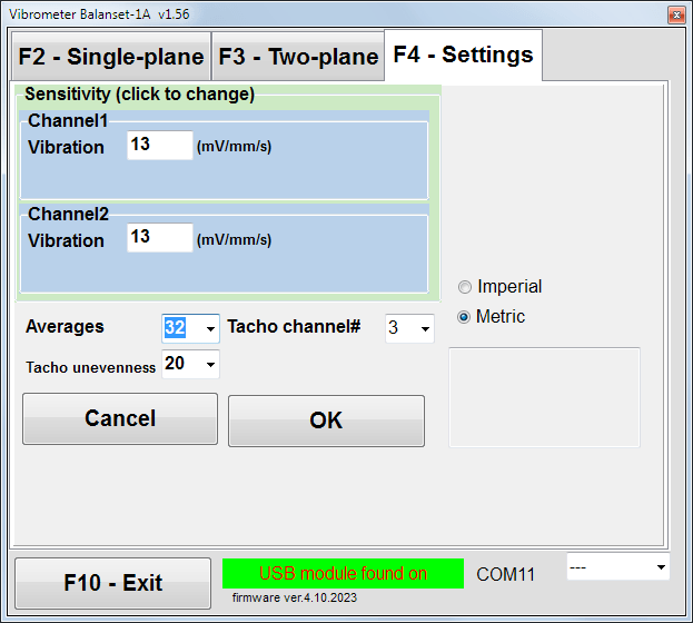
Şəkil 7.4. "Parametrlər" pəncərəsi
Bu pəncərədə bəzi Balanset-1A parametrlərini dəyişə bilərsiniz.
- həssaslıqNominal dəyər 13 mV/mm/s-dir.
Sensorların həssaslıq əmsallarını dəyişmək yalnız sensorları əvəz edərkən tələb olunur!
Diqqət!
Həssaslıq əmsalını daxil etdikdə, onun kəsr hissəsi tam ədəd hissəsindən onluq nöqtə ilə ayrılır ("," işarəsi).
- Orta hesablama - ortalama sayı (daha dəqiqliklə məlumatların ortalaması aparılan rotorun dövrə sayı)
- Tacho kanalı# - Tacho qoşuludur kanal#. Varsayılan olaraq - 3-cü kanal.
- Nəhənglik - yuxarıda göstərilən xəbərdarlıq verən bitişik taxo impulsları arasındakı müddət fərqi ""Tachometrın nasazlığı"
- İmperial/Metrik - Vahidlər sistemini seçin.
COM port nömrəsi avtomatik təyin olunur.
F5 - "Vibrasiya ölçən"
Bu düyməni basmaq (və ya funksiya düyməsini F5 kompüter klaviaturasında) düymələrin vəziyyətindən asılı olaraq virtual Vibrasiyaölçən cihazının bir və ya iki ölçmə kanalında vibrasiya ölçmə rejimini aktivləşdirir."F2-tək müstəvili", ""F3-iki müstəvili".
F6 - "Hesabatlar"
Bu düyməni basmaqla (və ya F6 Kompüter klaviaturasında funksiya düyməsi balanslaşdırma Arxivini işə salır, buradan müəyyən mexanizm (rotor) üçün balanslaşdırmanın nəticələrini əks etdirən hesabatı çap edə bilərsiniz.
F7 – «Balanslaşdırma»
Bu düyməni (və ya klaviaturanızdakı F7 funksiya düyməsini) basmaq, hansı ölçmə rejiminin seçilməsindən asılı olaraq bir və ya iki düzəliş müstəvisində balanslaşdırma rejimini aktivləşdirir."F2-tək müstəvili", ""F3-iki müstəvili".
F8 – «Qrafiklər»
Bu düyməni basmaqla (və ya F8 kompüter klaviaturasındakı funksiya düyməsi) qrafik Vibrasiyaölçənini aktivləşdirir, onun tətbiqi zamanı displeydə zaman funksiyasının vibrasiya qrafiklərinin amplitudası və fazasının rəqəmsal dəyərləri ilə eyni vaxtda göstərilir.
F10 - "Çıxış"
Bu düyməni basmaqla (və ya F10 kompüter klaviaturasındakı funksiya düyməsi) "Balanset-1A" proqramını tamamlayır.
7.2. "Vibrasiya ölçən cihaz""
İşləməzdən əvvəl ""Vibrasiya ölçən""rejimində vibrasiya sensorlarını cihaza quraşdırın və onları müvafiq olaraq USB interfeys blokunun X1 və X2 konnektorlarına qoşun. Taxometr USB interfeys blokunun X3 girişinə qoşulmalıdır.

Şəkil 7.5 USB interfeys bloku
Taxo ilə işləmək üçün rotorun səthinə əks etdirici lent qoyun.
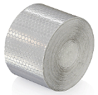
Şəkil 7.6. Yansıtıcı lent.
Sensorların quraşdırılması və konfiqurasiyası üçün tövsiyələr Əlavə 1-də verilib.
Vibrasiya ölçən rejimində ölçməyə başlamaq üçün "düyməsini basın"F5 – Titrəmə ölçən""proqramın İlkin pəncərəsində (şəkil 7.1-ə baxın).
Vibrasiya ölçən Pəncərə görünür (bax. Şək. 7.7)

Şəkil 7.7. Titrəməölçən rejimi. Dalğa və Spektr.
Titrəmə ölçmələrinə başlamaq üçün "düyməsini basın"F9 - Çalışın"" (və ya funksiya düyməsini basın F9 klaviaturada
If Tətik rejimi Avtomatik yoxlanılır - vibrasiya ölçmələrinin nəticələri vaxtaşırı ekranda göstəriləcək.
Birinci və ikinci kanallarda vibrasiyanın eyni vaxtda ölçülməsi halında, " sözlərinin altında yerləşən pəncərələr"Təyyarə 1""və""Təyyarə 2""doldurulacaq.
"Vibrasiya" rejimində vibrasiyanın ölçülməsi həmçinin faza bucağı sensoru kəsildikdə də həyata keçirilə bilər. Proqramın Başlanğıc pəncərəsində ümumi RMS vibrasiyasının dəyəri (V1-lər, V2-lər) yalnız göstəriləcək.
Vibrasiya ölçmə rejimində növbəti parametrlər var
- RMS Aşağı, Hz – ümumi vibrasiyanın RMS hesablanması üçün ən aşağı tezlik
- Bant genişliyi - qrafikdə vibrasiya tezliyi bant genişliyi
- Orta dəyərlər - daha çox ölçmə dəqiqliyi üçün orta rəqəm
"Vibrasiya ölçən" rejimində işi başa çatdırmaq üçün "düyməsini basın"F10 – Çıxış""və İlkin pəncərəyə qayıdın.

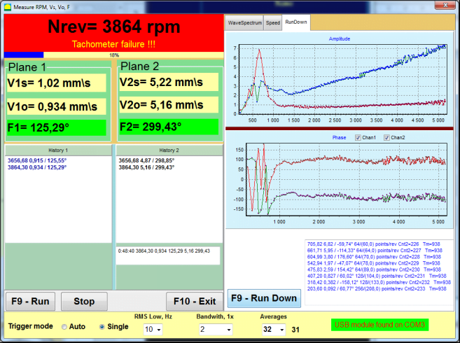
Şəkil 7.8. Titrəməölçən rejimi. Dönmə sürətinin dengesizliyı, 1x titrəmə dalğa forması.
Şəkil 7.9. Titrəməölçən rejimi. Boşda işləmə (Beta versiyası, zəmanət yoxdur!).
7.3 Balanslaşdırma proseduru
Balanslaşdırma yaxşı texniki vəziyyətdə və düzgün quraşdırılmış mexanizmlər üçün həyata keçirilir. Əks halda, balanslaşdırmadan əvvəl mexanizm təmir edilməli, uyğun rulmanlara yerləşdirilməli və möhkəmləndirilməlidir. Rotor balanslaşdırma prosesinə mane ola biləcək çirklərdən təmizlənməlidir.
Balanslamadan əvvəl Vibrasiyaölçən rejimində (F5 düyməsi) ölçmə apararaq vibrasiyanın əsasən 1x vibrasiya olduğunu təsdiqləyin.
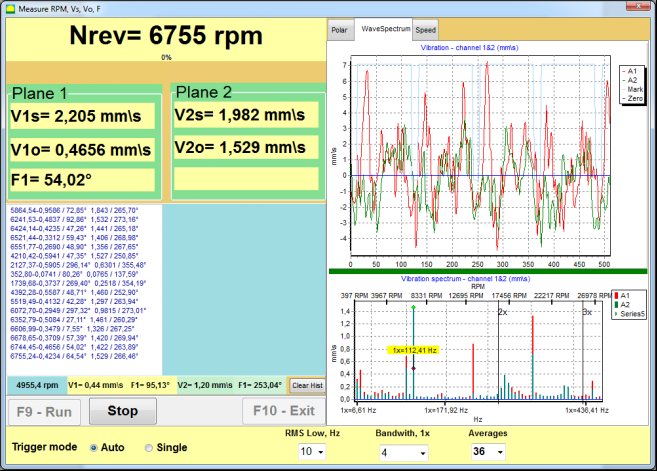
Şəkil 7.10. Titrəməölçən rejimi. Ümumi (V1s, V2s) və 1x (V1o, V2o) titrəməni yoxlama.
Ümumi vibrasiya V1s (V2s) dəyəri təxminən fırlanma tezliyində (1x vibrasiya) V1o (V2o) titrəyişinin böyüklüyünə bərabərdirsə, vibrasiya mexanizminə əsas töhfənin rotorun balanssızlığından gəldiyini güman etmək olar. Ümumi vibrasiya V1s (V2s) dəyəri 1x vibrasiya komponenti V1o (V2o) ilə müqayisədə xeyli yüksəkdirsə, mexanizmin vəziyyətini yoxlamaq tövsiyə olunur - podşipniklərin vəziyyətini, onun bazaya bərkidilməsini, fırlanma zamanı sabit hissələrlə rotor arasında əlaqənin olmaması və s.
Vibrasiya ölçmə cihazı rejimində ölçülmüş dəyərlərin sabitliyinə də diqqət yetirməlisiniz – ölçmə prosesində titrəyişin amplitudası və fazası 10-15%-dən çox dəyişməməlidir. Əks halda, mexanizmin rezonansa yaxın bölgədə işlədiyini güman etmək olar. Bu halda, rotorun fırlanma sürətini dəyişdirin və bu mümkün deyilsə - maşının təməl üzərində quraşdırılması şərtlərini dəyişdirin (məsələn, müvəqqəti olaraq yay dayaqlarına quraşdırın).
Rotorun balanslaşdırılması üçün təsir əmsalı üsulu balanslaşdırmadan (3-çalışma üsulu) istifadə edilməlidir.
Sınaq işləri sınaq kütləsinin vibrasiya dəyişməsinə, düzəldici kütlələrin kütləsinə və yerləşdirilmə yerinə (bucağa) təsirini müəyyən etmək üçün aparılır.
Əvvəlcə mexanizmin ilkin titrəməsini müəyyən edin (birinci cəhddə ağırlıq olmadan başlayın), sonra sınaq ağırlığını birinci müstəvidə yerləşdirib ikinci cəhdə başlayın. Sonra sınaq ağırlığını birinci müstəvidən çıxarıb ikinci müstəvidə yerləşdirin və ikinci cəhdə başlayın.
Sonra proqram korreksiya ağırlıqlarının quraşdırılma çəkisini və yerləşmə bucağını hesablayır və ekranda göstərir.
Tək müstəvidə (statik) balanslaşdırma zamanı ikinci işə salınma tələb olunmur.
Sınaq çəkisi rotor üzərində münasib bir yerə təsadüfi qaydada qoyulur, sonra real radius konfiqurasiya proqramına daxil edilir.
(Pozisiya radiusu yalnız qram-millimetrlə ifadə olunan balanssızlıq miqdarını hesablamaq üçün istifadə olunur)
Vacibdir!
- Ölçmələr mexanizmin sabit fırlanma sürəti ilə aparılmalıdır!
- Düzəliş ağırlıqları sınaq ağırlıqları ilə eyni radiusda quraşdırılmalıdır!
Sınaq çəkisinin kütləsi elə seçilir ki, onun quraşdırma mərhələsindən (> 20-30°) və (20-30%) sonra vibrasiyanın amplitudası əhəmiyyətli dərəcədə dəyişsin. Dəyişikliklər çox kiçik olarsa, sonrakı hesablamalarda səhv çox artır. Rahatlıqla sınaq kütləsini faza işarəsi ilə eyni yerdə (eyni bucaqda) təyin edin.
Sınaq Çəki Kütləvi Hesablama Formulu
Mt = Cənab × Ksupport × Kvibrasiya / (Rt × (N/100)²)
Harada:
- Mt - sınaq çəkisi kütləsi, g
- cənab - rotor kütləsi, q
- Kdəstək - dəstək sərtlik əmsalı (1-5)
- Kvibrasiya - vibrasiya səviyyəsi əmsalı (0.5-2.5)
- Rt - sınaq çəkisi quraşdırma radiusu, sm
- N - rotor sürəti, rpm
Dəstək sərtlik əmsalı (Ksupport):
- 1.0 - Çox yumşaq dayaqlar (rezin amortizatorlar)
- 2.0-3.0 - Orta sərtlik (standart podşipniklər)
- 4.0-5.0 - Sərt dayaqlar (kütləvi təməl)
Vibrasiya səviyyəsi əmsalı (Kvibrasiya):
- 0.5 - Aşağı vibrasiya (5 mm/san-ə qədər)
- 1.0 - Normal vibrasiya (5-10 mm/san)
- 1.5 - Yüksək vibrasiya (10-20 mm/san)
- 2.0 - Yüksək vibrasiya (20-40 mm/san)
- 2.5 - Çox yüksək vibrasiya (>40 mm/san)
🔗 Onlayn kalkulyatorumuzdan istifadə edin:
Sınaq Çəki Kalkulyatoru →⚠️ Vacibdir!
Hər test qaçışıdan sonra sınaq kütləsi çıxarılır! Düzəliş çəkiləri sınaq çəkisinin quraşdırıldığı yerin koordinatlarından hesablanmış bucaq altında yerləşdirilir. Rotorun fırlanma istiqamətinə doğru!
Bucaq Hesablamasının İzahı:
Düzəliş çəkisinin quraşdırma bucağıdır HƏMİŞƏ sınaq çəkisinin quraşdırma nöqtəsindən rotorun fırlanma istiqamətində sayılır.
- Sıfır Nöqtəsi (0°): Sınaq çəkisini quraşdırdığınız dəqiq yer istinad nöqtəniz olur (0 dərəcə).
- İstiqamət: Rotorun fırlandığı istiqamətdə bucağı ölçün.
Misal: Əgər rotor saat əqrəbi istiqamətində fırlanırsa, sınaq çəkisi mövqeyindən bucağı saat əqrəbi istiqamətində ölçün. - Şərh: Əgər proqram bir bucaq göstərirsə 120°, düzəliş çəkisini quraşdırmalısınız 120 dərəcə irəlidə sınaq çəkisinin fırlanma istiqamətindəki mövqeyi.
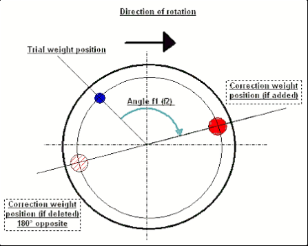
Şək. 7.11. Düzəliş çəkisinin quraşdırılması.
Tövsiyə olunur!
Dinamik balanslaşdırmadan əvvəl statik balanssızlığın çox yüksək olmadığından əmin olmaq tövsiyə olunur. Üfüqi oxu olan rotorlar üçün rotor cari vəziyyətdən 90 dərəcə bucaqla əl ilə fırlana bilər. Rotor statik balanssızdırsa, tarazlıq vəziyyətinə dönəcəkdir. Rotor tarazlıq vəziyyətini qəbul etdikdən sonra, tarazlayıcı çəki rotor uzunluğunun təxminən orta hissəsində yuxarı nöqtədə quraşdırmaq lazımdır. Ağırlıq elə seçilməlidir ki, rotor heç bir vəziyyətdə hərəkət etməsin.
Bu cür əvvəlcədən balanslaşdırma güclü balanssız rotorun ilk başlanğıcında vibrasiya miqdarını azaldacaq.
Sensorun quraşdırılması və quraşdırılması
VTitrəmə sensoru maşında seçilmiş ölçmə nöqtəsində quraşdırılmalı və USB interfeys blokunun X1 girişinə qoşulmalıdır.
İki montaj konfiqurasiyası var:
- Maqnitlər
- Yivli şpilkalar M4
Optik tacho sensoru USB interfeys vahidinin X3 girişinə qoşulmalıdır. Bundan əlavə, bu sensordan istifadə etmək üçün rotor səthinə xüsusi əks etdirici işarə vurulmalıdır.
📏 Optik Sensor Quraşdırma Tələbləri
- ✓Rotor səthinə olan məsafə: 50-500 mm (sensor modelindən asılı olaraq)
- ✓Yansıtıcı lent eni: Minimum 1-1,5 sm (sürət və radiusdan asılıdır)
- ✓Orientasiya: Rotor səthinə perpendikulyar
- ✓Montaj: Sabit yerləşdirmə üçün maqnit dayaq və ya sıxacdan istifadə edin
- ✓Birbaşa günəş işığından çəkinin və ya sensor/lentdə parlaq süni işıqlandırma
💡 Bant eninin hesablanması: Optimal performans üçün lent enini hesablayın:
L ≥ (N × R)/30000 ≥ 1,0-1,5 sm
Burada: L - lent eni (sm), N - rotor sürəti (rpm), R - lent radiusu (sm)
Sensorların yerləşdirilməsi və balanslaşdırma zamanı obyektə bərkidilməsi ilə bağlı ətraflı tələblər 1-ci əlavədə göstərilmişdir.
7.4 Tək müstəvi balanslaşdırma
Şəkil 7.12. "Tək təyyarə balansı"
Balanslaşdırma arxivi
Proqram üzərində işə başlamaq üçün ""Tək müstəvi balanslaşdırma""rejimində" düyməsini basın"F2-Tək-səviyyəli"" düyməsini basın (və ya kompüter klaviaturasındakı F2 düyməsini basın).
Sonra "düyməsinə basın"F7 – Balanslama"" düyməsinə, bundan sonra Tək müstəvi balanslaşdırma arxivi Pəncərə görünəcək, balanslaşdırma məlumatları orada yadda saxlanılacaq (bax Şəkil 7.13).

Şəkil 7.13 Tək planda balanslaşdırma arxivinin seçilməsi pəncərəsi.
Bu pəncərədə rotorun adı barədə məlumatları daxil etməlisiniz (Rotor adı), rotorun quraşdırıldığı yer (Yerləşdirin), titrəmə və qalıq balanssızlıq üçün dözümlüklər (Dözümlülük), ölçmə tarixi. Bu məlumatlar verilənlər bazasında saxlanılır. Həmçinin Arc### adlı qovluq yaradılır; burada ### diaqramların, hesabat faylının və s. saxlanacağı arxiv nömrəsidir. Balanslaşdırma tamamlandıqdan sonra daxili redaktorda redaktə və çap edilə bilən hesabat faylı yaradılır.
Lazımi məlumatları daxil etdikdən sonra "düyməsini basmalısınız"F10-OK"" düyməsinə, sonra isə ""Tək müstəvi balanslaşdırma"" pəncərə açılacaq (Şəkil 7.13-ə baxın)
Balanslaşdırma parametrləri (1 müstəvi)

Şəkil 7.14. Tək müstəvi. Tarazlama parametrləri
Bu pəncərənin sol tərəfində vibrasiya ölçmələrinin məlumatları və ölçmə idarəetmə düymələri göstərilir ""Qaçış # 0", "Qaçış # 1", "Yürüyüşü tənzimlə".
Bu pəncərənin sağ tərəfində üç nişan var:
- Balanslaşdırma parametrləri
- Qrafiklər
- nəticə
""Balanslaşdırma parametrləri""tab balans parametrlərini daxil etmək üçün istifadə olunur:
- ""Təsir əmsalı"" -
- "Yeni rotor""- saxlanılan balanslaşdırma əmsalları olmayan və korreksiya çəkisinin kütləsini və quraşdırma bucağını təyin etmək üçün iki dəfə hərəkət tələb olunan yeni rotorun balanslaşdırılmasının seçilməsi.
- "Saxlanılmış koeff.""- rotorun yenidən balanslaşdırılmasının seçilməsi, bunun üçün balanslaşdırma əmsalları saxlanılır və düzəldici çəkinin çəkisini və quraşdırma bucağını təyin etmək üçün yalnız bir dəfə hərəkət tələb olunur.
- ""Sınaq çəkisi kütləsi"" -
- "Faiz""- korreksiyaedici çəki sınaq çəkisinin faizi kimi hesablanır.
- "qram"" - sınaq çəkisinin məlum kütləsi daxil edilir və düzəldici çəkinin kütləsi hesablanır qram və ya daxilində oz İmperial sistem üçün
⚠️ Diqqət! Əgər "" istifadə etmək lazımdırsa"Saxlanılmış koeff."İlkin balanslaşdırma zamanı əlavə iş üçün sınaq çəkisinin kütləsi % ilə deyil, qram və ya unsiya ilə daxil edilməlidir. Tərəzilər çatdırılma paketinə daxildir.
- ""Çəki Əlavəsi Metodu""
- "Sərbəst mövqe""- çəkilər rotorun ətrafı boyunca ixtiyari bucaq vəziyyətlərində quraşdırıla bilər.".
- "Sabit vəziyyət""- çəki rotorda sabit bucaq vəziyyətlərində, məsələn, bıçaqlarda və ya dəliklərdə (məsələn, 12 dəlik – 30 dərəcə) və s. quraşdırıla bilər. Sabit vəziyyətlərin sayı müvafiq sahəyə daxil edilməlidir. Balanslaşdırıldıqdan sonra proqram çəkini avtomatik olaraq iki hissəyə böləcək və əldə edilən kütlələri təyin etmək üçün lazım olan vəziyyətlərin sayını göstərəcək.
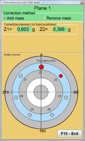
- "Dairəvi yiv"" – üyütmə çarxının balanslaşdırılması üçün istifadə olunur. Bu halda balanssızlığı aradan qaldırmaq üçün 3 əks çəki istifadə olunur.
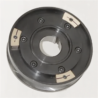
Şəkil 7.17. 3 əks çəki ilə daşlama diskinin balanslaşdırılması
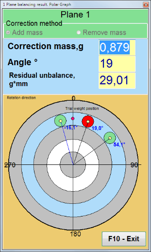
Şəkil 7.18. Uçqun daşının balanslaşdırılması. Polar qrafik.

Şəkil 7.15. Nəticə sekmesi. Düzəliş çəkisinin montajının sabit mövqeyi.
Z1 və Z2 – fırlanma istiqamətinə uyğun olaraq Z1 mövqeyindən hesablanmış, quraşdırılmış düzəldici çəkilərin mövqeləri. Z1 sınaq çəkisinin quraşdırıldığı mövqedir.
Şək. 7.16 Sabit mövqelər. Polar diaqram.
- "Kütlə mərkəzinin yerləşmə radiusu, mm"" - "Müstəvi1" - 1 müstəvisində sınaq çəkisinin radiusu. Balanslaşdırıldıqdan sonra qalıq balanssızlığa qarşı tolerantlığa uyğunluğu müəyyən etmək üçün ilkin və qalıq balanssızlığın böyüklüyünü hesablamaq tələb olunur.
- "Sınaq çəkisini Plane1-də saxlayın.""Adətən, sınaq çəkisi balanslaşdırma prosesi zamanı çıxarılır. Lakin bəzi hallarda onu çıxarmaq mümkün olmadıqda, hesablamalarda sınaq çəkisinin kütləsini nəzərə almaq üçün burada işarə qoymalısınız.".
- "Əl ilə məlumat daxil etmə"" - pəncərənin sol tərəfindəki müvafiq sahələrə vibrasiya dəyərini və fazanı əl ilə daxil etmək və "-ə keçərkən korreksiya çəkisinin kütləsini və quraşdırma bucağını hesablamaq üçün istifadə olunur."Nəticələr""tab
- Düymə ""Sessiya məlumatlarını bərpa edin"". Balanslaşdırma zamanı ölçülmüş məlumatlar session1.ini faylında saxlanılır. Ölçmə prosesi kompüterin donması və ya digər səbəblərdən kəsilibsə, bu düyməni basmaqla ölçmə məlumatlarını bərpa edə və kəsilmə anından etibarən balanslaşdırmağa davam edə bilərsiniz.
- Mandrenin ekssentrikliyi aradan qaldırılması (İndeks balanslaşdırılması) Mandrel (balans milinin) ekssentrikliyi təsirini aradan qaldırmaq üçün əlavə başlanğıc nöqtəsi ilə balanslama. Rotoru onunla münasibətdə növbə ilə 0° və 180° bucaqlarda yerləşdirin. Hər iki vəziyyətdə balanssızlıqları ölçün.
- balanslaşdıran tolerantlıq Q x mm (G-sinfələri) vahidində qalıq tarazsizlik toleranslarını daxil etmək və ya hesablamaq
- Polar qrafikdən istifadə edin Balanslaşdırma nəticələrini göstərmək üçün qütb qrafikindən istifadə edin
1-səviyyəli balanslaşdırma. Yeni rotor
Yuxarıda qeyd edildiyi kimi, ""Yeni rotor""Balanslaşdırma üçün balanslaşdırma maşınının iki sınaq yürüşü və ən azı bir trim yürüşü tələb olunur.".
Gediş#0 (İlkin gediş)
Sensorları balanslaşdırıcı rotora quraşdırdıqdan və parametr parametrlərini daxil etdikdən sonra rotorun fırlanmasını aktivləşdirmək və işləmə sürətinə çatdıqda " düyməsini basın."Yürüş#0"Ölçmələrə başlamaq üçün " düyməsinə basın. ""Qrafiklər"Sağ paneldə " sekmesi açılacaq və burada dalğa forması və vibrasiya spektri göstəriləcək. Sekmenin alt hissəsində, zaman istinadı ilə başlayan bütün nəticələrin saxlandığı bir tarix faylı saxlanılır. Diskdə bu fayl arxiv qovluğunda memo.txt adı ilə saxlanılır.
Diqqət!
Ölçməni başlamazdan əvvəl balanslama maşınının rotorunun fırlanmasını işə salmaq lazımdır (Yürüş#0) və rotor sürətinin sabit olduğuna əmin olun.
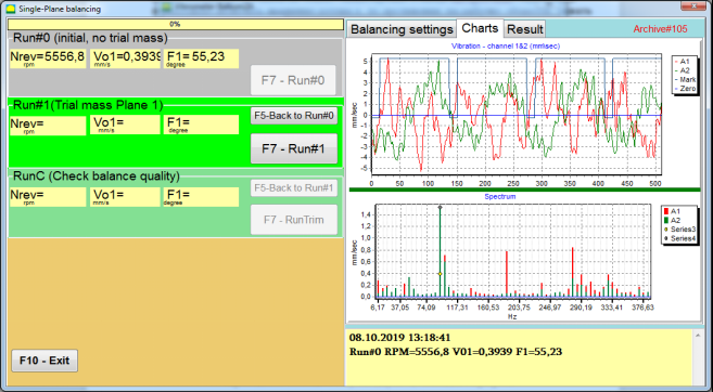
Şəkil 7.19. Bir müstəvidə balanslaşdırma. İlkin işləmə (İşləmə#0). Qrafiklər sekmesi
Ölçmə prosesi tamamlandıqdan sonra, Yürüş#0 Sol paneldəki bölmədə ölçmə nəticələri görünür - rotor sürəti (RPM), RMS (Vo1) və 1x vibrasiyanın fazası (F1).
""F5-İcra #0-a qayıt""düyməsi (və ya F5 funksiya düyməsi) Run#0 bölməsinə qayıtmaq və zərurət yarandıqda vibrasiya parametrlərini təkrar ölçmək üçün istifadə olunur.
Run#1 (Sınaq kütləsi Təyyarə 1)
"Bölməsində vibrasiya parametrlərinin ölçülməsinə başlamazdan əvvəl"Run#1 (Sınaq kütləsi Təyyarə 1), sınaq çəkisi " uyğun olaraq quraşdırılmalıdır"Sınaq kütləsi""sahə.
Sınaq çəkisi quraşdırmağın məqsədi, məlum bir çəkini məlum bir yerə (bucağa) yerləşdirildikdə rotorun vibrasiyasının necə dəyişdiyini qiymətləndirməkdir. Sınaq çəkisi vibrasiya amplitudasını ilkin amplitudanın 30%-i qədər aşağı və ya yuxarı dəyişdirməli və ya fazanı ilkin fazanın 30 dərəcəsi və ya daha çoxu qədər dəyişdirməlidir.
Əgər "" istifadə etmək lazımdırsa"Saxlanılmış koeff.""Sınaq çəkisinin sonrakı iş üçün tarazlaşdırılması zamanı onun quraşdırılma yeri (bucağı) əks etdirici işarənin yeri (bucağı) ilə eyni olmalıdır.".
Balanslaşdırıcı maşının rotorunun fırlanmasını yenidən yandırın və onun fırlanma tezliyinin sabit olduğundan əmin olun. Sonra ""F7-Qaçış#1"" düyməsini basın (və ya kompüter klaviaturasındakı F7 düyməsini basın).
Ölçmədən sonra müvafiq pəncərələrdə ""Run#1 (Sınaq kütləsi Təyyarə 1)"" bölməsində rotor sürətinin (RPM) ölçülməsinin nəticələri, eləcə də 1x vibrasiyanın RMS komponentinin (Vо1) və fazasının (F1) dəyəri göstərilir.
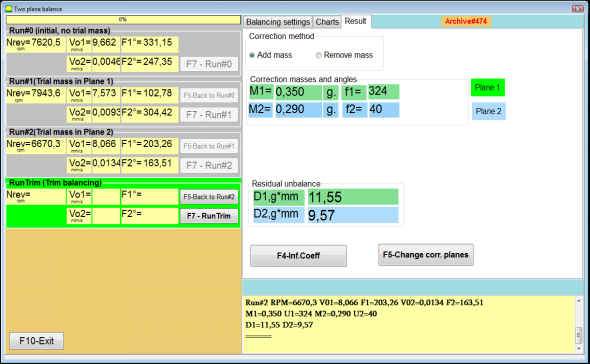
Eyni zamanda, ""nəticə""Pəncərənin sağ tərəfində "" nişanı açılır.
Bu sekmə balanssızlığı kompensasiya etmək üçün rotor üzərinə quraşdırılmalı olan korreksiya ağırlığının kütləsi və bucağının hesablanması nəticələrini göstərir.
Bundan əlavə, qütb koordinat sistemindən istifadə edildikdə, displeydə düzəliş çəkisinin kütlə dəyəri (M1) və quraşdırma bucağı (f1) göstərilir.
"İşində"Sabit Vəzifələr""Mövqelərin nömrələri (Zi, Zj) və sınaq çəkisinin bölünmüş kütləsi göstəriləcək.".
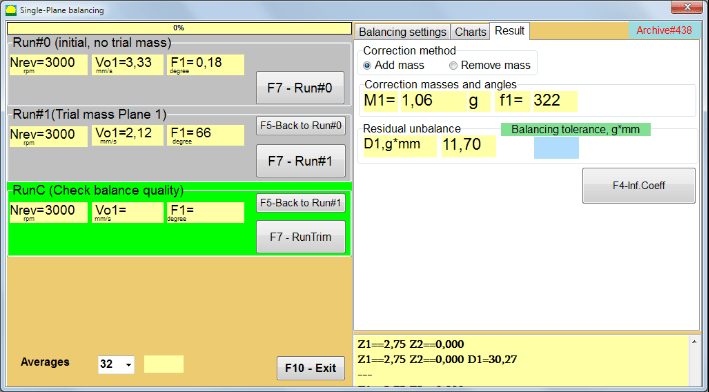
Şək. 7.20. Bir müstəvidə balanslaşdırma. Test#1 və balanslaşdırma nəticəsi.
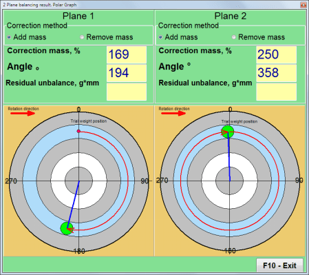
If Qütb qrafiki Yoxlanıldıqda polar diaqram göstəriləcək.
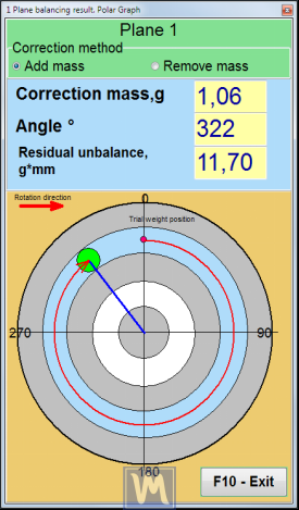
Şəkil 7.21. Balanslaşdırmanın nəticəsi. Polar qrafik.
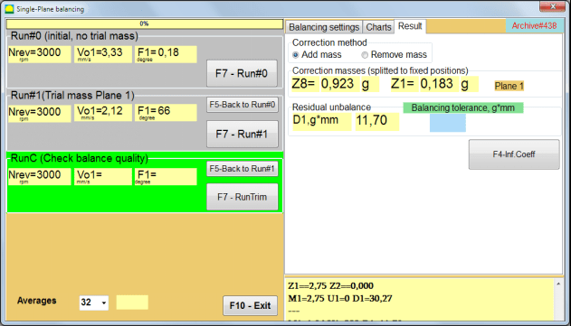
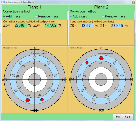
Şəkil 7.22. Balanslaşdırmanın nəticəsi. Çəkinin bölünməsi (sabit mövqelər)
Həmçinin əgər ""Qütb qrafiki"" işarələndi, Qütb qrafiki göstəriləcək.
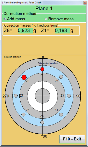
Şəkil 7.23. Sabit mövqelərə bölünmüş çəki. Polar qrafik
⚠️ Diqqət!
- İkinci mərhələdə ölçmə prosesini tamamladıqdan sonra (""Run#1 (Sınaq kütləsi Təyyarə 1)"") Balanslaşdırma maşınının fırlanmasını dayandırmaq və quraşdırılmış sınaq çəkisini çıxarmaq lazımdır. Sonra nəticə cədvəlindəki məlumatlara uyğun olaraq rotora düzəldici çəkini quraşdırın (və ya çıxarın).
Sınaq çəkisi çıxarılmayıbsa, ""Balanslaşdırma parametrləri"" sekmesini seçin və onay qutusunu aktivləşdirin""Sınaq çəkisini Plane1-də saxlayın"". Sonra ""nəticə"" sekmesi. Düzəliş çəkisinin çəkisi və quraşdırma bucağı avtomatik olaraq yenidən hesablanır.
- Düzəliş çəkisinin bucaq mövqeyi sınaq çəkisinin quraşdırıldığı yerdən həyata keçirilir. Bucağın istinad istiqaməti rotorun fırlanma istiqaməti ilə üst-üstə düşür.
- "İşində"Sabit vəziyyət""- 1st mövqe (Z1), sınaq çəkisinin quraşdırıldığı yerlə üst-üstə düşür. Mövqe nömrəsinin sayma istiqaməti rotorun fırlanma istiqamətinə uyğundur.
- Varsayılan olaraq, korreksiyaedici çəki rotora əlavə olunacaq. Bu, "" bölməsindəki etiketlə göstərilir."Add"" sahəsi. Əgər çəkini çıxarırsınızsa (məsələn, qazma ilə), " sahəsində işarə qoymalısınız"Sil"" sahəsi, bundan sonra düzəliş çəkisinin bucaq mövqeyi avtomatik olaraq 180º dəyişəcək.
Əməliyyat pəncərəsində balanslaşdırıcı rotorda korreksiya çəkisini quraşdırdıqdan sonra RunC (trim) yerinə yetirmək və yerinə yetirilən balanslaşdırmanın effektivliyini qiymətləndirmək lazımdır.
RunC (Balans keyfiyyətini yoxlayın)
⚠️ Diqqət! Ölçməni üzərində başlamazdan əvvəl CəmiMaşının rotorunun fırlanmasını işə salmaq və onun iş rejiminə (sabit fırlanma tezliyinə) keçdiyinə əmin olmaq lazımdır.
"-də vibrasiya ölçməsini aparmaq üçün"RunC (Balans keyfiyyətini yoxlayın)"" bölməsində, " düyməsini basın"F7 – RunTrim"" düyməsini basın (və ya klaviaturada F7 düyməsini basın).
Ölçmə prosesi uğurla başa çatdıqdan sonra, ""RunC (Balans keyfiyyətini yoxlayın)"Sol paneldəki " bölməsində rotor sürətinin (RPM) ölçülməsinin nəticələri, eləcə də 1x vibrasiyanın RMS komponentinin (Vo1) və fazasının (F1) dəyəri görünür.
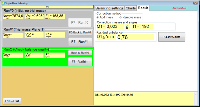
""-də"nəticə"" sekmesinde, əlavə korreksiyaedici çəkinin kütləsinin və quraşdırma bucağının hesablanmasının nəticələri göstərilir.
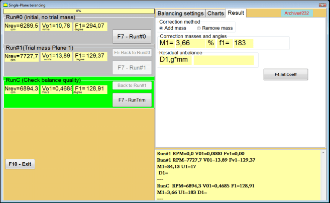
Şəkil 7.24. Bir müstəvidə balanslaşdırma. RunTrim icrası. Nəticə sekmesi
Bu çəki qalıq balanssızlığı kompensasiya etmək üçün rotor üzərində artıq quraşdırılmış korreksiya çəkinə əlavə edilə bilər. Bundan əlavə, balanslaşdırmadan sonra əldə olunan qalıq rotor balanssızlığı bu pəncərənin aşağı hissəsində göstərilir.
Balanslaşdırılan rotorun qalıq titrəmə və/və ya qalıq balanssızlıq miqdarı texniki sənədlərdə müəyyən edilmiş dözümlülük tələblərinə cavab verdikdə, balanslaşdırma prosesi başa çatdırıla bilər.
Əks halda balanslaşdırma prosesi davam edə bilər. Bu, ardıcıl yaxınlaşdırma üsuluna balanslaşdırılmış rotor üzərində düzəldici çəkini quraşdırarkən (çıxararkən) yaranan mümkün səhvləri düzəltməyə imkan verir.
Balanslaşdırıcı rotorda balanslaşdırma prosesini davam etdirərkən, parametrləri "bölməsində göstərilən əlavə düzəldici kütlə quraşdırmaq (çıxarmaq) lazımdır."Düzəliş kütlələri və bucaqları".
Təsir əmsalları (1-səviyyə)
""F4-Inf.Koeff""düyməsində""nəticə""tab, kalibrləmə işlərinin nəticələrindən hesablanmış rotor balanslaşdırma əmsallarını (Təsir əmsalları) kompüter yaddaşında görmək və saxlamaq üçün istifadə olunur.
Basıldıqda, ""Təsir əmsalları (tək müstəvi)"Kompüter ekranında kalibrləmə (sınaq) işlərinin nəticələrindən hesablanmış balanslaşdırma əmsallarının göstərildiyi " pəncərəsi görünür. Əgər bu maşının sonrakı balanslaşdırılması zamanı " istifadə edilməsi nəzərdə tutulursa"Saxlanılmış koeff.""Rejimdə bu əmsallar kompüter yaddaşında saxlanılmalıdır.".
Bunu etmək üçün "düyməsini basın"F9 - Yadda saxla""düyməsini basın və " səhifəsinin ikinci səhifəsinə keçin"Təsir əmsalı. arxiv. Tək təyyarə."

Şəkil 7.25. Birinci müstəvidə balanslama əmsalları
Sonra bu maşının adını " daxil etməlisiniz"Rotor""sütun və klikləyin""F2-Yadda saxla"Göstərilən məlumatları kompüterdə saxlamaq üçün "düyməsini basın.
Daha sonra "düyməsini basaraq əvvəlki pəncərəyə qayıda bilərsiniz"F10-Çıxış"" düyməsinə (və ya kompüter klaviaturasındakı F10 funksiya düyməsinə).
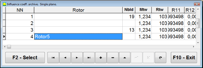
Şəkil 7.26. "Təsir əmsalı. arxiv. Tək müstəvi.""
Müvazinət hesabatı
Saxlanılan bütün məlumatları balanslaşdırdıqdan və Balans hesabatı yaradıldıqdan sonra. Siz daxili redaktorda hesabata baxa və redaktə edə bilərsiniz. Pəncərədə ""Arxivi bir müstəvidə balanslaşdırmaq"" (Şəkil 7.9) düyməsini basın ""F9 -Hesabat""balans hesabatı redaktoruna daxil olmaq üçün.
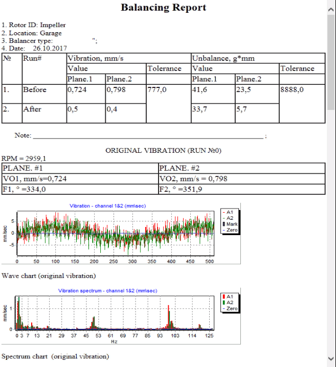
Şəkil 7.27. Balans hesabatı.
Saxlanılan əmsal. 1 müstəvidə qənaət edilmiş təsir əmsalları ilə balanslaşdırma proseduru
Ölçmə sisteminin qurulması (ilkin məlumatların daxil edilməsi)
Saxlanılan əmsal. Balanslaşdırma Balanslama əmsalları artıq müəyyən edilmiş və kompüter yaddaşına daxil edilmiş bir maşında həyata keçirilə bilər.
⚠️ Diqqət! Saxlanılmış əmsallar ilə balanslaşdırma zamanı titrəmə sensoru və faza bucağı sensoru ilkin balanslaşdırma zamanı olduğu kimi quraşdırılmalıdır.
İlkin məlumatların daxil edilməsi üçün Saxlanılan əmsal. Balanslaşdırma (ilkin vəziyyətdə olduğu kimi(""Yeni rotor"") balanslaşdırma) "-də başlayır"Tək müstəvi balanslaşdırma. Balanslaşdırma parametrləri.".
Bu halda, ""təsir əmsalları"" bölməsində, " seçin"Saxlanılmış koeff"" maddəsi. Bu halda, " ikinci səhifəsi"Təsir əmsalları arxivi. Tək müstəvi.", saxlanılan balanslaşdırma əmsallarının arxivini saxlayır.
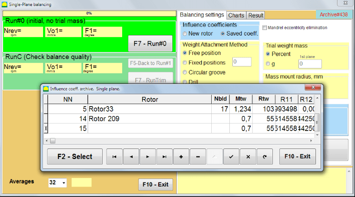
Şəkil 7.28. Bir müstəvidə saxlanmış təsir əmsalları ilə balanslaşdırma
"►" və ya "◄" idarəetmə düymələrindən istifadə edərək bu arxivin cədvəlində hərəkət edərək, bizi maraqlandıran maşının balans əmsalları ilə istədiyiniz qeydi seçə bilərsiniz. Daha sonra, bu məlumatları cari ölçmələrdə istifadə etmək üçün " düyməsini basın."F2 – Seç""düyməsi.
Bundan sonra, "-ın bütün digər pəncərələrinin məzmunu"Tək müstəvi balanslaşdırma. Balanslaşdırma parametrləri.""avtomatik olaraq doldurulur.".
İlkin məlumatların daxil edilməsini tamamladıqdan sonra ölçməyə başlaya bilərsiniz.
Saxlanmış təsir əmsalları ilə balanslaşdırma zamanı ölçmələr
Saxlanılmış təsir əmsalları ilə balanslaşdırma yalnız bir ilkin işləmə və ən azı bir sınaq işləməsi tələb edir.
⚠️ Diqqət! Ölçməni başlamazdan əvvəl rotorun fırlanmasını işə salmaq və fırlanma tezliyinin sabit olduğunu təmin etmək lazımdır.
"Vibrasiya parametrlərinin ölçülməsini həyata keçirmək üçün"Yürütmə#0 (ilkin, sınaq kütləsi olmadan)""bölmə, basın""F7 – İcra#0"" (və ya kompüter klaviaturasındakı F7 düyməsini basın).
Şək. 7.29. Bir təyyarədə saxlanmış təsir əmsalları ilə balanslaşdırma. Bir qaçışdan sonra nəticələr.
Müvafiq sahələrdə ""Yürüş#0"" bölməsində rotor sürətinin (RPM) ölçülməsinin nəticələri, RMS komponentinin (Vо1) və 1x vibrasiya fazasının (F1) dəyəri görünür.
Eyni zamanda, ""nəticə"" sekmesinde, balanssızlığı kompensasiya etmək üçün rotora quraşdırılmalı olan düzəldici çəkinin kütləsinin və bucağının hesablanmasının nəticələri göstərilir.
Bundan əlavə, qütb koordinat sistemindən istifadə edildikdə, displeydə korreksiya çəkilərinin kütlə dəyərləri və quraşdırma bucaqları göstərilir.
Düzəldici çəkini sabit mövqelərə bölmək halında balans rotorunun mövqelərinin nömrələri və onlara quraşdırılmalı çəki kütləsi göstərilir.
Bundan əlavə, balanslaşdırma prosesi ilkin balanslaşdırma üçün 7.4.2-ci bölmədə göstərilən tövsiyələrə uyğun olaraq həyata keçirilir.
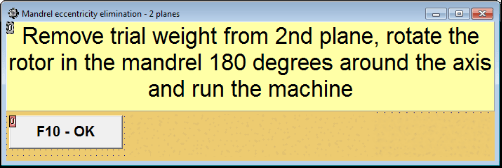
Mandrenin ekssentrikliyi aradan qaldırılması (İndeks balanslaşdırılması)
Əgər balanslaşdırma zamanı rotor silindrik mandrelə quraşdırılsa, mandrelin ekssentrikliyi əlavə xəta yarada bilər. Bu xətanı aradan qaldırmaq üçün rotoru mandrelə 180 dərəcə fırladaraq əlavə bir start aparmaq lazımdır. Bu, indeks balanslaşdırma adlanır.
İndeks balanslaşdırmasını həyata keçirmək üçün Balanset-1A proqramında xüsusi seçim təqdim olunur. "Mandrel ekssentrisitetinin aradan qaldırılması" seçimi işarələndikdə balanslaşdırma pəncərəsində əlavə RunEcc bölməsi görünür.

Şəkil 7.30. İndeks balanslaşdırılması üçün iş pəncərəsi.
Run #1 (Sınaq kütləsi Təyyarə 1) işə salındıqdan sonra bir pəncərə görünəcək
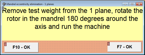
Şəkil 7.31 İndeks balanslaşdırma diqqət pəncərəsi.
Rotoru 180° dönmə ilə quraşdırdıqdan sonra Run Ecc tamamlanmalıdır. Proqram mandrel ekssentrikliyinə təsir etmədən əsl rotor balanssızlığını avtomatik hesablayacaq.
7.5 İki müstəvi balanslaşdırma
İşə başlamazdan əvvəl İki təyyarə balansı rejimində, seçilmiş ölçmə nöqtələrində maşının gövdəsinə vibrasiya sensorları quraşdırmaq və onları müvafiq olaraq ölçü vahidinin X1 və X2 girişlərinə qoşmaq lazımdır.
Ölçmə qurğusunun X3 girişinə optik faza bucağı sensoru qoşulmalıdır. Bundan əlavə, bu sensordan istifadə etmək üçün balans maşınının əlçatan rotor səthinə əks etdirici lent yapışdırılmalıdır.
Balanslaşdırma zamanı sensorların quraşdırılması yerinin seçilməsi və onların obyektdə quraşdırılması üçün ətraflı tələblər Əlavə 1-də verilmişdir.
Proqram üzərində iş ""İki təyyarə balansı""Rejim proqramların Əsas pəncərəsindən başlayır.
"Üstünə klikləyin"F3 - İki təyyarə"" düyməsini basın (və ya kompüter klaviaturasındakı F3 düyməsini basın).
Daha sonra, "F7 – Balanslaşdırma" düyməsini basın, bundan sonra kompüter ekranında işçi pəncərə görünəcək (Şəkil 7.13-ə baxın), iki müstəvidə balanslaşdırma zamanı məlumatların saxlanması üçün arxiv seçimi.
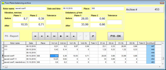
Şəkil 7.32 İki müstəvi balanslaşdırma arxiv pəncərəsi.
Bu pəncərədə balanslaşdırılmış rotorun məlumatlarını daxil etməlisiniz. " düyməsini basdıqdan sonra"F10-OK"" düyməsinə basdıqda balanslaşdırma pəncərəsi görünəcək.
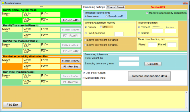
Balans parametrləri (2 müstəvi)
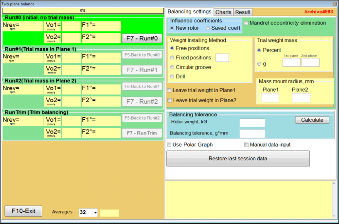
Şəkil 7.33. İki təyyarə pəncərəsində balanslaşdırma.
Pəncərənin sağ tərəfində ""Balanslaşdırma parametrləri"" balanslaşdırmadan əvvəl parametrləri daxil etmək üçün sekme.
- təsir əmsalları - Yeni rotorun balanslaşdırılması və ya saxlanılan təsir əmsallarından (balanslaşdırma əmsalları) istifadə edərək balanslaşdırılması
- Mandrel ekssentrikliyinin aradan qaldırılması - Mandrelin eksantrikliyinin təsirini aradan qaldırmaq üçün əlavə başlanğıcla balanslaşdırma
- Ağırlıq birləşdirmə üsulu - Rotorun çevrəsində ixtiyari bir yerə və ya sabit bir vəziyyətdə düzəldici çəkilərin quraşdırılması. Kütləni çıxararkən qazma üçün hesablamalar.
- "Sərbəst mövqe""- çəkilər rotorun ətrafı boyunca ixtiyari bucaq vəziyyətlərində quraşdırıla bilər.".
- "Sabit vəziyyət""- çəki rotorda sabit bucaq vəziyyətlərində, məsələn, bıçaqlarda və ya dəliklərdə (məsələn, 12 dəlik – 30 dərəcə) və s. quraşdırıla bilər. Sabit vəziyyətlərin sayı müvafiq sahəyə daxil edilməlidir. Balanslaşdırıldıqdan sonra proqram çəkini avtomatik olaraq iki hissəyə böləcək və əldə edilən kütlələri təyin etmək üçün lazım olan vəziyyətlərin sayını göstərəcək.
- Sınaq kütləsi - Sınaq çəkisi
- Plane1 / Plane2-də sınaq çəkisini buraxın - Balanslaşdırarkən sınaq çəkisini çıxarın və ya saxlayın.
- Kütlə mərkəzinin yerləşmə radiusu, mm - Montaj sınaqlarının və düzəldici çəkilərin radiusu
- balanslaşdıran tolerantlıq - Qalıq balanssızlıq tolerantlıqlarının g-mm ilə daxil edilməsi və ya hesablanması
- Polar qrafikdən istifadə edin - Balanslaşdırma nəticələrini göstərmək üçün qütb qrafikindən istifadə edin
- Əl ilə məlumat daxil etmə - Balans çəkilərinin hesablanması üçün əl ilə məlumatların daxil edilməsi
- Son sessiya məlumatlarını bərpa edin - Balanslaşdırmaya davam etmək mümkün olmadıqda, son sessiyanın ölçmə məlumatlarının bərpası.
2 təyyarə balans. Yeni rotor
Ölçmə sisteminin qurulması (ilkin məlumatların daxil edilməsi)
üçün ilkin məlumatların daxil edilməsi Yeni rotor balansı "-də"İki təyyarə balansı. Parametrlər".
Bu halda, ""təsir əmsalları"" bölməsində, " seçin"Yeni rotor"" maddə.
Bundan əlavə, "bölməsində"Sınaq kütləsi"", sınaq çəkisinin kütləsinin ölçü vahidini seçməlisiniz - ""qram""və ya""Faiz".
Ölçü vahidini seçərkən ""Faiz"", korreksiyaedici çəkinin kütləsinin bütün sonrakı hesablamaları sınaq çəkinin kütləsinə nisbətdə faiz olaraq aparılacaq.
Seçərkən ""qram""ölçü vahidi, düzəldici çəkinin kütləsinin bütün əlavə hesablamaları qramla aparılacaq. Sonra yazının sağında yerləşən pəncərələrə daxil edin""qram""rotora quraşdırılacaq sınaq çəkilərinin kütləsi.".
⚠️ Diqqət! Əgər "" istifadə etmək lazımdırsa"Saxlanılmış koeff.""İlkin balanslaşdırma zamanı əlavə iş rejimi, sınaq çəkilərinin kütləsi daxil edilməlidir qram.
Sonra "seçin"Ağırlıq birləşdirmə üsulu" - "Sirk""və ya""Sabit vəziyyət".
Əgər "seçsəniz"Sabit vəziyyət"", vəzifələrin sayını daxil etməlisiniz.
Qalıq disbalansa dözümlülüyün hesablanması (Balansın tolerantlığı)
Qalıq balanssızlığa dözümlülük (Balansın tolerantlığı) ISO 1940 Vibrasiya-da təsvir edilən prosedura uyğun olaraq hesablana bilər. Sabit (sərt) vəziyyətdə rotorlar üçün keyfiyyət tələblərini balanslaşdırın. Hissə 1. Balans tolerantlıqlarının dəqiqləşdirilməsi və yoxlanılması.

Şəkil 7.34. Balanslama toleransının hesablanması pəncərəsi
İlkin işə salınma (Run#0)
İki müstəvidə tarazlıq saxlayarkən ""Yeni rotor""rejimində balanslaşdırma üç kalibrləmə sınağı və balanslaşdırma maşınının ən azı bir sınaq sınağı tələb edir.".
Maşının ilk işə salınmasında vibrasiyanın ölçülməsi ""İki müstəvi balans""iş pəncərəsi""Yürüş#0""bölmə.
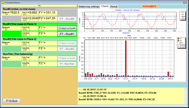
Şəkil 7.35. İlkin qaçışdan sonra iki müstəvidə tarazlamada ölçmə nəticələri.
⚠️ Diqqət! Ölçməyə başlamazdan əvvəl balans maşınının rotorunun fırlanmasını (ilk qaçış) açmaq və onun sabit sürətlə işləmə rejiminə daxil olduğundan əmin olmaq lazımdır.
Vibrasiya parametrlərini ölçmək üçün Yürüş#0 bölməsində "düyməsinə basın"F7 – İcra#0""düyməsini basın (və ya kompüter klaviaturasında F7 düyməsini basın)
Rotorun sürətinin (RPM), RMS dəyərinin (VО1, VО2) və 1x vibrasiyanın fazalarının (F1, F2) ölçülməsi nəticələri ekranın müvafiq pəncərələrində görünür. Yürüş#0 bölmə.
Run#1. Plane1-də sınaq kütləsi
Vibrasiya parametrlərini ölçməyə başlamazdan əvvəl ""Run#1. Plane1-də sınaq kütləsi"" bölməsində, balanslaşdırma maşınının rotorunun fırlanmasını dayandırmalı və üzərinə sınaq çəkisi quraşdırmalısınız, kütlə " bölməsində seçilməlidir."Sınaq kütləsi""bölmə.
⚠️ Diqqət!
- Sınaq çəkilərinin kütləsinin və onların balans maşınının rotorunda quraşdırılması yerlərinin seçilməsi məsələsi Əlavə 1-də ətraflı müzakirə olunur.
- istifadə etmək lazımdırsa Saxlanılmış koeff. Gələcək işdə rejim, sınaq çəkisinin quraşdırılması yeri mütləq faza açısını oxumaq üçün istifadə olunan işarənin quraşdırılması yeri ilə üst-üstə düşməlidir.
Bundan sonra balans maşınının rotorunun fırlanmasını yenidən açmaq və onun iş rejiminə keçdiyinə əmin olmaq lazımdır.
"Vibrasiya parametrlərini ölçmək üçün"# işə salın 1. Plane1-də sınaq kütləsi"" bölməsində, " düyməsini basın"F7 - Run#1"" düyməsini basın (və ya kompüter klaviaturasındakı F7 düyməsini basın).
Ölçmə prosesi uğurla başa çatdıqdan sonra siz ölçmə nəticələrinin sekmesine qaytarılacaqsınız.
Bu halda, müvafiq pəncərələrdə ""Çalışın#1. Plane1-də sınaq kütləsi"" bölməsində rotor sürətinin (RPM) ölçülməsinin nəticələri, eləcə də 1x vibrasiyanın RMS komponentlərinin (Vо1, Vо2) və fazalarının (F1, F2) dəyəri verilmişdir.
""# 2.Sınaq kütləsini Plane2-də işlədin""
"Bölməsində vibrasiya parametrlərini ölçməyə başlamazdan əvvəl"# 2. Təyyarə2-də sınaq kütləsini işə salın"", aşağıdakı addımları yerinə yetirməlisiniz:
- balans maşınının rotorunun fırlanmasını dayandırmaq;
- 1-ci təyyarədə quraşdırılmış sınaq çəkisini çıxarın;
- 2-ci müstəvidə sınaq çəkisi quraşdırın, kütlə "bölməsində seçilib""Sınaq kütləsi".
Bundan sonra, balans maşınının rotorunun fırlanmasını yandırın və işləmə sürətinə daxil olduğundan əmin olun.
"Vibrasiyanın ölçülməsinə başlamaq üçün"# 2. Təyyarə2-də sınaq kütləsini işə salın"" bölməsində, " düyməsini basın"F7 - # 2-ni işə salın"" düyməsini basın (və ya kompüter klaviaturasındakı F7 düyməsini basın). Sonra ""nəticə"" sekmesi açılır.
istifadə edildiyi halda Ağırlıq birləşdirmə üsulu" - "Pulsuz vəzifələr, displeydə düzəldici çəkilərin kütlə dəyərləri (M1, M2) və quraşdırma bucaqları (f1, f2) göstərilir.
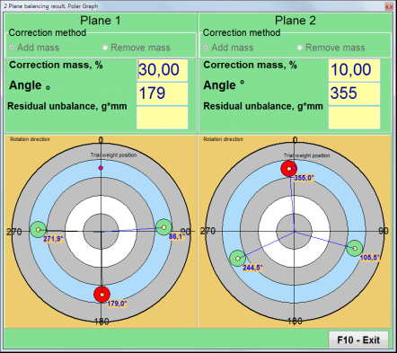
Şəkil 7.36. Düzəliş çəkilərinin hesablanmasının nəticələri – sərbəst mövqe
Şəkil 7.37. Düzəliş çəkilərinin hesablanmasının nəticələri – sərbəst mövqe. Qütb diaqramı
Çəki əlavə etmə metodundan istifadə edildiyi halda" – "Sabit Vəzifələr

Şəkil 7.38. Düzəliş çəkilərinin hesablanmasının nəticələri – sabit mövqe.
Şəkil 7.39. Düzəliş çəkilərinin hesablanmasının nəticələri – sabit mövqe. Qütb diaqramı.
Çəki Əlavəsi Metodu istifadə edildiyi təqdirdə" – ""Dairəvi yiv"
Şəkil 7.40. Düzəliş çəkilərinin hesablanmasının nəticələri – Dairəvi yiv.
⚠️ Diqqət!
- Üzərində ölçmə prosesini tamamladıqdan sonra YÜGÜRÜŞ#2 tarazlayıcı maşından, rotorun fırlanmasını dayandırın və əvvəllər quraşdırılmış sınaq çəkisini çıxarın. Sonra düzəldici çəkiləri quraşdıra (və ya çıxara) bilərsiniz.
- Qütb koordinat sistemində düzəldici çəkilərin bucaq mövqeyi rotorun fırlanma istiqamətində sınaq çəkisinin quraşdırıldığı yerdən hesablanır.
- "İşində"Sabit vəziyyət""- 1st mövqe (Z1), sınaq çəkisinin quraşdırıldığı yerlə üst-üstə düşür. Mövqe nömrəsinin sayma istiqaməti rotorun fırlanma istiqamətinə uyğundur.
- Varsayılan olaraq, korreksiyaedici çəki rotora əlavə olunacaq. Bu, "" bölməsindəki etiketlə göstərilir."Add"" sahəsi. Əgər çəkini çıxarırsınızsa (məsələn, qazma ilə), " sahəsində işarə qoymalısınız"Sil"" sahəsi, bundan sonra düzəliş çəkisinin bucaq mövqeyi avtomatik olaraq 180º dəyişəcək.
RunC (Trim run)
Düzəliş çəkisini balanslaşdırıcı rotora quraşdırdıqdan sonra RunC (trim) aparmaq və yerinə yetirilən balanslaşdırmanın effektivliyini qiymətləndirmək lazımdır.
⚠️ Diqqət! Test işində ölçməyə başlamazdan əvvəl maşının rotorunun fırlanmasını açmaq və onun işləmə sürətinə daxil olduğundan əmin olmaq lazımdır.
RunTrim (Balansın keyfiyyətini yoxlayın) bölməsində vibrasiya parametrlərini ölçmək üçün " düyməsini basın"F7 – RunTrim"" düyməsini basın (və ya kompüter klaviaturasındakı F7 düyməsini basın).
Rotorun fırlanma tezliyinin (RPM), eləcə də 1x vibrasiyanın RMS komponentinin (VO1) və fazasının (F1) qiymətinin ölçmə nəticələri göstəriləcək.
""nəticə"Əlavə korreksiyaedici çəkilərin parametrlərinin hesablanmasının nəticələrini göstərən ölçmə nəticələri cədvəli ilə işçi pəncərənin sağ tərəfində " nişanı görünür.
Bu çəkilər qalıq balanssızlığı kompensasiya etmək üçün rotorda artıq quraşdırılmış düzəldici çəkilərə əlavə edilə bilər.
Bundan əlavə, balanslaşdırmadan sonra əldə edilən qalıq rotor balanssızlığı bu pəncərənin aşağı hissəsində göstərilir.
Balanslaşdırılmış rotorun qalıq vibrasiyasının və / və ya qalıq balanssızlığının dəyərləri texniki sənədlərdə müəyyən edilmiş dözümlülük tələblərinə cavab verdikdə, balanslaşdırma prosesi başa çatdırıla bilər.
Əks halda balanslaşdırma prosesi davam edə bilər. Bu, ardıcıl yaxınlaşdırma üsuluna balanslaşdırılmış rotor üzərində düzəldici çəkini quraşdırarkən (çıxararkən) yaranan mümkün səhvləri düzəltməyə imkan verir.
Balanslaşdırıcı rotorda balanslaşdırma prosesini davam etdirərkən, parametrləri "Nəticə" pəncərəsində göstərilən əlavə düzəldici kütlə quraşdırmaq (çıxarmaq) lazımdır.
""-də"nəticə""Pəncərədə iki idarəetmə düyməsindən istifadə etmək olar -""F4-Inf.Koeff", "F5 - Düzəliş müstəvilərini dəyişdirin".
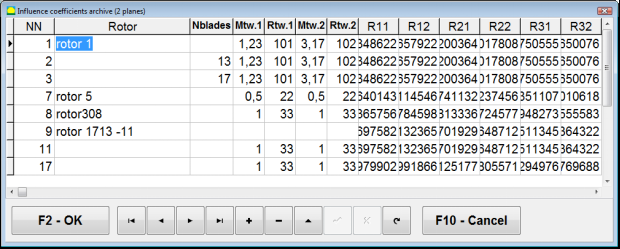
Təsir əmsalları (2 təyyarə)
""F4-Inf.Koeff""düyməsi (və ya kompüter klaviaturasındakı F4 funksiya düyməsi) iki kalibrləmə başlanğıcının nəticələrindən hesablanmış rotor balanslaşdırma əmsallarını kompüter yaddaşında görmək və saxlamaq üçün istifadə olunur.
Basıldıqda, ""Təsir əmsalları (iki müstəvi)""Kompüter ekranında ilk üç kalibrləmə başlanğıcının nəticələrinə əsasən hesablanmış balanslaşdırma əmsallarının göstərildiyi iş pəncərəsi görünür.".

Şəkil 7.41. 2 müstəvidə balanslaşdırma əmsalları olan iş pəncərəsi.
Gələcəkdə, bu tip maşının balanslaşdırılması zamanı ""Saxlanılmış koeff.""kompüter yaddaşında saxlanılan rejim və balanslaşdırma əmsalları.".
Əmsalları saxlamaq üçün " düyməsini basın"F9 - Saxla""düyməsini basın və ""Təsir əmsalları arxivi (2 təyyarə)"" pəncərələr (Şəkil 7.42-yə baxın)
Şəkil 7.42. 2 müstəvidə balanslaşdırma əmsalları olan iş pəncərəsinin ikinci səhifəsi.
Düzəliş təyyarələrini dəyişdirin
""F5 - Düzəliş müstəvilərini dəyişdirin""düyməsi, korreksiya müstəvilərinin mövqeyini dəyişdirmək lazım olduqda, korreksiyaedici çəkilərin kütlələrini və quraşdırma bucaqlarını yenidən hesablamaq lazım olduqda istifadə olunur.
Bu rejim ilk növbədə mürəkkəb formalı rotorları (məsələn, krank valları) balanslaşdırarkən faydalıdır.
Bu düymə basıldıqda, işçi pəncərə ""Korreksiya çəkilərinin kütləsinin və digər düzəliş müstəvilərinə bucağın yenidən hesablanması""kompüter ekranında göstərilir.
Bu iş pəncərəsində müvafiq şəkil üzərinə klikləməklə 4 mümkün variantdan birini seçməlisiniz.
Orijinal düzəliş müstəviləri (Н1 və Н2) yaşıl, yeni (K1 və K2) isə qırmızı rənglə qeyd olunur.
Sonra, ""Hesablama məlumatları"" bölməsinə, tələb olunan məlumatları daxil edin, o cümlədən:
- müvafiq düzəliş müstəviləri arasındakı məsafə (a, b, c);
- rotorda düzəldici çəkilərin quraşdırılması radiuslarının yeni dəyərləri (R1 ', R2').
Məlumatları daxil etdikdən sonra "düyməsini basmalısınız"F9 - hesablayın"
Hesablama nəticələri (M1, M2 kütlələri və f1, f2 düzəldici çəkilərin quraşdırma bucaqları) bu iş pəncərəsinin müvafiq bölməsində göstərilir.
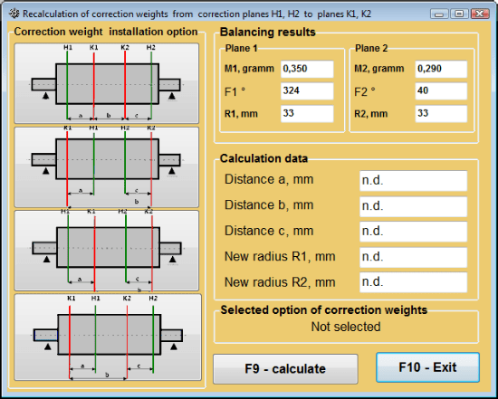
Şəkil 7.43 Düzəliş müstəvilərini dəyişdirin. Korreksiya kütləsinin və digər korreksiya müstəvilərinə bucağın yenidən hesablanması.
Saxlanılan əmsal. 2 təyyarədə balanslaşdırma
Saxlanılan əmsal. Balanslaşdırma balanslaşdırma əmsalları artıq təyin edilmiş və kompüterin yaddaşında saxlanmış maşında yerinə yetirilə bilər.
⚠️ Diqqət! Yenidən balanslaşdırarkən, vibrasiya sensorları və faza bucağı sensoru ilkin balanslaşdırma zamanı olduğu kimi quraşdırılmalıdır.
Yenidən balanslaşdırma üçün ilkin məlumatların daxil edilməsi ""İki müstəvi balans. Balans parametrləri".
Bu halda, ""təsir əmsalları"" bölməsində, " seçin"Saxlanılmış koeff.""Bölmə. Bu halda, pəncərə""Təsir əmsalları arxivi (2 təyyarə)"" əvvəllər müəyyən edilmiş balanslaşdırma əmsallarının arxivinin saxlanıldığı yerdə görünəcək.
"►" və ya "◄" idarəetmə düymələrindən istifadə edərək bu arxivin cədvəlində hərəkət edərək, bizi maraqlandıran maşının balans əmsalları ilə istədiyiniz qeydi seçə bilərsiniz. Daha sonra, bu məlumatları cari ölçmələrdə istifadə etmək üçün " düyməsini basın."F2 - OK"" düyməsini basın və əvvəlki iş pəncərəsinə qayıdın.
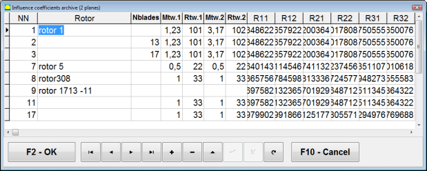
Şəkil 7.44. 2 müstəvidə balanslaşdırma əmsalları olan iş pəncərəsinin ikinci səhifəsi.
Bundan sonra, "-ın bütün digər pəncərələrinin məzmunu"2 pl-də balanslaşdırma. Mənbə məlumatları""avtomatik olaraq doldurulur.
Saxlanılan əmsal. Balanslaşdırma
"Saxlanılmış koeff.""Balanslaşdırma yalnız bir tənzimləmə başlanğıcını və balanslaşdırma maşınının ən azı bir sınaq başlanğıcını tələb edir.".
Tuning başlanğıcında vibrasiya ölçülməsi (Qaçış # 0) maşının ""2 təyyarədə balanslaşdırma""balanslaşdırma nəticələri cədvəli olan iş pəncərəsi Qaçış # 0 bölmə.
⚠️ Diqqət! Ölçməyə başlamazdan əvvəl balans maşınının rotorunun fırlanmasını açmaq və onun sabit sürətlə işləmə rejiminə daxil olduğundan əmin olmaq lazımdır.
Vibrasiya parametrlərini ölçmək üçün Qaçış # 0 bölməsində "klikləyin"F7 – İcra#0"" düyməsini basın (və ya kompüter klaviaturasındakı F7 düyməsini basın).
Rotorun sürətinin (RPM), eləcə də RMS komponentlərinin (VО1, VО2) və 1x vibrasiya fazalarının (F1, F2) dəyərinin ölçülməsi nəticələrinin müvafiq sahələrində görünür. Qaçış # 0 bölmə.
Eyni zamanda, ""nəticə"" nişanı açılır, bu da rotorun balanssızlığını kompensasiya etmək üçün ona quraşdırılmalı olan düzəldici çəkilərin parametrlərinin hesablanmasının nəticələrini göstərir.
Bundan əlavə, qütb koordinat sistemindən istifadə edildikdə, displeydə düzəldici çəkilərin kütlə dəyərləri və quraşdırma bucaqları göstərilir.
Bıçaqlarda düzəldici çəkilərin parçalanması halında, balanslaşdırıcı rotorun bıçaqlarının nömrələri və onlara quraşdırılmalı olan çəki kütləsi göstərilir.
Bundan əlavə, balanslaşdırma prosesi 7.6.1.2-ci bölmədə göstərilən tövsiyələrə uyğun olaraq həyata keçirilir. ilkin balanslaşdırma üçün.
⚠️ Diqqət!
- Ölçmə prosesi başa çatdıqdan sonra balanslaşdırılmış maşının ikinci işə salınmasından sonra onun rotorunun fırlanmasını dayandırın və əvvəlcədən təyin edilmiş sınaq çəkisini çıxarın. Yalnız bundan sonra rotorda düzəliş çəkisini quraşdırmağa (və ya çıxarmağa) başlaya bilərsiniz.
- Rotordan düzəliş çəkisinin əlavə edilməsi (və ya çıxarılması) yerinin bucaq mövqeyinin hesablanması qütb koordinat sistemində sınaq çəkisinin quraşdırılması yerində aparılır. Hesablama istiqaməti rotorun fırlanma bucağının istiqaməti ilə üst-üstə düşür.
- Bıçaqlarda balanslaşdırma zamanı – 1-ci mövqe kimi təyin edilmiş balanslaşdırılmış rotor qanadının sınaq çəkisinin quraşdırılması yeri ilə üst-üstə düşür. Kompüter ekranında göstərilən bıçağın istinad nömrəsinin istiqaməti rotorun fırlanması istiqamətində həyata keçirilir.
- Proqramın bu versiyasında, rotora korreksiya çəkisinin əlavə edilməsi standart olaraq qəbul edilir. "Əlavə" sahəsində quraşdırılmış etiket bunu göstərir. Balanssızlığın çəkini çıxarmaqla (məsələn, qazma ilə) düzəldilməsi halında, "Çıxarma" sahəsində etiket qoymaq lazımdır, sonra korreksiya çəkisinin bucaq mövqeyi avtomatik olaraq 180º-də dəyişəcək.
Mandrel eksantrikliyinin aradan qaldırılması (İndeks balanslaşdırması) - İki Müstəvi
Əgər balanslaşdırma zamanı rotor silindrik mandrelə quraşdırılsa, mandrelin ekssentrikliyi əlavə xəta yarada bilər. Bu xətanı aradan qaldırmaq üçün rotoru mandrelə 180 dərəcə fırladaraq əlavə bir start aparmaq lazımdır. Bu, indeks balanslaşdırma adlanır.
İndeks balanslaşdırmasını həyata keçirmək üçün Balanset-1A proqramında xüsusi seçim təqdim olunur. "Mandrel ekssentrisitetinin aradan qaldırılması" seçimi işarələndikdə balanslaşdırma pəncərəsində əlavə RunEcc bölməsi görünür.
Şəkil 7.45. İndeks balansı üçün iş pəncərəsi.
Run # 2 (Trial mass Plane 2) işə salındıqdan sonra pəncərə görünəcək
Şəkil 7.46. Diqqət pəncərələr
Rotoru 180° dönmə ilə quraşdırdıqdan sonra Run Ecc tamamlanmalıdır. Proqram mandrel ekssentrikliyinə təsir etmədən əsl rotor balanssızlığını avtomatik hesablayacaq.
7.6 Diaqram rejimi
"Diaqramlar" rejimində işləmək "düyməsini basmaqla Başlanğıc pəncərəsindən (Şəkil 7.1-ə baxın) başlayır"F8 – Diaqramlar". Daha sonra "İki kanalda vibrasiyanın ölçülməsi. Diaqramlar" pəncərəsi açılır (bax. Şəkil 7.19).

Şəkil 7.47. "İki kanalda vibrasiyanın ölçülməsi. Diaqramlar" əməliyyat pəncərəsi.
Bu rejimdə işləyərkən titrəmə qrafikinın dörd versiyasını çəkmək mümkündür.
Birinci versiya birinci və ikinci ölçmə kanallarında ümumi titrəmə (titrəmə sürəti) üzrə zaman funksiyasını əldə etməyə imkan verir.
İkinci versiya fırlanma tezliyi və onun daha yüksək harmonik komponentlərində baş verən vibrasiyanın (vibrasiya sürətinin) qrafiklərini əldə etməyə imkan verir.
Bu qrafiklər ümumi vibrasiya zaman funksiyasının sinxron filtirlənməsi nəticəsində əldə olunub.
Üçüncü versiya harmonik analiz nəticələri ilə birlikdə titrəmə qrafiklərini təqdim edir.
Dördüncü versiya spektral təhlilin nəticələri ilə vibrasiya qrafikini əldə etməyə imkan verir.
Ümumi vibrasiya qrafikləri
Əməliyyat pəncərəsində ümumi vibrasiya qrafiki çəkmək üçün ""İki kanalda vibrasiyanın ölçülməsi. Qrafiklər""işləmə rejimini seçmək lazımdır""Ümumi vibrasiya"" müvafiq düyməni basaraq. Daha sonra "Müddət, saniyə ilə" qutusunda vibrasiyanın ölçülməsini təyin edin, "▼" düyməsini basaraq və açılan siyahıdan ölçmə prosesinin istənilən müddətini seçin, bu müddət 1, 5, 10, 15 və ya 20 saniyəyə bərabər ola bilər;
Hazır olduqda "düyməsini basın (klikləyin)"F9"Ölçmə" düyməsini basın, sonra vibrasiya ölçmə prosesi iki kanalda eyni vaxtda başlayır.
Ölçmə prosesi tamamlandıqdan sonra iş pəncərəsində birinci (qırmızı) və ikinci (yaşıl) kanalların ümumi titrəmə vaxt funksiyası qrafikləri görünür (bax Şəkil 7.47).
Bu qrafiklərdə zaman X oxunda, vibrasiya sürətinin amplitudu (mm/s) isə Y oxunda göstərilir.
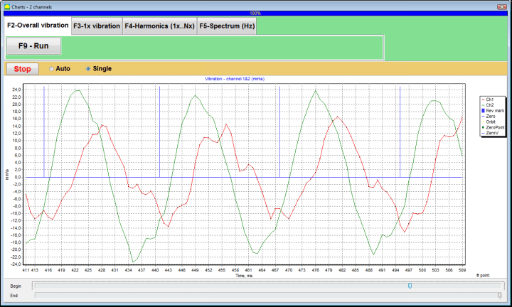
Şəkil 7.48. Ümumi vibrasiya qrafiklərinin vaxt funksiyasının çıxışı üçün əməliyyat pəncərəsi
Bu qrafiklərdə ümumi vibrasiya diaqramlarını rotorun fırlanma tezliyi ilə əlaqələndirən mavi rəngli işarələr də var. Bundan əlavə, hər bir işarə rotorun növbəti fırlanmanın başlanğıcını (sonunu) göstərir.
X-oxundakı qrafikin miqyasını dəyişmək lazım olduqda, 7.20-ci fiqurda oxla göstərilən sürgüçdən istifadə etmək olar.
1x vibrasiya qrafikləri
Əməliyyat pəncərəsində 1x vibrasiya qrafiki çəkmək üçün ""İki kanalda vibrasiyanın ölçülməsi. Qrafiklər""işləmə rejimini seçmək lazımdır""1x titrəmə""müvafiq düyməni basaraq.
Daha sonra "1x vibrasiya" əməliyyat pəncərəsi görünür.
"düyməsini basın (klikləyin)"F9"Ölçmə" düyməsini basın, sonra vibrasiya ölçmə prosesi iki kanalda eyni vaxtda başlayır.
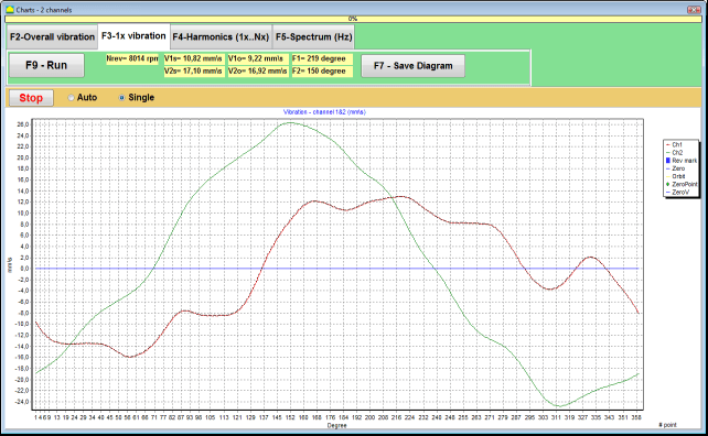
Şəkil 7.49. 1x vibrasiya qrafiklərinin çıxışı üçün əməliyyat pəncərəsi.
Ölçmə prosesinin tamamlanmasından və nəticələrin riyazi hesablanmasından (ümumi titrəmənin zaman funksiyasının sinxron filtirlənməsi) sonra əsas pəncərədə dövrə bərabər olan müddətdə nümayiş etdirilir Rotorun bir dövrü dərc olunmuş cədvəllər 1x titrəmə iki kanalda
Bu halda birinci kanalın diaqramı qırmızı, ikinci kanalın diaqramı isə yaşıl rəngdə göstərilib. Bu diaqramlarda rotorun fırlanma bucağı (işarədən işarəyə) X-oxda, vibrasiya sürətinin amplitudu (mm/s) isə Y-oxda əks etdirilib.
Bundan əlavə, iş pəncərəsinin yuxarı hissəsində (düymənin sağında ""F9 - ölçün"") hər iki kanalın vibrasiya ölçmələrinin ədədi dəyərləri, ""Vibrasiya ölçən""rejimi göstərilir.
Xüsusilə: ümumi titrəməyin RMS dəyəri (V1-lər, V2-lər), RMS-in miqyarı (V1o, V2o) və faza (Fi, Fj) 1x titrəmə və rotor sürəti (Nrev).
Harmonik analizin nəticələri ilə vibrasiya qrafikləri
Əməliyyat pəncərəsində harmonik analizin nəticələri ilə bir qrafik qurmaq ""İki kanalda vibrasiyanın ölçülməsi. Qrafiklər""işləmə rejimini seçmək lazımdır""Harmonik analiz""müvafiq düyməni basaraq.
Sonra müvəqqəti funksiya diaqramlarının və dövrü rotorun fırlanma tezliyinə bərabər və ya çox olan vibrasiya harmonik aspektlərinin spektrinin eyni vaxtda çıxarılması üçün əməliyyat pəncərəsi görünür.
Diqqət!
Bu rejimdə işləyərkən sensorun quraşdırıldığı maşınların rotor tezliyi ilə ölçmə prosesini sinxronlaşdıran faz bucağı sensorundan istifadə etmək zəruridir.
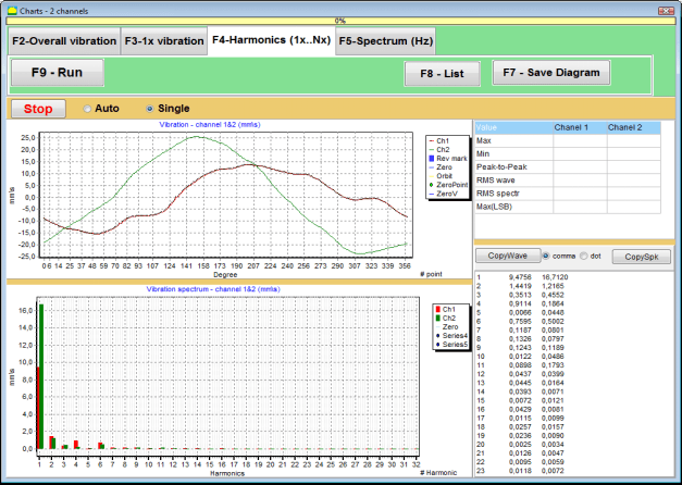
Şəkil 7.50. 1x vibrasiyanın işləyən pəncərə harmonikləri.
Hazır olduqda "düyməsini basın (klikləyin)"F9"Ölçmə" düyməsini basın, sonra vibrasiya ölçmə prosesi iki kanalda eyni vaxtda başlayır.
Ölçmə prosesi başa çatdıqdan sonra əməliyyat pəncərəsində vaxt funksiyasının qrafikləri (daha yüksək diaqram) və 1x vibrasiyanın harmonikası (aşağı diaqram) görünür.
Harmonik komponentlərin sayı X oxunda, titrəmə sürətinin RMS-i isə Y oxunda göstərilir.
Vibrasiya zaman domeninin və spektrinin qrafikləri
Spektr qrafiki çəkmək üçün "" istifadə edin"F5-Spektr""tab:
Sonra dalğa diaqramlarının və vibrasiya spektrinin eyni vaxtda çıxarılması üçün əməliyyat pəncərəsi görünür.

Şəkil 7.51. Vibrasiya spektrinin çıxışı üçün əməliyyat pəncərəsi.
Hazır olduqda "düyməsini basın (klikləyin)"F9"Ölçmə" düyməsini basın, sonra vibrasiya ölçmə prosesi iki kanalda eyni vaxtda başlayır.
Ölçmə prosesi başa çatdıqdan sonra əməliyyat pəncərəsində vaxt funksiyasının qrafikləri (daha yüksək diaqram) və vibrasiya spektri (aşağı diaqram) görünür.
Titrəmə tezliyi X-oxunda, titrəmə sürətinin RMS-i isə Y-oxunda göstərilir.
Bu halda birinci kanalın qrafiki qırmızı, ikinci kanalın qrafiki isə yaşıl rəngdə göstərilib.
8. Cihazın istismarı və texniki xidməti üzrə ümumi təlimatlar
8.1 Balanslaşdırma Keyfiyyət Meyarları (ISO 2372 Standartı)
Balanslaşdırmanın keyfiyyəti ISO 2372 standartı ilə müəyyən edilmiş vibrasiya səviyyələrindən istifadə etməklə qiymətləndirilə bilər. Aşağıdakı cədvəl müxtəlif maşın sinifləri üçün məqbul vibrasiya səviyyələrini göstərir:
| Maşın sinfi | Yaxşı (mm/san RMS) |
Məqbul (mm/san RMS) |
Hələ də məqbuldur (mm/san RMS) |
Qəbuledilməz (mm/san RMS) |
|---|---|---|---|---|
| 1-ci sinif Sərt təməllər üzərində kiçik maşınlar (15 kVt-a qədər mühərriklər) |
< 0.7 | 0.7 - 1.8 | 1.8 - 4.5 | 4.5 |
| 2-ci sinif Əsassız orta maşınlar (mühərriklər 15-75 kVt), sürücü mexanizmləri 300 kVt-a qədər |
< 1.1 | 1.1 - 2.8 | 2.8 - 7.1 | 7.1 |
| 3-cü sinif Sərt təməllər üzərində böyük maşınlar (300 kVt-dan çox avadanlıq) |
< 1.8 | 1.8 - 4.5 | 4.5 - 11 | on bir |
| 4-cü sinif Yüngül təməl üzərində böyük maşınlar (300 kVt-dan çox avadanlıq) |
2,8-dən az | 2.8 - 7.1 | 7.1 - 18 | on səkkiz |
Qeyd: Bu dəyərlər balanslaşdırma keyfiyyətini qiymətləndirmək üçün təlimat verir. Həmişə tətbiqiniz üçün xüsusi avadanlıq istehsalçısının spesifikasiyasına və müvafiq standartlara istinad edin.
8.2 Baxım Tələbləri
🔧 Daimi Baxım
- ✓Sensorların istehsalçının spesifikasiyasına uyğun olaraq müntəzəm kalibrlənməsi
- ✓Sensorları təmiz və maqnit qalıqlarından təmiz saxlayın
- ✓İstifadə edilmədikdə avadanlığı qoruyucu qutuda saxlayın
- ✓Lazer sensorunu tozdan və nəmdən qoruyun
- ✓Kabel birləşmələrini aşınma və ya zədələnmə üçün mütəmadi olaraq yoxlayın
- ✓İstehsalçı tərəfindən tövsiyə edildiyi kimi proqramı yeniləyin
- ✓Mühüm balanslaşdırma məlumatlarının ehtiyat nüsxələrini saxlayın
📋 AB Texniki Xidmət Standartları
Avadanlıqlara qulluq aşağıdakılara uyğun olmalıdır:
- EN ISO 9001: Keyfiyyət idarəetmə sistemlərinə tələblər
- EN 13306: Baxım terminologiyası və tərifləri
- EN 15341: Əsas performans göstəricilərinə qulluq
- Aİ maşın direktivinə uyğun olaraq müntəzəm təhlükəsizlik yoxlamaları
ƏLAVƏ 1. ROTORUN BALANSLANMASI
Rotor müəyyən bir ox ətrafında fırlanan və dayaqlardakı daşıyıcı səthləri ilə tutulan bir cisimdir. Rotorun daşıyıcı səthləri ağırlıqları diyirlənən və ya sürüşən yastıqlar vasitəsilə dayaqlara ötürür. "Daşıyıcı səth" termini istifadə edərkən sadəcə rulonun* və ya rulonun əvəzedici səthlərinə istinad edirik.
*Jurnal (alman dilində Zapfen "jurnal", "sancaq" deməkdir) - tutucu (yataq qutusu) tərəfindən daşınan valın və ya oxun bir hissəsidir.
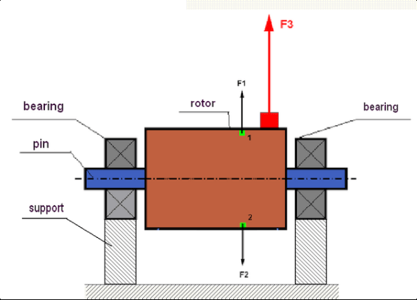
şək.1 Rotor və sentrifuqal qüvvələr.
Mükəmməl balanslaşdırılmış rotorun kütləsi fırlanma oxuna görə simmetrik şəkildə paylanıb. Bu o deməkdir ki, rotorun istənilən elementi fırlanma oxuna görə simmetrik yerləşən başqa bir elementlə uyğun gələ bilər. Fırlanma zamanı hər bir rotor elementi radial istiqamətdə (rotorun fırlanma oxuna dik) yönəlmiş mərkəzdənqaçma qüvvəsinin təsirinə məruz qalır. Müvazinətli rotor halında rotorun istənilən elementinə təsir edən sentrifuqal qüvvə simmetrik elementə təsir edən sentrifuqal qüvvə ilə tarazlanır. Məsələn, 1 və 2-ci elementlər (şək. 1-də göstərilmiş və yaşıl rənglə boyanmış) F1 və F2 sentrifuqal qüvvələrinin təsirinə məruz qalır: onlar qiymətcə bərabər və istiqamətcə tamamilə əksdir. Bu, rotorun bütün simmetrik elementləri üçün doğrudur və beləliklə, rotora təsir edən ümumi sentrifuqal qüvvə 0-a bərabər olur, yəni rotor balanslıdır. Lakin rotorun simmetriyası pozularsa (Şəkil 1-də assimmetrik element qırmızı rənglə işarələnib), o zaman balanssız sentrifuqal qüvvə F3 rotor üzərində təsir etməyə başlayır.
Fırlanan zaman bu qüvvə rotorun fırlanması ilə birlikdə istiqaməti dəyişir. Bu qüvvədən yaranan dinamik yük rulmanlara ötürülür və bu da onların sürətlənmiş aşınmasına səbəb olur. Bundan əlavə, bu dəyişən qüvvənin təsiri altında dayaqların və rotorun sabitləndiyi bünövrənin tsiklik deformasiyası baş verir ki, bu da vibrasiya yaradır. Rotorun balanssızlığını və onu müşayiət edən vibrasiyanı aradan qaldırmaq üçün rotorun simmetriyasını bərpa edəcək balanslaşdırıcı kütlələri təyin etmək lazımdır.
Rotorun balanslaşdırılması balans kütlələri əlavə etməklə balanssızlığı aradan qaldırmaq əməliyyatıdır.
Dengəlləmə tapşırığı bir və ya bir neçə dengəlləmə kütləsinin quraşdırılma dəyərini və yerlərini (bucaqlarını) tapmaqdır.
Rotorların növləri və balanssızlığı
Rotor materialının möhkəmliyi və ona təsir edən mərkəzdənqaçma qüvvələrinin böyüklüyü nəzərə alındıqda, rotorlar iki növə bölünür: sərt və elastik.
Mərkəzdənqaçma qüvvəsinin təsiri altında iş şəraitində sərt rotorlar bir qədər deformasiyaya uğraya bilər, lakin hesablamalarda bu deformasiyanın təsiri laqeyd qala bilər.
Digər tərəfdən, elastik rotorların deformasiyası heç vaxt nəzərə alınmamalıdır. Elastik rotorların deformasiyası balanslaşdırma probleminin həllini mürəkkəbləşdirir və sərt rotorların balanslaşdırılması tapşırığı ilə müqayisədə digər riyazi modellərdən istifadəni tələb edir. Eyni rotorun aşağı fırlanma sürətlərində sərt, yüksək sürətlərdə isə elastik rotor kimi davrandığını qeyd etmək vacibdir. Daha sonra yalnız sərt rotorların balanslaşdırılmasını nəzərdən keçirəcəyik.
Rotorun uzunluğu boyunca balanssız kütlələrin paylanmasından asılı olaraq iki növ balanssızlığı ayırd etmək olar - statik və dinamik. Eyni şey statik və dinamik rotor balansına da aiddir.
Rotorun statik tarazlığının pozulması rotorun fırlanması olmadan baş verir. Başqa sözlə, rotor cazibə qüvvəsinin təsiri altında olduqda sakit olur və əlavə olaraq "ağır nöqtəni" aşağı çevirir. Statik tarazlığı pozulmuş rotorun nümunəsi Şəkil 2-də təqdim olunur.

Şək.2
Dinamik tarazsızlıq yalnız rotor fırlandıqda yaranır.
Dəyişkən balanssızlığa malik rotor nümunəsi Şəkil 3-də göstərilmişdir.
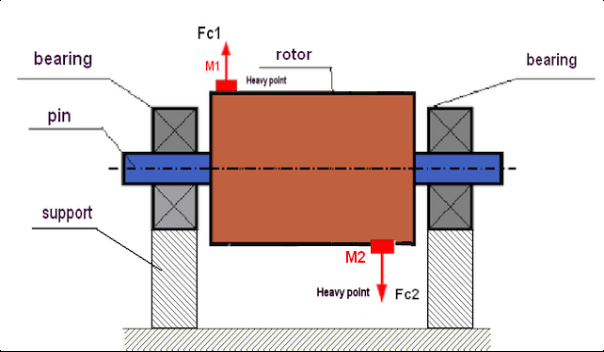
Şək.3. Rotorun dinamik tarazsızlığı – sentrifuqal qüvvələr cütü
Bu halda, balanssız bərabər kütləli M1 və M2 müxtəlif səthlərdə - rotorun uzunluğu boyunca müxtəlif yerlərdə yerləşir. Statik vəziyyətdə, yəni rotor fırlanmadıqda, rotor yalnız cazibə qüvvəsindən təsirlənə bilər və buna görə də kütlələr bir-birini tarazlaşdıracaq. Dinamikada rotor fırlandıqda, M1 və M2 kütlələri mərkəzdənqaçma qüvvələri FЎ1 və FЎ2-dən təsirlənməyə başlayır. Bu qüvvələr dəyərlərinə görə bərabərdir və istiqamətinə görə əksdir. Lakin, onlar valın uzunluğu boyunca müxtəlif yerlərdə yerləşdikləri və eyni xətt üzərində olmadıqları üçün qüvvələr bir-birini kompensasiya etmir. FЎ1 və FЎ2 qüvvələri rotora təsir edən bir moment yaradır. Buna görə də bu balanssızlığın başqa bir adı "ani"dir. Müvafiq olaraq, kompensasiya olunmayan mərkəzdənqaçma qüvvələri yatak dayaqlarına təsir göstərir ki, bu da etibar etdiyimiz qüvvələri əhəmiyyətli dərəcədə aşa bilər və həmçinin yatakların xidmət müddətini azalda bilər.
Bu tip balanssızlıq yalnız rotorun fırlanması zamanı dinamikada baş verdiyindən, buna dinamik adlanır. Statik balanslaşdırmada (və ya "bıçaqlarda" deyilən şəkildə) və ya digər oxşar üsullarla aradan qaldırıla bilməz. Dinamik balanssızlığı aradan qaldırmaq üçün M1 və M2 kütlələrindən yaranan momentə bərabər və əks istiqamətdə dəyərə malik bir moment yaradan iki kompensasiya çəkisi təyin etmək lazımdır. Kompensasiya kütlələrinin mütləq M1 və M2 kütlələrinə qarşı qoyulması və dəyərə görə onlara bərabər olması vacib deyil. Ən əsası, onlar balanssızlıq anında tam kompensasiya edən bir moment yaratmalıdırlar.
Ümumiyyətlə, M1 və M2 kütlələri bir-birinə bərabər olmaya bilər, buna görə də statik və dinamik balanssızlığın kombinasiyası olacaq. Nəzəri olaraq sübut edilmişdir ki, sərt rotorun balanssızlığını aradan qaldırmaq üçün rotorun uzunluğu boyunca aralı iki ağırlıq quraşdırmaq lazımdır və kifayətdir. Bu çəkilər həm dinamik balanssızlıqdan yaranan momenti, həm də kütlənin rotor oxuna nisbətən asimmetriyasından yaranan mərkəzdənqaçma qüvvəsini (statik balanssızlıq) kompensasiya edəcək. Həmişəki kimi, dinamik balanssızlıq vallar kimi uzun rotorlar üçün, statik isə dar rotorlar üçün tipikdir. Lakin, dar rotor oxa nisbətən əyri şəkildə və ya daha pisi, deformasiya olunmuş şəkildə (sözdə "təkər yellənmələri") quraşdırılıbsa, bu halda düzgün kompensasiya momenti yaradan korreksiyaedici ağırlıqları təyin etmək çətin olduğuna görə dinamik balanssızlığı aradan qaldırmaq çətin olacaq (Şəkil 4-ə baxın).
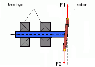
Şək.4 Titrəmə edən təkərin dinamik balanslaşdırılması
Dar rotor çiyni qısa bir moment yaratdığından, böyük bir kütlənin korreksiya çəkilərini tələb edə bilər. Lakin eyni zamanda, korreksiyaedici kütlələrdən gələn mərkəzdənqaçma qüvvələrinin təsiri altında dar rotorun deformasiyası ilə əlaqəli əlavə bir "induksiya edilmiş balanssızlıq" mövcuddur.
Məsələyə baxın:
""Sərt rotorların balanslaşdırılması üzrə metodiki göstərişlər"" ISO 1940-1:2003 Mexaniki vibrasiya – Sabit (sərt) vəziyyətdəki rotorlar üçün balans keyfiyyəti tələbləri – 1-ci hissə: Balans toleranslarının spesifikasiyası və təsdiqi
Bu, dar ventilyator təkərlərində görünür; onlar güc balanssızlığına əlavə olaraq aerodinamik balanssızlığa da təsir göstərir. Və aerodinamik balanssızlığın, əslində aerodinamik qüvvənin rotorun bucaq sürətinə birbaşa proporsional olduğunu nəzərə almaq vacibdir, və onu kompensasiya etmək üçün bucaq sürətinin kvadratına proporsional olan korreksiyaedici kütlənin mərkəzqaçma qüvvəsindən istifadə olunur. Buna görə də balanslaşdırma effekti yalnız müəyyən bir balanslaşdırma tezliyində baş verə bilər. Digər sürətlərdə əlavə boşluq yaranar. Eyni şeyi elektromaqnit mühərrikindəki elektromaqnit qüvvələrinə də demək olar; onlar da bucaq sürətinə nisbətən proporsionaldır. Başqa sözlə, heç bir balanslaşdırma üsulu mexanizmin titrəməsinə səbəb olan bütün amilləri aradan qaldıra bilməz.
Vibrasiyanın əsasları
Vibrasiya mexanizm dizaynının siklik həyəcanverici qüvvənin təsirinə reaksiyasıdır. Bu qüvvə fərqli təbiətə malik ola bilər.
- Rotorun balanssızlığından yaranan mərkəzdənqaçma qüvvəsi "ağır nöqtəyə" təsir edən kompensasiya olunmamış bir qüvvədir. Xüsusilə bu qüvvə və onun yaratdığı titrəmə rotorun balanslaşdırılması ilə aradan qaldırılır.
- "Həndəsi" təbiətə malik olan və birləşdirici hissələrin istehsalı və quraşdırılması zamanı yaranan səhvlərdən yaranan qarşılıqlı təsir qüvvələri. Bu qüvvələr, məsələn, val dirəyinin yuvarlaq olmaması, dişlilərdə diş profillərindəki səhvlər, yastıq yollarının dalğalı olması, birləşdirici valların səhv düzülüşü və s. səbəbindən yarana bilər. Boyunların yuvarlaq olmaması halında, val oxu valın fırlanma bucağından asılı olaraq dəyişəcək. Bu titrəmə rotor sürətində özünü göstərsə də, balanslaşdırma ilə onu aradan qaldırmaq demək olar ki, mümkün deyil.
- Impeller ventilyatorlarının və digər pərdəli mexanizmlərin fırlanması nəticəsində yaranan aerodinamik qüvvələr. Hidravlik nasos impellerlərinin, turbinlərin və s. fırlanması nəticəsində yaranan hidrodinamik qüvvələr.
- Nəticədə elektrik maşınlarının işindən yaranan elektromaqnit qüvvələr, məsələn, rotor sarımlarının asimmetriyası, qısaqapanmış döngələrin olması və s.
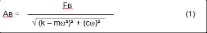
Titrəmənin böyüklüyü (məsələn, AB amplitudası) yalnız dairəvi tezlik ω ilə mexanizmə təsir edən oyadıcı qüvvə Ft-nin böyüklüyündən deyil, həm də mexanizmin konstruksiyasının sərtliyi k, kütləsi m və sönmə əmsalı C-dən asılıdır.
Vibrasiyanı və balans mexanizmlərini ölçmək üçün müxtəlif növ sensorlardan istifadə edilə bilər, o cümlədən:
- Vibrasiya sürətlənməsini ölçmək üçün nəzərdə tutulmuş mütləq vibrasiya sensorları (akselerometrlər) və vibrasiya sürətini ölçən vibrasiya sensorları;
- vibrasiyanı ölçmək üçün nəzərdə tutulmuş burulğan cərəyanı və ya tutumlu nisbi vibrasiya sensorları.
Bəzi hallarda (mexanizmin quruluşu imkan verdikdə) qüvvə sensorlarından onun vibrasiya çəkisini yoxlamaq üçün də istifadə etmək olar.
Xüsusilə, onlar sərt dayaqlı balanslaşdırma maşınlarının dayaqlarının titrəmə çəkisini ölçmək üçün geniş istifadə olunur.
Beləliklə, vibrasiya mexanizmin xarici qüvvələrin təsirinə verdiyi reaksiyadır. Vibrasiyanın miqdarı yalnız mexanizmə təsir edən qüvvənin böyüklüyündən deyil, həm də mexanizmin sərtliyindən asılıdır. Eyni böyüklüyə malik iki qüvvə fərqli vibrasiyalara səbəb ola bilər. Sərt dayaq strukturuna malik mexanizmlərdə hətta kiçik vibrasiya belə daşıyıcı vahidlərə dinamik çəkilər vasitəsilə əhəmiyyətli təsir göstərə bilər. Buna görə sərt ayaqlara malik mexanizmləri balanslaşdırarkən qüvvə sensorları və vibrasiya (vibro-təcilölçənlər) tətbiq edilir. Vibrasiya sensorları yalnız nisbətən elastik dayağa malik mexanizmlərdə, balanssız mərkəzdənqaçma qüvvələrin təsiri dayaqlarda nəzərəçarpan deformasiya və vibrasiyaya səbəb olduqda istifadə olunur. Qüvvə sensorları isə sərt dayaqlarda, balanssızlıqdan yaranan əhəmiyyətli qüvvələr ciddi vibrasiyaya səbəb olmasa belə tətbiq edilir.
Quruluşun rezonansı
Biz əvvəllər rotorların sərt və elastik növlərə bölündüyünü qeyd etmişdik. Rotorun sərtliyi və ya elastikliyi onun yerləşdiyi dayağın (bünövrənin) sərtliyi və ya hərəkətliliyi ilə qarışdırılmamalıdır. Centrifuqal qüvvələrin təsiri altında deformasiyası (əyilməsi) nəzərə alınmayacaq dərəcədə az olduqda rotor sərt sayılır. Elastik rotorun deformasiyası nisbətən böyükdür: onu nəzərə almamaq olmaz.
Bu yazıda biz yalnız sərt rotorların balansını öyrənirik. Sərt (deformasiyaya uğramayan) rotor öz növbəsində sərt və ya daşınan (yumşalana bilən) dayaqlarda yerləşdirilə bilər. Aydındır ki, dayaqların bu sərtliyi/hərəkətliliyi rotorun fırlanma sürətindən və yaranan mərkəzdənqaçma qüvvələrinin böyüklüyündən asılı olaraq nisbidir. Adi sərhəd rotor dayaqlarının/təməllərinin sərbəst salınımlarının tezliyidir. Mexanik sistemlər üçün sərbəst rəqslərin forması və tezliyi mexaniki sistemin elementlərinin kütləsi və elastikliyi ilə müəyyən edilir. Yəni təbii rəqslərin tezliyi mexaniki sistemin daxili xarakteristikasıdır və xarici qüvvələrdən asılı deyildir. Tarazlıq vəziyyətindən kənara çıxan dayaqlar elastikliyə görə tarazlıq vəziyyətinə qayıtmağa meyllidirlər. Lakin kütləvi rotorun ətalətinə görə bu proses sönümlü salınımlar xarakteri daşıyır. Bu salınımlar rotor dəstək sisteminin öz rəqsləridir. Onların tezliyi rotor kütləsinin nisbətindən və dayaqların elastikliyindən asılıdır.
Rotor fırlanmağa başladıqda və onun fırlanma tezliyi öz təbii osilasyonlarının tezliyinə yaxınlaşdıqda, vibrasiya amplitudu kəskin artır və bu, strukturun dağıdılmasına belə səbəb ola bilər.
Mexaniki rezonans fenomeni mövcuddur. Rezonans bölgəsində fırlanma sürətinin 100 rpm dəyişməsi vibrasiyanın on dəfə artmasına səbəb ola bilər. Bu halda (rezonans bölgəsində) vibrasiya fazası 180° dəyişir.
Əgər mexanizmin dizaynı zəif dizayn edilibsə və rotorun işləmə sürəti təbii salınım tezliyinə yaxındırsa, qəbuledilməz dərəcədə yüksək vibrasiya səbəbindən mexanizmin işləməsi qeyri-mümkün olur. Standart balanslaşdırma metodları da mümkün deyil, çünki parametrlər fırlanma sürətində cüzi bir dəyişiklik olsa belə kəskin şəkildə dəyişir. Rezonans balanslaşdırma sahəsində xüsusi metodlardan istifadə olunur, lakin onlar bu məqalədə yaxşı təsvir edilməyib. Mexanizmin təbii salınımlarının tezliyini rotor söndürüldükdə və ya zərbə ilə sistemin zərbəyə reaksiyasının sonrakı spektral təhlili ilə təyin edə bilərsiniz. "Balans-1" bu metodlarla mexaniki strukturların təbii tezliklərini təyin etmək imkanı verir.
Rezonans tezliyindən yüksək iş sürətinə malik mexanizmlər, yəni rezonans rejimində işləyən mexanizmlər üçün dayaqlar hərəkətli sayılır və əsasən struktur elementlərinin sürətlənməsini ölçən vibrasiya akselerometrlərindən ibarət vibrasiya sensorlarından istifadə olunur. Sərt dayaq rejimində işləyən mexanizmlərdə isə dayaqlar sərt sayılır və bu halda qüvvə sensorlarından istifadə edilir.
Mexanik sistemin xətti və qeyri-xətti modelləri
Sərt rotorların balanslaşdırılması zamanı hesablama aparmaq üçün riyazi modellər (xətti) istifadə olunur. Modelin xəttiliyi o deməkdir ki, modellər bir-birindən birbaşa nisbətdə (xətli) asılıdır. Məsələn, rotorun kompensasiya olunmamış kütləsi iki dəfə artırıldıqda, titrəmə dəyəri də müvafiq olaraq iki dəfə artacaq. Sərt rotorlar deformasiya olmadığından, onlar üçün xətti model istifadə etmək olar. Əyilə bilən rotorlar üçün xətti model istifadə etmək artıq mümkün deyil. Əyilə bilən rotor üçün fırlanma zamanı ağır nöqtənin kütləsinin artması əlavə deformasiya yaradacaq və kütləyə əlavə olaraq ağır nöqtənin radiusu da artacaq. Buna görə də, əyilə bilən rotor üçün vibrasiya iki dəfədən çox artacaq və adi hesablamalar üsulları işləməyəcək. Həmçinin, modelin xəttiliyinin pozulması dayaqların böyük deformasiyalarda elastikliyinin dəyişməsinə səbəb ola bilər; məsələn, kiçik deformasiyalarda dayaqlar bəzi struktur elementlərini işə salır, böyük deformasiyalarda isə işə digər struktur elementləri cəlb olunur. Buna görə də bazada bərkidilməmiş və, məsələn, sadəcə döşəməyə qoyulmuş mexanizmləri balanslaşdırmaq mümkün deyil. Əhəmiyyətli vibrasiyalar zamanı balanssızlıq qüvvəsi mexanizmi döşəmədən ayıra bilər və bu, sistemin sərtlik xarakteristikalarını əhəmiyyətli dərəcədə dəyişdirir. Mühərrik ayaqları möhkəm bərkidilməlidir, bolt birləşdiriciləri sıxılmalı, yaylıqların qalınlığı kifayət qədər sərtlik təmin etməli və s. Bozulan rulmanlar zamanı şaftın əhəmiyyətli dərəcədə yerləşməsi və onun zərbələri mümkündür ki, bu da xəttiliyin pozulmasına və yüksək keyfiyyətli balanslaşdırmanın mümkünsüzlüyünə səbəb olacaq.
Balanslaşdırma üsulları və qurğuları
Yuxarıda qeyd edildiyi kimi, balanslaşdırma rotorun əsas mərkəzi inersiya oxunu fırlanma oxu ilə birləşdirmə prosesidir.
Göstərilən proses iki cür icra edilə bilər.
Birinci üsul rotor oxlarının emalını əhatə edir; bu emal oxların bölmə mərkəzlərinin rotorun əsas mərkəzi inersiya oxu ilə kəsişməsini təmin edəcək şəkildə həyata keçirilir. Bu texnika praktikada nadir hallarda istifadə olunur və bu məqalədə ətraflı müzakirə olunmayacaq.
İkinci (ən çox yayılmış) üsul rotor üzərində korreksiya kütlələrinin yerləşdirilməsi, quraşdırılması və ya çıxarılmasını əhatə edir; bu kütlələr rotorun inersiya oxunu onun fırlanma oxuna mümkün qədər yaxınlaşdırmaq üçün yerləşdirilir.
Balanslaşdırma zamanı korreksiya kütlələrinin yerləşdirilməsi, əlavə edilməsi və ya çıxarılması müxtəlif texnoloji əməliyyatlarla həyata keçirilə bilər: qazma, frezələmə, səthləmə, qaynaq, vintlərin sıxılması və ya açılması, lazer şüası və ya elektron şüası ilə yandırma, elektroliz, elektromaqnit qaynağı və s.
Tarazlama prosesi iki cür həyata keçirilə bilər:
- balanslaşdırılmış rotorların montajı (öz rulmanlarında);
- tarazlayıcı maşınlarda rotorların balanslaşdırılması.
Rotorları onların öz rulmanlarında balanslaşdırmaq üçün adətən ixtisaslaşmış balanslaşdırma qurğularından (komplektlərdən) istifadə edirik ki, bu da bizə balanslaşdırılmış rotorun fırlanma sürətində vibrasiyasını vektor şəklində ölçməyə, yəni həm vibrasiyanın amplitudasını, həm də fazasını müəyyən etməyə imkan verir.
Hazırda bu cihazlar mikroprosessor texnologiyası əsasında istehsal olunur və (vibrasiyanın ölçülməsi və təhlili ilə yanaşı) rotorun balanssızlığını kompensasiya etmək üçün üzərinə quraşdırılmalı olan düzəldici çəkilərin parametrlərinin avtomatlaşdırılmış hesablamasını təmin edir.
Bu cihazlara daxildir:
- kompüter və ya sənaye nəzarətçisi əsasında hazırlanmış ölçmə və hesablama vahidi;
- iki (və ya daha çox) vibrasiya sensoru;
- faza bucağı sensoru;
- obyektdə sensorların quraşdırılması üçün avadanlıq;
- bir, iki və ya daha çox düzəliş müstəvisində rotorun balanssızlığının parametrlərinin tam ölçülməsi üçün nəzərdə tutulmuş xüsusi proqram təminatı.
Balanslaşdırıcı maşınlarda rotorların balanslaşdırılması üçün ixtisaslaşdırılmış balanslaşdırıcı cihazdan (maşının ölçmə sistemi) əlavə olaraq, rotoru dayaqlara quraşdırmaq və onun sabit sürətlə fırlanmasını təmin etmək üçün hazırlanmış "açma mexanizmi" tələb olunur.
Hal-hazırda ən çox yayılmış balanslama maşınları iki növdə mövcuddur:
- həddindən artıq rezonans (əlavə dayaqlarla);
- sərt rulman (bərk dayaqlarla).
Aşırı rezonanslı maşınlar nisbətən elastik dayağa malikdir, məsələn, düz yaylar əsasında hazırlanır.
Bu dayaqların təbii ossilasiya tezliyi adətən onlara quraşdırılmış balanslaşdırılmış rotorun sürətindən 2-3 dəfə aşağı olur.
Vibrasiya sensorları (akselerometrlər, vibrasiya sürəti sensorları və s.) adətən rezonanslı maşının dayaqlarının vibrasiyasını ölçmək üçün istifadə olunur.
Sərt dayaqlı balanslaşdırma maşınlarında nisbətən sərt dayaqlardan istifadə olunur və onların təbii yellənmə tezlikləri balanslaşdırılan rotorun sürətindən 2–3 dəfə yüksək olmalıdır.
Güc sensorları adətən maşının dayaqlarındakı titrəmə çəkisini ölçmək üçün istifadə olunur.
Sərt rulmanlı balanslaşdırma maşınlarının üstünlüyü ondan ibarətdir ki, onlar nisbətən aşağı rotor sürətləri (400–500 rpm-ə qədər) ilə balanslaşdırıla bilər, bu isə maşının və onun təməlinin dizaynını xeyli sadələşdirir, həmçinin balanslaşdırmanın məhsuldarlığını və təhlükəsizliyini artırır.
Tarazlama texnikası
⚠️ Balanslaşdırma yalnız rotor kütləsinin fırlanma oxuna nisbətən paylanmasının asimmetriyasından qaynaqlanan titrəməni aradan qaldırır. Digər titrəmə növləri balanslaşdırma ilə aradan qaldırıla bilməz!
Balanslaşdırma texniki cəhətdən işlək mexanizmlərə aiddir; bu mexanizmlərin dizaynı işləmə sürətində rezonansların yaranmaması üçün nəzərdə tutulub, onlar təməl üzərində möhkəm bərkidilmiş və işlək rulmanlarda quraşdırılmışdır.
🚫 Nasaz mexanizm təmirə məruz qalır və yalnız bundan sonra balanslaşdırılır. Əks halda, keyfiyyətcə balanslaşdırma mümkün deyil.
Tarazlama təmirin əvəzi ola bilməz!
Balanslaşdırmanın əsas vəzifəsi mərkəzdənqaçma qüvvələri ilə balanslaşdırılan kompensasiya ağırlıqlarının kütləsini və quraşdırılma yerinin (bucağının) müəyyən edilməsidir.
Yuxarıda qeyd edildiyi kimi, sərt rotorlar üçün adətən iki kompensasiyaedici ağırlıq quraşdırmaq kifayətdir. Bu, həm statik, həm də dinamik rotor balanssızlığını aradan qaldıracaq. Balanslama zamanı titrəmə ölçmələrinin ümumi sxemi aşağıdakı kimidir:
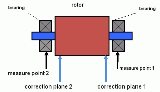
5-ci şəkil. Dinamik balanslaşdırma – düzəliş müstəviləri və ölçmə nöqtələri
Vibrasiya sensorları rulman dayaqlarında 1 və 2 nömrəli nöqtələrdə quraşdırılır. Sürət işarəsi birbaşa rotorun üzərinə bərkidilir, adətən əks etdirici lent yapışdırılır. Sürət işarəsi lazer tahhometri tərəfindən rotorun sürətini və vibrasiya siqnalının fazasını müəyyən etmək üçün istifadə olunur.
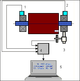
şək. 6. Balanset-1-dən istifadə etməklə iki müstəvidə balanslaşdırma zamanı sensorların quraşdırılması
1,2-vibrasiya sensorları, 3-fazalı, 4-USB ölçmə bloku, 5-noutbuk
Çox hallarda dinamik balanslaşdırma üç start üsulu ilə həyata keçirilir. Bu üsul artıq məlum kütləyə malik test çəkilərinin rotor üzərində 1 və 2-ci müstəvilərdə ardıcıl quraşdırılmasına əsaslanır; beləliklə, kütlələrin və balanslaşdırma çəkilərinin yerləşdirilmə yerinin hesablanması titrəmə parametrlərinin dəyişdirilməsi nəticələrinə əsaslanır.
Ağırlığın quraşdırıldığı yerə düzəliş müstəvisi deyilir. Adətən, düzəliş təyyarələri rotorun quraşdırıldığı rulman dayaqları sahəsində seçilir.
İlkin vibrasiya ilk başlanğıcda ölçülür. Sonra, dayaqlardan birinə yaxın olan rotorda məlum kütlənin sınaq çəkisi quraşdırılır. Sonra ikinci başlanğıc həyata keçirilir və sınaq çəkisinin quraşdırılması səbəbindən dəyişməli olan vibrasiya parametrlərini ölçürük. Sonra birinci müstəvidəki sınaq çəkisi çıxarılır və ikinci müstəvidə quraşdırılır. Üçüncü işə salınma həyata keçirilir və vibrasiya parametrləri ölçülür. Sınaq çəkisi çıxarıldıqda, proqram avtomatik olaraq kütləni və balanslaşdırıcı çəkilərin quraşdırılması yerini (bucaqlarını) hesablayır.
Test çəkilərinin qurulmasında məqsəd sistemin balanssızlıq dəyişikliyinə necə reaksiya verdiyini müəyyən etməkdir. Kütlələri və nümunə çəkilərinin yerini bildiyimiz zaman, proqram məlum disbalansın tətbiqinin vibrasiya parametrlərinə necə təsir etdiyini göstərən sözdə təsir əmsallarını hesablaya bilər. Təsir əmsalları mexaniki sistemin özünün xüsusiyyətləridir və dayaqların sərtliyindən və rotor-dəstək sisteminin kütləsindən (ətalətindən) asılıdır.
Eyni dizaynın eyni tipli mexanizmləri üçün təsir əmsalları oxşar olacaqdır. Siz onları kompüterinizin yaddaşında saxlaya və sonradan sınaq sınaqları keçirmədən eyni tip mexanizmləri balanslaşdırmaq üçün istifadə edə bilərsiniz ki, bu da balanslaşdırmanın işini xeyli yaxşılaşdırır. Həmçinin qeyd etməliyik ki, sınaq çəkilərinin kütləsi elə seçilməlidir ki, sınaq çəkiləri quraşdırılarkən vibrasiya parametrləri nəzərəçarpacaq dərəcədə dəyişsin. Əks halda, təsir əmsallarının hesablanmasında xəta artır və balanslaşdırma keyfiyyəti pisləşir.
Balanset-1 cihazına dair təlimat, balanslaşdırılmış rotorun kütləsindən və fırlanma sürətindən asılı olaraq sınaq çəkisinin kütləsini təxminən təyin edə biləcəyiniz bir düstur təqdim edir. Şəkil 1-dən başa düşdüyünüz kimi, mərkəzdənqaçma qüvvəsi radial istiqamətdə, yəni rotor oxuna perpendikulyar şəkildə təsir göstərir. Buna görə də, vibrasiya sensorları həssaslıq oxunun da radial istiqamətdə olması üçün quraşdırılmalıdır. Adətən, təməlin üfüqi istiqamətdə sərtliyi daha az olur, buna görə də üfüqi istiqamətdə vibrasiya daha yüksək olur. Buna görə də, sensorların həssaslığını artırmaq üçün onların həssaslıq oxunun da üfüqi istiqamətdə olması üçün quraşdırılmalıdır. Baxmayaraq ki, heç bir fundamental fərq yoxdur. Radial istiqamətdəki vibrasiyaya əlavə olaraq, rotorun fırlanma oxu boyunca ox istiqamətində vibrasiyanı idarə etmək lazımdır. Bu vibrasiya adətən balanssızlıqdan deyil, əsasən mufta vasitəsilə birləşdirilmiş valların səhv düzülüşü və səhv düzülüşündən qaynaqlanan digər səbəblərdən yaranır. Bu vibrasiya balanslaşdırma ilə aradan qaldırılmır, bu halda hizalanma tələb olunur. Təcrübədə, adətən, bu cür mexanizmlərdə rotorun balanssızlığı və valların qeyri-bərabər düzülüşü olur ki, bu da titrəmənin aradan qaldırılması işini xeyli çətinləşdirir. Belə hallarda əvvəlcə mexanizmi hizalamalı və sonra balanslaşdırmalısınız. (Güclü fırlanma momenti balanssızlığına baxmayaraq, təməl konstruksiyasının "bükülməsi" səbəbindən ox istiqamətində də titrəmə baş verir).
Ölçmə Dəqiqliyi və Xəta Təhlili
Ölçmə dəqiqliyini başa düşmək peşəkar balanslaşdırma əməliyyatları üçün vacibdir. Balanset-1A aşağıdakı ölçmə dəqiqliyini təmin edir:
| Parametr | Dəqiqlik düsturu | Nümunə (tipik dəyərlər üçün) |
|---|---|---|
| RMS Vibrasiya Sürəti | ±(0,1 + 0,1×Völçülür) mm/san | 5 mm/san üçün: ±0,6 mm/san 10 mm/san üçün: ±1,1 mm/san |
| Fırlanma Tezliyi | ±(1 + 0,005×Nölçülür) rpm | 1000 rpm üçün: ±6 rpm 3000 rpm üçün: ±16 rpm |
| Faza ölçülməsi | ±1° | Bütün sürətlərdə daimi dəqiqlik |
⚠️ Dəqiq balanslaşdırma üçün vacibdir
- !Sınaq çəkisi >20-30% amplituda dəyişikliyinə səbəb olmalıdır və/və ya >20-30° faza dəyişməsi
- !Dəyişikliklər daha kiçik olarsa, ölçmə səhvləri əhəmiyyətli dərəcədə artır
- !Vibrasiya amplitüdü və faza sabitliyi ölçmələr arasında 10-15%-dən çox olmamalıdır
- !Dəyişiklik 15%-dən çox olarsa, rezonans şərtlərini və ya mexaniki problemləri yoxlayın
Balanslaşdırma mexanizmlərinin keyfiyyətinin qiymətləndirilməsi meyarları
Rotorun (mexanizmlərin) balanslaşdırılmasının keyfiyyəti iki yolla qiymətləndirilə bilər. Birinci üsul balanslaşdırma zamanı müəyyən edilmiş qalıq disbalansın dəyərinin qalıq balanssızlığa dözümlülüklə müqayisəsini nəzərdə tutur. Standartda quraşdırılmış müxtəlif sinif rotorlar üçün göstərilən toleranslar ISO 21940-11 «Mechanical vibration – Rotor balancing – Part 11: Procedures and tolerances for rotors with rigid behaviour» (əvvəllər ISO 1940-1).
Bununla belə, bu dözümlülüklərin həyata keçirilməsi minimum vibrasiya səviyyəsinə nail olmaq ilə əlaqəli mexanizmin əməliyyat etibarlılığına tam zəmanət verə bilməz. Bu onunla bağlıdır ki, mexanizmin vibrasiyası təkcə onun rotorunun qalıq balanssızlığı ilə əlaqəli qüvvənin miqdarı ilə deyil, həm də bir sıra digər parametrlərdən də asılıdır: mexanizmin struktur elementlərinin sərtliyi K, onun kütləsi M, sönüm əmsalı və sürət. Buna görə də, mexanizmin dinamik keyfiyyətlərini (o cümlədən onun balansının keyfiyyətini) qiymətləndirmək üçün bəzi hallarda bir sıra standartlarla tənzimlənən mexanizmin qalıq vibrasiya səviyyəsini qiymətləndirmək tövsiyə olunur.
Mexanizmlərin icazə verilən vibrasiya səviyyələrini tənzimləyən ən ümumi standartdır ISO 10816-3:2009 Önizləmə Mexaniki vibrasiya – Fırlanmayan hissələrdə ölçmələrlə maşın vibrasiyasının qiymətləndirilməsi -- Hissə 3: Yerində ölçüldükdə nominal gücü 15 kVt-dan yuxarı və nominal sürəti 120 dövr/dəq ilə 15 000 dövr/dəq arasında olan sənaye maşınları.»
Onun köməyi ilə, elektrik sürücüsünün gücünü nəzərə alaraq, bütün növ maşınlarda tolerantlıq təyin edə bilərsiniz.
Bu universal standarta əlavə olaraq, xüsusi mexanizm növləri üçün hazırlanmış bir sıra ixtisaslaşmış standartlar mövcuddur. Misal üçün,
- ISO 14694:2003 "Sənaye ventilyatorları - Balans keyfiyyəti və vibrasiya səviyyələri üçün spesifikasiyalar""
- ISO 7919-1-2002 "Qarşılıqlı hərəkət olmadan maşınların titrəməsi. Fırlanan vallar üzərində ölçmələr və qiymətləndirmə meyarları. Ümumi rəhbərlik."
🛡️ AB Uyğunluğu üçün Vacib Təhlükəsizlik Mülahizələri
- !Tələb olunan risklərin qiymətləndirilməsi: Balanslaşdırma əməliyyatlarından əvvəl EN ISO 12100 risk qiymətləndirməsini həyata keçirin
- !İxtisaslı Kadrlar: Balanslaşdırma əməliyyatlarını yalnız təlim keçmiş və sertifikatlı işçilər yerinə yetirməlidir
- !Fərdi Qoruyucu Avadanlıqlar: Həmişə EN 166 (gözün qorunması) və EN 352 (eşitmənin qorunması) uyğun PPE-dən istifadə edin
- !Fövqəladə Prosedurlar: Aydın fövqəladə söndürmə prosedurlarını qurun və bütün operatorların onlarla tanış olmasını təmin edin
- !Sənədləşdirmə: İzləmə və uyğunluq üçün bütün balanslaşdırma əməliyyatlarının ətraflı qeydlərini aparın
AB Uyğunluq və Təhlükəsizlik Məlumatı
Uyğunluq Bəyannaməsi
Balanset-1A portativ balans cihazı aşağıdakı Avropa Birliyinin direktiv və standartlarına uyğundur:
| AB Direktivi/Standart | Uyğunluq Təfərrüatları | Təhlükəsizlik Tələbləri |
|---|---|---|
| Maşınlar üzrə Direktiv 2006/42/EC | Maşınlar və təhlükəsizlik komponentləri üçün təhlükəsizlik tələbləri | Riskin qiymətləndirilməsi, təhlükəsizlik təlimatları, CE işarəsi |
| SMM Direktivi 2014/30/EU | Elektromaqnit uyğunluğu tələbləri | Elektromaqnit müdaxiləsinə toxunulmazlıq |
| RoHS Direktivi 2011/65/EU | Təhlükəli maddələrin məhdudlaşdırılması | Qurğuşunsuz, civəsiz, kadmiumsuz komponentlər |
| WEEE Direktivi 2012/19/EU | Elektrik və elektron avadanlıqların tullantıları | Düzgün atma və təkrar emal prosedurları |
| EN ISO 12100:2010 | Maşınların təhlükəsizliyi - Dizayn üçün ümumi prinsiplər | Riskin qiymətləndirilməsi və riskin azaldılması |
| EN 60825-1:2014 | Lazer məhsullarının təhlükəsizliyi - 1-ci hissə | 2-ci sinif lazer təhlükəsizliyi tələbləri |
| EN ISO 14120:2015 | Mühafizəçilər - Ümumi tələblər | Dönən maşın təhlükələrinə qarşı qorunma |
Elektrik Təhlükəsizliyi Standartları
- ✓EN 61010-1: Ölçmə, nəzarət və laboratoriya istifadəsi üçün elektrik avadanlıqları üçün təhlükəsizlik tələbləri
- ✓EN 60950-1: İnformasiya texnologiyaları avadanlığının təhlükəsizliyi (USB ilə işləyən cihaz)
- ✓IEC 61000 seriyası: Elektromaqnit uyğunluğu standartları
- ✓İş gərginliyi: USB vasitəsilə 5V DC (Əlavə Aşağı Gərginlik)
- ✓Enerji istehlakı: < 2,5 Vt
- ✓Mühafizə sinfi: IP54 (tozdan qorunmuş; sıçrayan suya davamlı)
Fırlanan Avadanlıqların Təhlükəsizliyi
⚠️ Məcburi Təhlükəsizlik Prosedurları (EN ISO 12100)
XƏBƏRDARLIQ: Dönən maşınlarla işləyərkən aşağıdakı təhlükəsizlik tələblərinə əməl edin:
- !EN ISO 14118: Gözlənilməz işəsalmanın qarşısının alınması - Sensor quraşdırılmasından əvvəl kilidləmə/etiketləmə prosedurlarından istifadə edin
- !EN ISO 14120: Bütün fırlanan avadanlıqların düzgün şəkildə qorunduğundan əmin olun
- !EN ISO 13857: Fırlanan hissələrdən minimum təhlükəsiz məsafəni qoruyun (bədən üçün 500 mm, barmaqlar üçün 120 mm)
- !Fərdi Qoruyucu Avadanlıqlar: EN 166-ya uyğun olaraq təhlükəsizlik eynəyi, EN 352-yə uyğun olaraq eşitmə qoruyucusu taxın və geniş geyimlərdən çəkinin
- !Hərəkətdə olarkən fırlanan maşınlara heç vaxt sensorlar və ya sınaq çəkiləri quraşdırmayın
- !Sensor quraşdırmadan əvvəl maşının tamamilə dayandığından və təhlükəsiz olduğundan əmin olun
- !Təcili dayanacaq: Operator mövqeyindən 3 metr məsafədə əlçatan olmalıdır
- !Balanslaşdırma əməliyyatlarını yalnız ixtisaslı və sertifikatlı işçilər yerinə yetirməlidir
Lazer Təhlükəsizliyi Təsnifatı
🔴 Sinif 2 Lazer Cihazı (EN 60825-1:2014)
- Dalğa uzunluğu: 650 nm (Qırmızı görünən işıq)
- Maksimum çıxış gücü: < 1 mVt
- Şüa diametri: 100 mm məsafədə 3-5 mm
- Divergensiya: < 1.5 mrad
- Təhlükəsizlik təsnifatı: Göz anlıq məruz qalma üçün təhlükəsizdir (< 0,25 san)
- Tələb olunan etiketləmə: ""LAZER ŞUASİYASI - ŞÜAYA BAXMAYIN - 2-Cİ SİNİF LAZER MƏHSULU""
- Giriş sinfi: Məhdudiyyətsiz (ümumi girişə icazə verilir)
Lazer Təhlükəsizliyi Prosedurları:
- Heç vaxt qəsdən lazer şüasına baxmayın
- Lazeri insanlara, nəqliyyat vasitələrinə və ya təyyarələrə yönəltməyin
- Optik alətlərlə (teleskoplar, durbinlər) lazer şüalarına baxmaqdan çəkinin.
- Parlaq səthlərdən gələn spekulyar əkslərdən xəbərdar olun
- İstifadə etmədiyiniz zaman lazeri söndürün
- Hər hansı bir gözə məruz qalma hadisələrini dərhal bildirin
- Uzun müddət məruz qalma üçün lazer qoruyucu eynəklərdən (650nm-də OD 2+) istifadə edin
Ölçmə Dəqiqliyi və Kalibrləmə
| Parametr | Dəqiqlik | Kalibrləmə Tezliyi |
|---|---|---|
| Vibrasiya amplitudası | ±5% oxu | İllik və ya 1000 saatdan sonra |
| Faza ölçülməsi | ±1° | Hər il |
| Fırlanma sürəti | ±0,1% oxu | Hər il |
| Sensor həssaslığı | 13 mV/(mm/s) ±10% | Sensorları dəyişdirərkən |
Ətraf Mühitə Uyğunluq
- ✓Əməliyyat mühiti: 5°C ilə 50°C arasında, < 85% RH kondensasiyasız
- ✓Saxlama mühiti: -20°C ilə 70°C arasında, < 95% RH kondensasiyasız
- ✓Hündürlük: Dəniz səviyyəsindən 2000 m yüksəkliyə qədər
- ✓Vibrasiya müqaviməti: IEC 60068-2-6 (10-500 Hz, 2g sürətləndirmə)
- ✓Zərbə müqaviməti: IEC 60068-2-27 (15g, 11ms müddət)
- ✓IP reytinqi: IP54 (tozdan qorunmuş; sıçrayan suya davamlı)
Əməliyyat Tələbləri
- ✓Operatorlar AB standartlarına uyğun olaraq maşın təhlükəsizliyi üzrə təlim keçməlidirlər
- ✓İstifadədən əvvəl EN ISO 12100-ə uyğun olaraq riskin qiymətləndirilməsi tələb olunur
- ✓İstehsalçının spesifikasiyasına uyğun olaraq avadanlıqlara qulluq edin
- ✓Hər hansı bir təhlükəsizlik hadisəsi və ya avadanlıq nasazlığı barədə dərhal məlumat verin
- ✓İzləmə üçün bütün balanslaşdırma əməliyyatlarının ətraflı qeydlərini aparın
Sənədləşdirmə Tələbləri
AB uyğunluğu üçün aşağıdakı sənədləri qoruyun:
- ✓EN ISO 12100-ə uyğun risklərin qiymətləndirilməsi sənədləri
- ✓Operator təlimi qeydləri və sertifikatları
- ✓Avadanlığın kalibrlənməsi və texniki xidmət jurnalları
- ✓Əməliyyat qeydlərinin tarixlər, operatorlar və nəticələrlə balanslaşdırılması
- ✓Təhlükəsizlik hadisəsi hesabatları və düzəldici tədbirlər
- ✓Avadanlığın dəyişdirilməsi və ya təmir sənədləri
Texniki Dəstək və Xidmət
Texniki dəstək, kalibrləmə xidmətləri və ehtiyat hissələri üçün:
- ✓İstehsalçı: Vibromera
- ✓Məkan: Narva, Estoniya (Aİ)
- ✓Veb sayt: https://vibromera.eu
- ✓Dəstək dilləri: Bütün əsas dillər. Mətn əsaslı ünsiyyət mövcuddur.
- ✓Xidmətin əhatə dairəsi: Dünya üzrə çatdırılma mövcuddur
- ✓Zəmanət: Satın alındığı tarixdən 12 ay
- ✓Kalibrləmə xidməti: Səlahiyyətli xidmət mərkəzləri vasitəsilə əldə edilə bilər