ব্যালান্সিং সেবা › টার্বাইন & টার্বোচার্জার
টার্বাইন & টার্বোচার্জার ব্যালেন্সিং — চলমান গতিতে স্থানীয়-ভিত্তিক
Steam turbine, gas turbine, hydro runner, wind-turbine main shaft এবং industrial turbocharger rotor এত দ্রুত ঘোরে যে মাইক্রো-গ্রাম মাত্রার eccentricity-ও ধ্বংসাত্মক কম্পন সৃষ্টি করে। আমরা এগুলো ব্যালান্স করি তাদের নিজস্ব বেয়ারিংয়ে, চলমান গতিতে — কোন বিয়োজন নেই, কোন কর্মশালায় পাঠানোর প্রয়োজন নেই — এবং ISO 20816 এবং ISO 21940-11 এর বিপরীতে ফলাফল নথিভুক্ত করুন।
সংক্ষেপে: Turbine এবং industrial turbocharger rotor ব্যালান্স করা হয় স্থানে প্রভাব-সহগ পদ্ধতি ব্যবহার করে চলমান গতিতে। বেয়ারিং হাউসিংয়ে কম্পন সেন্সর এবং লেজার ট্যাকোমিটার প্রশস্ততা এবং দশা পরিমাপ করে; Balanset-1A এক বা দুটি তলের জন্য সঠিক সংশোধন ভর এবং কোণ গণনা করে; ওজন সংযুক্ত করার পরে অবশিষ্ট কম্পন নির্দিষ্ট টার্বাইন শ্রেণীর জন্য ISO 20816 অঞ্চল সীমার বিপরীতে এবং রটরের জন্য ISO 21940-11 G-গ্রেডের বিপরীতে যাচাই করা হয়। সম্পূর্ণ প্রক্রিয়া — প্রথম চলা থেকে নথিভুক্ত ফলাফল পর্যন্ত — সাধারণত সাইটে এক কর্মদিবসের কম সময় লাগে।
আপনার টার্বাইন বা টার্বোচার্জার ভারসাম্যহীন তার লক্ষণ
উচ্চ-গতির টার্বাইন রটর ভারসাম্যহীনতার ফলাফল নাটকীয়ভাবে বৃদ্ধি করে। এই সতর্কতা সংকেতগুলি কখনও উপেক্ষা করা উচিত নয়:
টারবাইন কেন ভারসাম্য হারায় এবং এটির খরচ কত
টারবাইন রোটররা এমন গতিতে কাজ করে যেখানে তারা দৃঢ় ভর নয়, বরং নমনীয় সংস্থা হিসাবে আচরণ করে — তারা নিজস্ব ওজনের অধীনে এবং বায়ুবিদ্যামূলক লোডের অধীনে সামান্য বেঁকে যায়, তাই কার্যকর ভর কেন্দ্র বিভিন্ন মোড জুড়ে পরিবর্তিত হয়। ভারসাম্যহীনতা জমা হয় ব্লেড ক্ষয় এবং জমা বৃদ্ধির মাধ্যমে বাষ্প এবং গ্যাস টারবাইনে, গহ্বরায়ন ক্ষতি জলবিদ্যুৎ চালক চাকায়, বরফ জমা বায়ু-টারবাইন ব্লেডে, এবং সিল ক্ষয় যা ঘূর্ণনশীল ভর পরিবর্তন করে। টারবোচার্জারে, টারবাইন চাকার উপর কার্বন এবং কালি জমা প্রধান কারণ এবং হাজার হাজার অপারেটিং ঘন্টার মধ্যে বিকাশ করতে পারে।
উপেক্ষা করা টারবাইন ভারসাম্যহীনতার খরচ বিয়ারিং প্রতিস্থাপনের বাইরে অনেক দূর পৌঁছায়: ব্লেড ক্লান্তি ব্যর্থতা বর্ধিত ওভারহল জোরপূর্বক করে, সীল ঘর্ষণ নির্ভুলতা পুনঃমেশিনিং প্রয়োজন করে এবং একটি বেস-লোড পাওয়ার প্ল্যান্টে একটি জোরপূর্বক বন্ধ সম্পূর্ণ বার্ষিক রক্ষণাবেক্ষণ বাজেটের গুণিতক খরচ করে। ISO 20816 পরিবারের বিরুদ্ধে ক্ষেত্র কম্পন পরিমাপ অপারেটরদের অবিলম্ব হস্তক্ষেপ এবং ক্রমাগত পর্যবেক্ষণ করা অপারেশনের মধ্যে সিদ্ধান্ত নিতে প্রয়োজনীয় উদ্দেশ্যমূলক ডেটা দেয় — একটি পরিকল্পিত সংশোধন এবং একটি অপরিকল্পিত শাটডাউনের মধ্যে পার্থক্য।
কম্পন অর্ধেক করা কেন বিয়ারিং জীবন বৃদ্ধি করে
আমরা কীভাবে একটি টারবাইন বা টারবোচার্জার ভারসাম্য করি — পদে পদে
Balanset-1A দিয়ে ক্ষেত্র ভারসাম্যকরণ প্রভাব-সহগ পদ্ধতি অনুসরণ করে — একই পদ্ধতি যা আপনি ডিভাইসের সাথে নিজে চালাতে পারেন। টার্বাইনগুলির জন্য নির্ভুলতার প্রয়োজনীয়তা কঠোর এবং নিরাপত্তা প্রোটোকল বেশিরভাগ অন্যান্য রোটরের চেয়ে আরও চাহিদাপূর্ণ:
- বেসলাইন পরিমাপ করুন। কম্পন সেন্সরগুলি বেয়ারিং হাউজিং বা পেডেস্টালে মাউন্ট করা হয়; একটি লেজার ট্যাকোমিটার শ্যাফ্ট ফেজ কোণ ক্যাপচার করে। একটি স্থির-গতি চালান প্রতিটি পরিমাপ সমতলের জন্য কম্পন বিস্তার এবং ফেজ রেকর্ড করে এবং ISO 20816 অঞ্চল অবস্থান স্থাপন করে।
- একটি ট্রায়াল ওজন যোগ করুন। একটি নির্ভুলতা-মেশিনকৃত পরীক্ষা ওজন ভারসাম্যকরণ সমতলে একটি পরিচিত রেডিয়াল অবস্থানে সজ্জিত করা হয় — সাধারণত একটি বোল্ট-সার্কেল গ্রুভ বা ব্লেড-টিপ পকেট। রোটর একই গতিতে আবার চলে যাতে যন্ত্রটি সিস্টেম প্রতিক্রিয়া ক্যাপচার করে।
- ডিভাইসকে গণনা করতে দিন। Balanset-1A প্রভাব-সহগ ম্যাট্রিক্স প্রয়োগ করে প্রতিটি সমতলের জন্য সঠিক সংশোধন ভর এবং কৌণিক অবস্থান নির্ধারণ করতে, রোটর জ্যামিতি যা অনুমতি দেয় তার জন্য সবচেয়ে কঠোর ISO 21940-11 G-গ্রেড লক্ষ্য করে।
- সংশোধন ওজন সজ্জিত করুন। সংশোধন ভর গণনা করা অবস্থানে ইনস্টল করা হয় এবং পরীক্ষা ওজন সরানো হয়। নেট ভর পরিবর্তন OEM ডকুমেন্টেশন এবং ট্রেসেবিলিটির জন্য রেকর্ড করা হয়।
- ISO 20816 এর বিপরীতে যাচাই করুন। চলমান গতিতে একটি চূড়ান্ত চালান প্রশস্তব্যান্ড RMS এবং 1× সিঙ্ক্রোনাস বিস্তার প্রযোজ্য ISO 20816 গ্রহণযোগ্যতা অঞ্চলের মধ্যে রয়েছে তা নিশ্চিত করে। ফলাফলগুলি কাজের রিপোর্টে সংরক্ষিত হয়।
আমরা কী সামঞ্জস্য করি
- শিল্প বাষ্প-টার্বাইন রোটর (পিছন-চাপ এবং ঘনীভবন)
- গ্যাস-টার্বাইন শক্তি বিভাগ এবং কম্প্রেসর চাকা
- জলবিদ্যুৎ Francis, Kaplan এবং Pelton রানার
- বায়ু-টার্বাইন মূল-শ্যাফ্ট সমাবেশ
- Industrial turbocharger turbine এবং compressor wheel (চালনার গতি ≈60 000 RPM পর্যন্ত)
- মাইক্রো-টার্বাইন এবং ORC সম্প্রসারক রোটর
- টার্বো-ব্লোয়ার এবং উচ্চ-গতির কম্প্রেসর ইম্পেলার
- অক্ষীয় এবং রেডিয়াল টার্বাইন পরীক্ষা-রিগ রোটর
সহনশীলতা & মান — ISO 20816 পরিবার
ISO 20816 অ-ঘূর্ণমান অংশগুলির পরিমাপের মাধ্যমে মেশিনের যান্ত্রিক কম্পন মূল্যায়নের জন্য সংজ্ঞায়িত বহু-অংশ মান (বেয়ারিং হাউজিং, পেডেস্টাল)। প্রতিটি অংশ একটি নির্দিষ্ট টার্বাইন শ্রেণীকে কভার করে এবং প্রশস্তব্যান্ড RMS বেগ বা স্থানচলনের জন্য চারটি গুরুত্ব অঞ্চল (A–D) সংজ্ঞায়িত করে:
- ISO 20816-2 — 50 MW এর বেশি ভূমি-ভিত্তিক বাষ্প টার্বাইন এবং জেনারেটর। অঞ্চল A/B থ্রেশহোল্ড সাধারণত 2.3 এবং 4.5 mm/s RMS; অঞ্চল D (ট্রিপ) সাধারণত 7.1 mm/s।
- ISO 20816-4 — 3 MW এর উপরে শক্তি আউটপুট সহ গ্যাস টার্বাইন, শিল্প বায়ু-ডেরিভেটিভ ইউনিট সহ। বেয়ারিং-হাউজিং কম্পন এবং শ্যাফ্ট-আপেক্ষিক স্থানচলনের জন্য আলাদা সীমা নির্ধারণ করে।
- ISO 20816-5 — জলবিদ্যুৎ মেশিন (পাম্প এবং টার্বাইন) বিদ্যুৎ উৎপাদন কেন্দ্রে, Francis, Kaplan এবং Pelton রানার সহ। কম্পন অঞ্চলগুলি জলীয় উত্তেজনা এবং পাশাপাশি যান্ত্রিক ভারসাম্যহীনতা বিবেচনা করে।
- ISO 20816-21 — স্থলভিত্তিক এবং সমুদ্রতীরবর্তী বায়ু টার্বাইন। প্রধান বেয়ারিং, গিয়ারবক্স এবং জেনারেটর কম্পন যা সাধারণ অপারেশন চলাকালীন মূল্যায়ন করা হয়।
সমস্ত টার্বাইন প্রকারের জন্য রোটর ভারসাম্য সহনশীলতা নিয়ন্ত্রিত হয় ISO 21940-11 জি-গ্রেড দ্বারা। উচ্চ-গতির টার্বাইনগুলি সাধারণত প্রয়োজন G 1.0 বা G 2.5. ISO 21940-11 turbocharger-কে তালিকাভুক্ত করে G 6.3 তার সাধারণ rotor উদাহরণগুলোর মধ্যে এবং G-grade calculation framework প্রদান করে; নির্দিষ্ট turbocharger tolerance সাধারণত OEM দ্বারা নির্ধারিত হয় এবং সাধারণ ISO উদাহরণের তুলনায় আরও কঠোর হতে পারে। আমাদের Balanset-1A measurement আপনাকে একক সাইট সেশনে ISO 20816-এর vibration acceptance limit এবং ISO 21940-11-এর residual-unbalance limit - উভয়ের সাথেই সামঞ্জস্য প্রদর্শনের জন্য প্রয়োজনীয় ডেটা দেয়।
ব্লেড-অনুরণন নিরাপত্তার জন্য, সমালোচনামূলক-গতি ক্রসিং ম্যাপ করা হয় Campbell ডায়াগ্রাম পদ্ধতি ব্যবহার করে; আমাদের টার্বাইন ব্লেড ফ্রিকোয়েন্সি ক্যালকুলেটর আপনাকে চেক করতে দেয় যে কমিশনিং বা পুনঃব্লেডিংয়ের আগে কোনও ব্লেড প্রাকৃতিক ফ্রিকোয়েন্সি অপারেটিং গতির পরিসরের মধ্যে পড়ে কিনা।
Balanset-1A — টার্বাইনের জন্য আপনার সম্পূর্ণ অন-সাইট ভারসাম্য কিট
এই পৃষ্ঠায় সবকিছু একটি পোর্টেবল যন্ত্র দিয়ে করা হয়েছে: Balanset-1A। এটি একটি দ্বি-চ্যানেল গতিশীল ভারসাম্যকারী এবং কম্পন বিশ্লেষক যা টার্বাইন এবং টার্বোচার্জার রোটর ভারসাম্য রাখে তাদের নিজস্ব বেয়ারিংয়ে, অপারেটিং গতিতে, 3-run influence-coefficient method ব্যবহার করে — সফটওয়্যারটি সঠিক correction mass ও angle গণনা করে এবং একটি report সংরক্ষণ করে। এর vibration channel 5–1000 Hz কভার করে, যা আনুমানিক 1× running speed 300–60 000 RPM-এর সমতুল্য (সেরা নির্ভুলতা ≈33 000 RPM / 550 Hz পর্যন্ত); 100 000–300 000 RPM-এ ঘূর্ণায়মান automotive-style turbocharger wheel এই সীমার বাইরে এবং এর জন্য বিশেষায়িত high-speed balancing equipment প্রয়োজন।
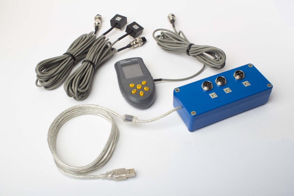
সম্পূর্ণ কিটে কী আছে
€1,975 · সম্পূর্ণ কিট, স্টকে উপলব্ধ, VAT চালান
- ইন্টারফেস পরিমাপ ইউনিট (USB, 2 চ্যানেল)
- দুটি ভাইব্রেশন অ্যাক্সিলারোমিটার (4 মি ক্যাবল, 10 মি ঐচ্ছিক)
- লেজার ট্যাকোমিটার / অপটিক্যাল ফেজ সেন্সর (50–500 mm)
- সেন্সরের জন্য চৌম্বকীয় দাঁড়ানো
- ট্রায়াল & সংশোধন ওজনের জন্য ডিজিটাল স্কেল
- Windows ব্যালান্সিং এবং বিশ্লেষণ সফটওয়্যার
- প্লাস্টিক পরিবহন কেস
ফুল কিট
ইউনিট · ২টি সেন্সর · লেজার ট্যাকোমিটার · ম্যাগনেটিক স্ট্যান্ড · ডিজিটাল স্কেল · সফটওয়্যার · ট্রান্সপোর্ট কেস। টারবাইন ব্যালেন্সিং শুরু করার জন্য বক্স থেকে বের করেই যা যা প্রয়োজন, সব কিছু।
OEM সেট
ইউনিট · 2 সেন্সর · লেজার ট্যাকোমিটার · সফটওয়্যার। ইন্টিগ্রেটরদের জন্য যাদের ইতিমধ্যে একটি স্ট্যান্ড, স্কেল এবং কেস রয়েছে, বা যারা ইউনিটকে একটি ব্যালেন্সিং মেশিনে এম্বেড করে।
| প্যারামিটার | মান |
|---|---|
| পরিমাপ চ্যানেল | 2 (সিঙ্গেল- এবং টু-প্লেন ব্যালান্সিং) |
| ভাইব্রেশন বেগ পরিসীমা | 0.2–80 mm/s RMS |
| ফ্রিকোয়েন্সি পরিসীমা | 5–1000 Hz (550 Hz-এর উপরে ≤10% amplitude error) |
| পরিমাপ নির্ভুলতা | ±5% of full scale |
| পদ্ধতি | 3-রান প্রভাব-সহগুণ (1 বা 2 প্লেন) |
| বিশ্লেষণ | 1× এ প্রশস্ততা ও ফেজ, FFT বর্ণালী ও তরঙ্গরূপ, সংরক্ষিত প্রতিবেদন |
| ল্যাপটপ | অন্তর্ভুক্ত নয় (Windows PC, অনুরোধের উপর উপলব্ধ) |
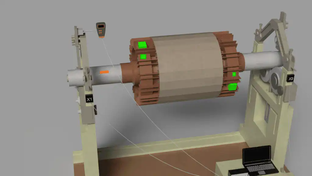
অন-সাইট টার্বাইন এবং টার্বোচার্জার ভারসাম্য
ভারসাম্য সেটআপে রোটর
Balanset-1A-এর সাথে দ্বি-সংশোধন-তল অন-সাইট ভারসাম্যের জন্য যন্ত্রযুক্ত একটি উচ্চ-গতির টার্বো রোটর।
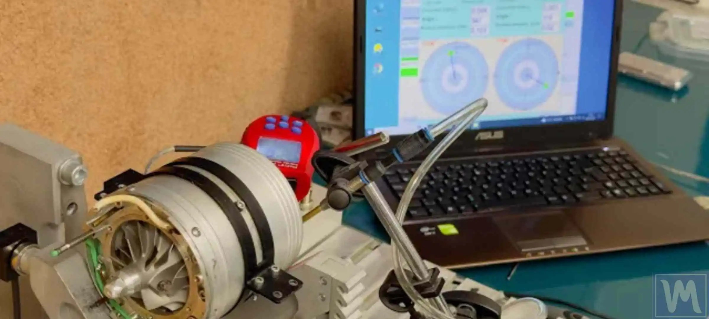
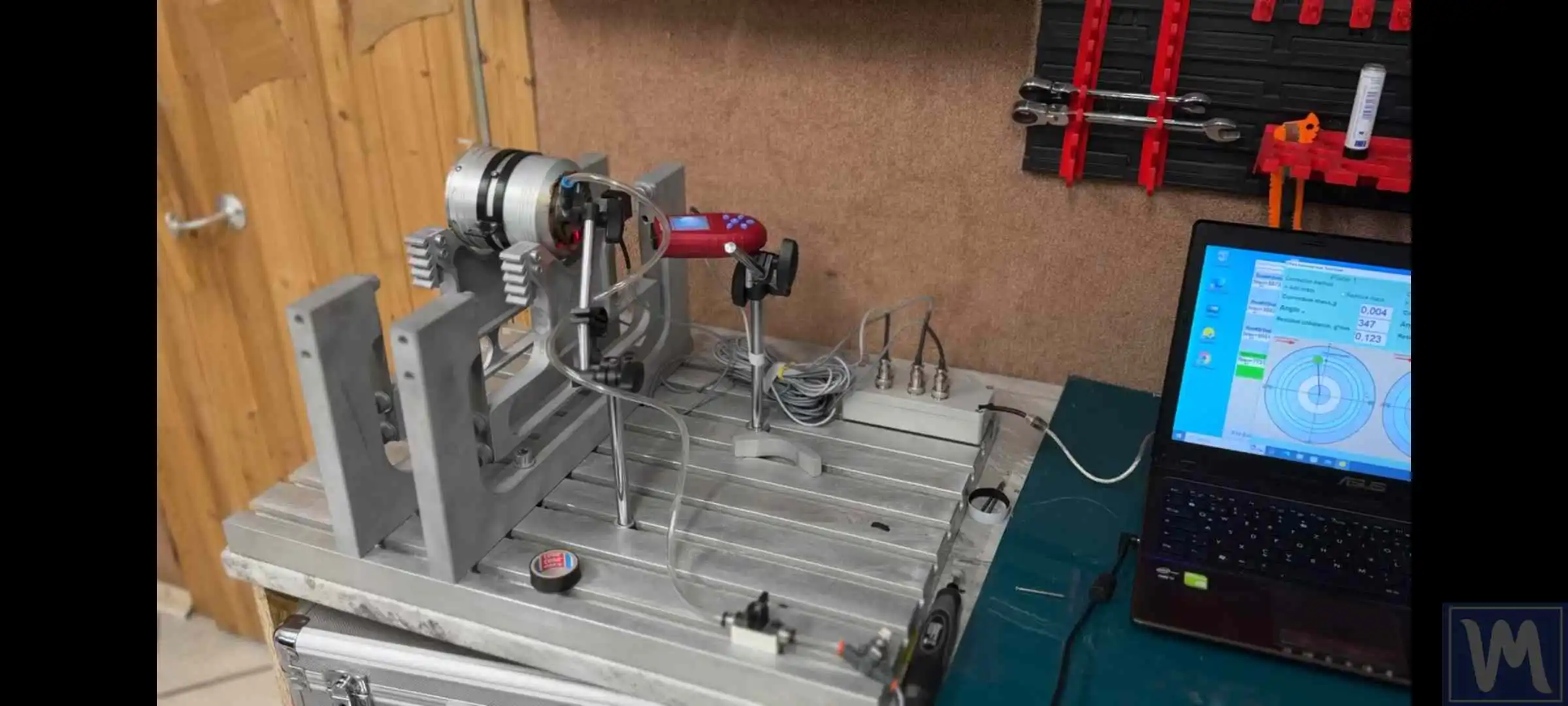
বেয়ারিংয়ে কম্পন পরিমাপ
সেন্সর এবং লেজার ট্যাকো বেয়ারিংয়ে 1× প্রশস্ততা এবং চলমান গতিতে ফেজ ক্যাপচার করে।
ক্ষেত্র ব্যালেন্সিং বনাম ব্যালেন্সিং যন্ত্র — কোনটি সঠিক?
| মানদণ্ড | ক্ষেত্র সামঞ্জস্য (Balanset-1A) | কর্মশালা ভারসাম্য মেশিন |
|---|---|---|
| রোটর অপসারণ প্রয়োজন | না — স্থানে ভারসাম্য করা হয়েছে | হ্যাঁ — সম্পূর্ণ বিয়োগ |
| প্রকৃত অপারেটিং অবস্থা | হ্যাঁ — প্রকৃত গতি, প্রকৃত বিয়ারিং | না — নিম্ন গতি, ভিন্ন সমর্থন |
| ডাউনটাইম | এক শিফট পর্যন্ত ঘন্টা | দিন থেকে সপ্তাহ |
| নমনীয় রোটর প্রভাব সংগৃহীত | হ্যাঁ — গতিতে বেঁকানো অন্তর্ভুক্ত | নিম্ন গতির দোকান চালুতে নয় |
| ISO 20816 কম্পন যাচাইকরণ | পদ্ধতিতে নির্মিত | পুনঃসমাবেশের পরে পৃথক ধাপ |
| দ্বি-তলীয় সংশোধন | হ্যাঁ (উভয় সংশোধন সমতল একযোগে) | হ্যাঁ |
| পোর্টেবল — যেকোনো সাইট | হ্যাঁ — ক্যারি কেসে ফিট করে | শুধুমাত্র নির্দিষ্ট কর্মশালা |
| প্রতি কাজের সাধারণ খরচ | কম (পরিবহন নেই, ক্রেন নেই) | বেশি (লজিস্টিক + দোকানের সময়) |
বিনামূল্যে টার্বাইন ক্যালকুলেটর
টারবাইন সমতা (ব্যালান্সিং) FAQ
একটি টারবাইন রোটর ক্ষেত্রে সমতাবদ্ধ করা যায় বা এটি একটি সমতা মেশিন প্রয়োজন?
কোন ISO 20816 অংশ আমার টারবাইনে প্রযোজ্য?
একটি টার্বোচার্জারের জন্য কোন ভারসাম্য গ্রেড প্রয়োজন?
আমার টারবাইন প্রতিটি প্রধান ওভারহলের পরে অতিরিক্ত কম্পনে চলে যায় — কেন?
Balanset-1A কি ISO 20816-এ বেয়ারিং-হাউসিং কম্পন পরিমাপ করতে পারে?
আমি কিভাবে জানব এক বিমানে বা দুই বিমানে ভারসাম্য করব কিনা?
তত্ত্ব শিখুন
আপনার টারবাইন মূল্যায়ন এবং ভারসাম্য — ISO মান অনুযায়ী
Balanset-1A ISO 20816-এ বেয়ারিং-হাউসিং কম্পন পরিমাপ করে এবং ISO 21940-11-এ দ্বি-বিমান ক্ষেত্র ভারসাম্য সম্পাদন করে — আপনাকে একটি একক বহনযোগ্য যন্ত্রে রোগ নির্ণয় এবং সংশোধন উভয়ই প্রদান করে, প্রতিটি কাজের জন্য একটি নথিভুক্ত ফলাফল সহ।