
מאזן נייד ""איזון-1A""
מערכת איזון דינמית מבוססת מחשב דו-ערוצית
מדריך הפעלה
לְהַאִיץ. 1.56 במאי 2023
2023 | פורטוגל, פורטו
הודעת בטיחות: מכשיר זה עומד בתקני הבטיחות של האיחוד האירופי. מוצר לייזר Class 2. יש לפעול לפי נהלי הבטיחות של ציוד מסתובב. ראה מידע בטיחות מלא למטה →
1. סקירת מערכת איזון
Balanset-1A איזון מספקת שירותי איזון דינמי חד-מישורי ודו-מישורי עבור מאווררים, גלגלי השחזה, צירים, מכונות ריסוק, משאבות ומכונות מסתובבות אחרות.
מאזן Balanset-1A כולל שני חיישני ויברציה (מדי תאוצה), חיישן פאזה לייזר (טכומטר), יחידת ממשק USB דו-ערוצית עם קדם-מגברים, אינטגרטורים ומודול רכישת ADC ותוכנת איזון מבוססת Windows. Balanset-1A דורש מחשב נייד או מחשב אחר תואם Windows (WinXP...Win11, 32 או 64 סיביות).
תוכנת איזון מספקת את פתרון האיזון הנכון לאיזון חד מישור ושני מישור אוטומטי. Balanset-1A הוא פשוט לשימוש עבור מומחים ללא רטט.
כל תוצאות האיזון נשמרות בארכיון וניתן להשתמש בהן ליצירת הדוחות.
תכונות עיקריות
קל לשימוש
- • מסת ניסוי לבחירת המשתמש
- • חלון קופץ לתקפות המונית של ניסוי
- • הזנת נתונים ידנית
יכולות מדידה
- • סל"ד, אמפליטודה ופאזה
- • ניתוח ספקטרום FFT
- • תצוגת צורת גל וספקטרום
- • נתונים דו-ערוציים בו-זמניים
פונקציות מתקדמות
- • מקדמי השפעה שנשמרו
- • איזון גימור
- • חישוב אקסצנטריות של המנדרל.
- • חישוב סובלנות ISO 1940.
ניהול נתונים
- • אחסון נתונים בלתי מוגבל לאיזון
- • אחסון צורת גל של רטט
- • ארכיון ודוחות
כלי חישוב
- • חישוב משקל מפוצל
- • חישוב קידוח
- • שינוי מישורי תיקון
- • ויזואליזציה של גרף פולארי
אפשרויות ניתוח
- • הסר או השאר משקולות ניסיון
- • תרשימי RunDown (ניסיוניים)
2. מפרט
| פָּרָמֶטֶר | מִפרָט |
|---|---|
| טווח מדידה של ערך הבסיס-ממוצע הריבוע (RMS) של מהירות הרטט, מ"מ/שנייה (עבור רטט פי 1) | מ-0.02 עד 100 |
| טווח התדרים של מדידת RMS של מהירות הרטט, הרץ | מ-5 עד 550 |
| מספר מישורי התיקון | 1 או 2 |
| טווח תדירות מדידת הסיבוב, סל"ד | 100 – 100000 |
| טווח מדידת שלב הרטט, מעלות זווית | מ-0 עד 360 |
| שגיאה במדידת שלב הרטט, מעלות זוויתית | ± 1 |
| דיוק מדידה של מהירות רטט RMS | ±(0.1 + 0.1×Vנמדד) מ"מ/שנייה |
| דיוק המדידה של תדר הסיבוב | ±(1 + 0.005×Nנמדד) סל"ד |
| זמן ממוצע בין תקלות (MTBF), שעות, דקות | 1000 |
| אורך חיים ממוצע, שנים, דקות | 6 |
| מידות (במארז קשיח), ס"מ | 39*33*13 |
| מסה, ק"ג | <5 |
| מידות כוללות של חיישן הוויברטור, מ"מ, מקסימום | 25*25*20 |
| מסת חיישן הוויברטור, ק"ג, מקסימום | 0.04 |
|
תנאי הפעלה: טווח טמפרטורות: מ-5°C עד 50°C - לחות יחסית: < 85%, בלתי רווי - ללא שדה חשמלי-מגנטי חזק ופגיעה חזקה |
|
3. חבילה
מאזן Balanset-1A כולל שני מדי תאוצה בעלי ציר יחיד, סמן לייזר לפאזה (טכומטר דיגיטלי), יחידת ממשק USB דו-ערוצית עם קדם-מגברים, אינטגרטורים ומודול רכישת ADC ותוכנת איזון מבוססת Windows.
ערכת משלוח
| תיאור | מספר | הערה |
|---|---|---|
| יחידת ממשק USB | 1 | |
| סמן התייחסות פאזה בלייזר (טכומטר) | 1 | |
| מדי תאוצה חד-ציריים | 2 | |
| מעמד מגנטי | 1 | |
| מאזניים דיגיטליים | 1 | |
| מארז קשיח להובלה | 1 | |
| ""באלאנסט-1A". מדריך למשתמש. | 1 | |
| דיסק פלאש עם תוכנת איזון | 1 |
4. BALANCE PRINCIPLES
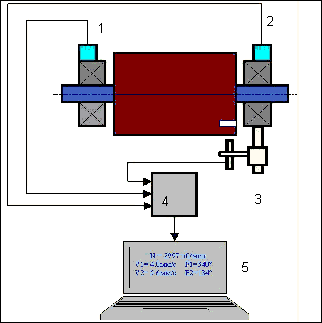
4.1. ""Balanset-1A" כולל (איור 4.1) יחידת ממשק USB (1)שני מדי תאוצה (2) and (3), סמן ייחוס פאזה (4) ומחשב נייד (לא כלול) (5).
ערכת המשלוח כוללת גם את המעמד המגנטי (6) משמש להרכבת סמן ייחוס פאזה ומשקלים דיגיטליים 7.
X1 and X2 connectors intended for connection of the vibration sensors respectively to 1 and 2 measuring channels, and the X3 connector used for connection of the phase reference marker.
The USB cable provides power supply and connection of the USB interface unit to the computer.

איור 4.1. ערכת משלוח של "Balanset-1A""
תנודות מכניות גורמות לאות חשמלי פרופורציונלי לתאוצת הרטט ביציאה של חיישן הרטט. אותות דיגיטליים ממודול ADC מועברים דרך USB למחשב הנייד. (5). סמן ייחוס פאזה מייצר את אות הפולס המשמש לחישוב תדר הסיבוב וזווית הפאזה של הרטט. תוכנה מבוססת Windows מספקת פתרון לאיזון במישור יחיד ובמישור דו-מישורי, ניתוח ספקטרום, תרשימים, דוחות, אחסון מקדמי השפעה.
5. SAFETY PRECAUTIONS
⚡ שימו לב - בטיחות חשמלית
5.1. When operating on 220V electrical safety regulations must be observed. It is not allowed to repair the device when connected to 220 V.
5.2. אם אתם משתמשים במכשיר בסביבה עם מתח AC באיכות נמוכה או בנוכחות הפרעות רשת, מומלץ להשתמש בכוח עצמאי מחבילת הסוללות של המחשב.
⚠️ דרישות בטיחות נוספות לציוד מסתובב
- !נעילת מכונה: יש ליישם תמיד נהלי נעילה/תיוג נכונים לפני התקנת חיישנים
- !ציוד מגן אישי: יש ללבוש משקפי מגן, הגנה על השמיעה ולהימנע מבגדים רחבים ליד מכונות מסתובבות
- !התקנה מאובטחת: ודאו שכל החיישנים והכבלים מחוברים היטב ושאינם נלכדים בחלקים מסתובבים
- !נהלי חירום: דעו את מיקום עצירות החירום ונהלי הכיבוי
- !הַדְרָכָה: רק אנשי צוות מיומנים צריכים להפעיל ציוד איזון על מכונות מסתובבות
6. הגדרות תוכנה וחומרה
6.1. USB drivers and balancing software installation
Before working install drivers and balancing software.
רשימת תיקיות וקבצים
Installation disk (flash drive) contains the following files and folders:
- Bs1Av###Setup – תיקייה עם תוכנת האיזון "Balanset-1A" (### – מספר גרסה)
- ארד דרייב – דרייברים של USB
- מדריך_אימון_אלקטרוני.pdf – מדריך זה
- Bal1Av###Setup.exe – קובץ התקנה. קובץ זה מכיל את כל הקבצים והתיקיות המאוחסנים בארכיון שהוזכרו לעיל. ### – גרסה של תוכנת "Balanset-1A".
- Ebalanc.cfg – ערך רגישות
- בל.יני – נתוני אתחול מסוימים
הליך התקנת התוכנה
For installing drivers and specialized software run file Bal1Av###Setup.exe and follow setup instructions by pressing buttons «Next», «ОК» etc.
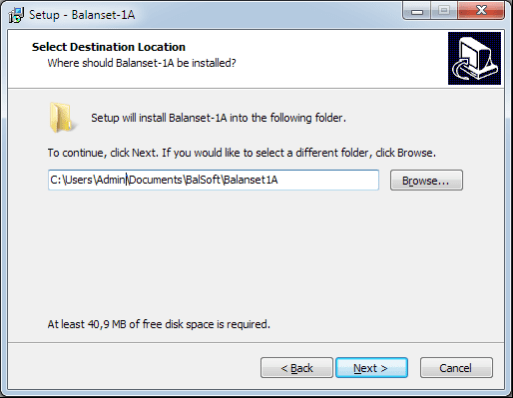
Choose setup folder. Usually the given folder should not be changed.
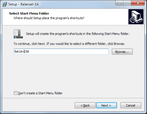
Then the program requires specifying Program group and desktop folders. Press button Next.
סיום ההתקנה
- ✓Install sensors on the inspected or balanced mechanism (Detailed information about how to install the sensors is given in Annex 1)
- ✓Connect vibration sensors 2 and 3 to the inputs X1 and X2, and phase angle sensor to the input X3 of USB interface unit.
- ✓Connect USB interface unit to the USB-port of the computer.
- ✓בעת שימוש בספק כוח AC, חבר את המחשב לרשת החשמל. חבר את ספק הכוח ל-220 וולט, 50 הרץ.
- ✓לחץ על קיצור הדרך "Balanset-1A" בשולחן העבודה.
7. תוכנת איזון
7.1. כללי
Initial window
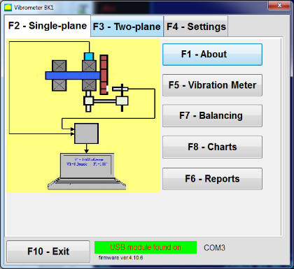
בעת הפעלת התוכנית "Balanset-1A" מופיע חלון ההתחלתי, המוצג באיור 7.1.

איור 7.1. חלון התחלתי של "Balanset-1A""
ישנם 9 כפתורים בחלון ההתחלתי עם שמות הפונקציות המתקבלות בעת לחיצה עליהם.
F1-«About»
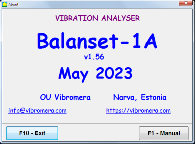
איור 7.2. חלון F1-«אודות»
F2-«Single plane», F3-«Two plane»
לחיצה על ""F2- מישור יחיד"" (או F2 מקש פונקציה במקלדת המחשב) בוחר את רטט המדידה בערוץ X1.
After clicking this button, the computer display diagram shown in Fig. 7.1 illustrating a process of measuring the vibration only on the first measuring channel (or the balancing process in a single plane).
לחיצה על ה""F3-דו-מישורי"" (או F3 function key on the computer keyboard) selects the mode of vibration measurements on two channels X1 and X2 simultaneously. (Fig. 7.3.)
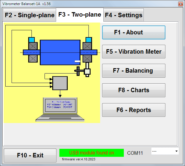
איור 7.3. חלון התחלתי של "Balanset-1A". איזון דו-מישורי.
F4 – «הגדרות»
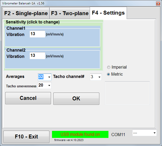
איור 7.4. חלון "הגדרות"
In this window you can change some Balanset-1A settings.
- Sensitivity. The nominal value is 13 mV / mm/s.
Changing the sensitivity coefficients of sensors is required only when replacing sensors!
תשומת הלב!
כאשר מזינים מקדם רגישות, החלק השברי שלו מופרד מהחלק השלם באמצעות נקודה עשרונית (הסימן ",").
- Averaging - מספר ממוצעים (מספר סיבובי הרוטור שבאמצעותם מחושבים הנתונים לדיוק רב יותר)
- Tacho channel# - ערוץ # הטאצ'ו מחובר. כברירת מחדל - ערוץ שלישי.
- Unevenness - הפרש משך הזמן בין פולסי טכומטר סמוכים, אשר לעיל נותן את האזהרה ""Failure of the tachometer"
- Imperial/Metric - בחר את מערכת היחידות.
Com port number is assigned automatically.
F5 – «מד רעידות»
Pressing this button (or a function key of F5 (במקלדת המחשב) מפעיל את מצב מדידת הרטט בערוץ מדידה אחד או שניים של מד הרטט הווירטואלי בהתאם למצב הכפתורים ""F2"-מישור יחיד", ""F3"דו-מישורי".
F6 – «דוחות»
Pressing this button (or F6 function key on the computer keyboard) switches on the balancing Archive, from which you can print the report with the results of balancing for a specific mechanism (rotor).
F7 - "איזון"
לחיצה על כפתור זה (או על מקש הפונקציה F7 במקלדת) מפעילה מצב איזון במישורי תיקון אחד או שניים, בהתאם למצב המדידה שנבחר על ידי לחיצה על הכפתורים ""F2"-מישור יחיד", ""F3"דו-מישורי".
F8 - "תרשימים"
Pressing this button (or F8 מקש פונקציה במקלדת המחשב) מאפשר מד רטט גרפי, אשר יישומו מוצג על גבי תצוגה בו זמנית עם הערכים הדיגיטליים של האמפליטודה והפאזה של הרטט הגרפי של פונקציית הזמן שלו.
F10 – «יציאה»
Pressing this button (or F10 מקש הפונקציה במקלדת המחשב) משלים את התוכנית "Balanset-1A".
7.2. "מד רעידות""
לפני העבודה ב""Vibration meter"במצב ", התקן חיישני רטט על המכונה וחבר אותם בהתאמה למחברים X1 ו-X2 של יחידת ממשק ה-USB. יש לחבר את חיישן הטכומטר לקלט X3 של יחידת ממשק ה-USB.

Fig. 7.5 USB interface unit
הניחו סרט מחזיר אור על פני הרוטור לעבודה עם טכומטר.

איור 7.6. סרט מחזיר אור.
Recommendations for the installation and configuration of sensors are given in Annex 1.
כדי להתחיל את המדידה במצב מד הרטט, לחצו על הכפתור ""F5 – Vibration Meter"" בחלון ההתחלתי של התוכנית (ראה איור 7.1).
Vibration Meter window appears (see. Fig.7.7)

Fig. 7.7. Vibration meter mode. Wave and Spectrum.
כדי להתחיל במדידות רטט לחץ על כפתור ""F9 – רוץ"" (או לחץ על מקש הפונקציה F9 on the keyboard).
If מצב טריגר אוטומטי מסומן - תוצאות מדידות הרטט יוצגו מעת לעת על המסך.
במקרה של מדידה סימולטנית של רעידות בערוץ הראשון והשני, החלונות הממוקמים מתחת למילים ""Plane 1"" ו""Plane 2""יתמלא.
מדידת רעידות במצב "רעידות" יכולה להתבצע גם עם חיישן זווית פאזה מנותק. בחלון ההתחלתי של התוכנית, ערך הרעידות הכוללת של RMS (V1s, V2s) will only be displayed.
ישנן ההגדרות הבאות במצב מד רטט
- RMS נמוך, הרץ - התדר הנמוך ביותר לחישוב RMS של הרטט הכולל
- רוחב פס - רוחב פס של תדר הרטט בטבלה
- Averages - מספר ממוצעים לדיוק מדידה רב יותר
כדי להשלים את העבודה במצב "מד רטט" לחץ על הכפתור ""F10 – Exit""ולחזור לחלון ההתחלתי.

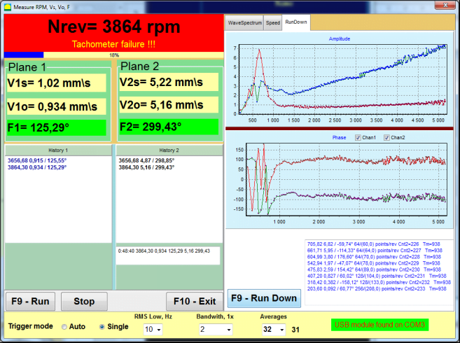
Fig. 7.8. Vibration meter mode. Rotation speed Unevenness, 1x vibration wave form.
Fig. 7.9. Vibration meter mode. Rundown (beta version, no warranty!).
7.3 הליך איזון
Balancing is performed for mechanisms in good technical condition and correctly mounted. Otherwise, before the balancing the mechanism must be repaired, installed in proper bearings and fixed. Rotor should be cleaned of contaminants that can hinder from balancing procedure.
Before balancing measure vibration in Vibration meter mode (F5 button) to be sure that mainly vibration is 1x vibration.
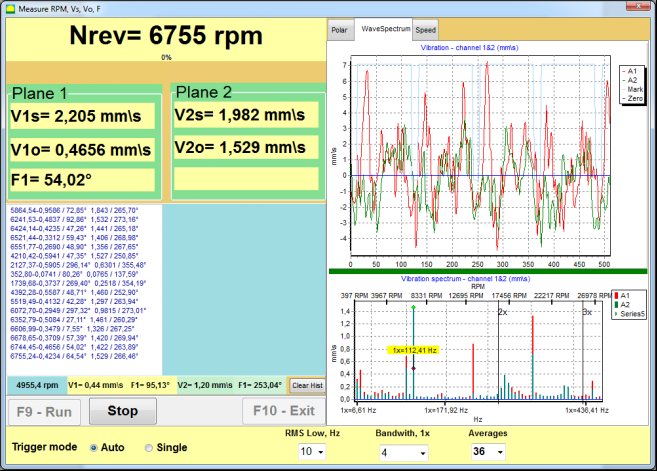
Fig. 7.10. Vibration meter mode. Checking overall (V1s,V2s) and 1x (V1o,V2o) vibration.
אם ערך הוויברציה הכוללת V1s (V2s) שווה בקירוב לגודל הוויברציה בתדר הסיבוב (וויברציה כפולה) V1o (V2o), ניתן להניח שהתרומה העיקרית למנגנון הוויברציה נובעת מחוסר איזון של הרוטור. אם ערך הוויברציה הכוללת V1s (V2s) גבוה בהרבה מרכיב הוויברציה כפולה V1o (V2o), מומלץ לבדוק את מצב המנגנון - מצב המסבים, הרכבתו על הבסיס, וידוא שאין מגע בין החלקים הקבועים לרוטור במהלך הסיבוב וכו'.
כמו כן, יש לשים לב ליציבות הערכים הנמדדים במצב מד רטט - אמפליטודה ומופע הרטט לא צריכות להשתנות ביותר מ-10-15% בתהליך המדידה. אחרת, ניתן להניח שהמנגנון פועל באזור הקרוב לתהודה. במקרה זה, יש לשנות את מהירות הסיבוב של הרוטור, ואם זה לא אפשרי - יש לשנות את תנאי התקנת המכונה על היסודות (לדוגמה, יש להרכיב אותה באופן זמני על תומכי קפיץ).
לאיזון הרוטור שיטת מקדם ההשפעה יש להשתמש באיזון (שיטת 3 ריצות).
Trial runs are done to determine the effect of trial mass on vibration change, mass and place (angle) of installation of correction weights.
First determine the original vibration of a mechanism (first start without weight), and then set the trial weight to the first plane and made the second start. Then, remove the trial weight from the first plane, set in a second plane and made the second start.
The program then calculates and indicates on the screen the weight and location (angle) of installation of correction weights.
When balancing in a single plane (static), the second start is not required.
Trial weight is set to an arbitrary location on the rotor where it is convenient, and then the actual radius is entered in the setup program.
(Position Radius is used only for calculating the unbalance amount in grams * mm)
חָשׁוּב!
- Measurements should be carried out with the constant speed of rotation of the mechanism!
- Correction weights must be installed on the same radius as the trial weights!
מסת משקולת הניסיון נבחרת כך שלאחר שלב ההתקנה שלה (> 20-30°) ו-(20-30%) משרעת הרטט משתנה באופן משמעותי. אם השינויים קטנים מדי, השגיאה תגדל מאוד בחישובים הבאים. יש למקם את מסת הניסיון בצורה נוחה באותו מקום (באותה זווית) כמו סימן הפאזה.
נוסחת חישוב מסת משקל ניסיון
Mt = Mr × Ksupport × Kvibration / (Rt × (N/100)²)
אֵיפֹה:
- הר - מסת משקל ניסיון, גרם
- מַר - מסת הרוטור, g
- Ksupport - מקדם קשיחות התמיכה (1-5)
- קוויברציה - מקדם רמת רעידות (0.5-2.5)
- רט - רדיוס התקנה של משקל ניסיון, ס"מ
- נ - מהירות הרוטור, סל"ד
מקדם קשיחות התמיכה (Ksupport):
- 1.0 - תומכים רכים מאוד (בולמי גומי)
- 2.0-3.0 - קשיחות בינונית (מיסבים סטנדרטיים)
- 4.0-5.0 - תמיכות קשיחות (יסוד מסיבי)
מקדם רמת הרטט (Kvibration):
- 0.5 - רטט נמוך (עד 5 מ"מ/שנייה)
- 1.0 - רטט רגיל (5-10 מ"מ/שנייה)
- 1.5 - רטט מוגבר (10-20 מ"מ/שנייה)
- 2.0 - רעידות גבוהות (20-40 מ"מ/שנייה)
- 2.5 - רעידות גבוהות מאוד (>40 מ"מ/שנייה)
🔗 השתמשו במחשבון המקוון שלנו:
מחשבון משקל ניסיון →⚠️ חשוב!
After each test run trial mass are removed! Correction weights set at an angle calculated from the place of trial weight installation in the direction of rotation of the rotor!
הסבר על חישוב הזווית:
זווית ההתקנה של משקל התיקון היא תמיד נמדד מנקודת התקנת משקל הניסוי בכיוון סיבוב הרוטור.
- נקודת האפס (0°): המיקום המדויק שבו התקנת את משקולת הניסיון הופך לנקודת הייחוס שלך (0 מעלות).
- כיוון: מדוד את הזווית באותו כיוון שבו מסתובב הרוטור.
דוגמה: אם הרוטור מסתובב בכיוון השעון, מדוד את הזווית בכיוון השעון ממיקום משקל הניסוי. - פֵּשֶׁר: אם התוכנית מציגה זווית של 120°, עליך להתקין את משקל התיקון 120 מעלות קדימה של מיקום משקל הניסיון בכיוון הסיבוב.
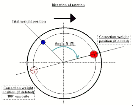
Fig. 7.11. Correction weight mounting.
מוּמלָץ!
לפני ביצוע איזון דינמי, מומלץ לוודא שחוסר האיזון הסטטי אינו גבוה מדי. עבור רוטורים בעלי ציר אופקי, ניתן לסובב את הרוטור ידנית בזווית של 90 מעלות מהמיקום הנוכחי. אם הרוטור אינו מאוזן סטטית, הוא יסתובב למצב שיווי משקל. לאחר שהרוטור מגיע למצב שיווי משקל, יש צורך להתקין את משקולת האיזון בנקודה העליונה, בערך בחלק האמצעי של אורך הרוטור. יש לבחור את המשקולת באופן כזה שהרוטור לא יזוז בשום מיקום.
איזון מקדים כזה יפחית את כמות הרטט בהתחלה הראשונה של רוטור לא מאוזן מאוד.
התקנה והרכבה של חיישן
Vibration sensor must be installed on the machine in the selected measuring point and connected to the input X1 of the USB interface unit.
ישנן שתי תצורות הרכבה:
- מגנטים
- Threaded studs M4
Optical tacho sensor should be connected to the input X3 of the USB interface unit. Furthermore, for use of this sensor a special reflecting mark should be applied on surface of a rotor.
דרישות התקנה של חיישן אופטי
- ✓מרחק לפני השטח של הרוטור: 50-500 מ"מ (בהתאם לדגם החיישן)
- ✓רוחב סרט מחזיר אור: מינימום 1-1.5 ס"מ (תלוי במהירות וברדיוס)
- ✓הִתמַצְאוּת: ניצב לפני השטח של הרוטור
- ✓הַרכָּבָה: השתמש במעמד מגנטי או מהדק למיקום יציב
- ✓הימנעו מאור שמש ישיר או תאורה מלאכותית בהירה על חיישן/קלטת
💡 חישוב רוחב הסרט: לקבלת ביצועים אופטימליים, חשב את רוחב הסרט באמצעות:
L ≥ (N × R)/30000 ≥ 1.0-1.5 ס"מ
כאשר: L - רוחב הסרט (ס"מ), N - מהירות הרוטור (סל"ד), R - רדיוס הסרט (ס"מ)
Detailed requirements on site selection of the sensors and their attachment to the object when balancing are set out in Annex 1.
7.4 איזון במישור יחיד
איור 7.12. "איזון במישור יחיד"
ארכיון איזון
כדי להתחיל לעבוד על התוכנית ב""Single-Plane balancing"במצב ", לחץ על""F2-Single-plane"" (או לחץ על מקש F2 במקלדת המחשב).
לאחר מכן לחצו על ה""F7 – Balancing"כפתור ", ולאחר מכן Single Plane balancing archive window will appear, in which the balancing data will be saved (see Fig. 7.13).

Fig. 7.13 The window for selecting the balancing archive in single plane.
In this window, you need to enter data on the name of the rotor (Rotor name), place of rotor installation (Place), tolerances for vibration and residual imbalance (Tolerance), date of measurement. This data is stored in a database. Also, a folder Arc### is created in, where ### is the number of the archive in which the charts, a report file, etc. will be saved. After the balancing is completed, a report file will be generated that can be edited and printed in the built-in editor.
לאחר הזנת הנתונים הדרושים, עליך ללחוץ על כפתור ""F10-OK"כפתור ", ולאחר מכן ה-""Single-Plane balancing""החלון ייפתח (ראה איור 7.13)
Balancing settings (1-plane)

Fig. 7.14. Single plane. Balancing settings
בצד שמאל של חלון זה מוצגים נתוני מדידות הרטט וכפתורי בקרת המדידה ""Run # 0", "Run # 1", "RunTrim".
בצד ימין של חלון זה ישנן שלוש לשוניות:
- Balancing settings
- Charts
- Result
ה""Balancing settings"הכרטיסייה " משמשת להזנת הגדרות האיזון:
- ""מקדם השפעה"" -
- "New Rotor"" - בחירת איזון הרוטור החדש, שעבורו אין מקדמי איזון שמורים ונדרשות שתי ריצות כדי לקבוע את המסה וזווית ההתקנה של משקולת התיקון.
- "Saved coeff."" - בחירת איזון מחדש של הרוטור, עבורו ישנם מקדמי איזון שמורים ונדרשת רק ריצה אחת לקביעת המשקל וזווית ההתקנה של המשקל המתקן.
- ""משקל ניסיון מסת"" -
- "Percent""- משקל מתקן מחושב כאחוז ממשקל הניסיון.
- "Gram""- המסה הידועה של משקולת הניסיון מוזנת ומסת המשקל המתוקן מחושבת ב grams or in oz for Imperial system.
⚠️ שימו לב! אם יש צורך להשתמש ב-""Saved coeff."במצב " לעבודה נוספת במהלך האיזון הראשוני, יש להזין את מסת משקולת הניסיון בגרמים או באונקיות, ולא ב-%. משקלים כלולים בחבילת המשלוח.
- ""שיטת חיבור משקל""
- "Free position""- ניתן להתקין משקולות בזווית שרירותית על היקף הרוטור.
- "Fixed position""- ניתן להתקין משקולת במיקומים זוויתיים קבועים על הרוטור, לדוגמה, על להבים או חורים (לדוגמה 12 חורים - 30 מעלות), וכו'. יש להזין את מספר המיקומים הקבועים בשדה המתאים. לאחר האיזון, התוכנית תפצל אוטומטית את המשקולת לשני חלקים ותציין את מספר המיקומים שעליהם יש לקבוע את המסות המתקבלות.
- "Circular groove"" – משמש לאיזון גלגלי השחזה. במקרה זה, 3 משקולות נגד משמשות כדי למנוע חוסר איזון.
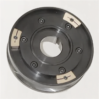
Fig. 7.17 Grinding wheel balancing with 3 counterweights
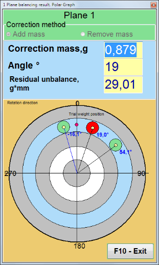
Fig. 7.18 Grinding wheel balancing. Polar graph.

Fig. 7.15. Result tab. Fixed position of correction weight mounting.
Z1 ו-Z2 – מיקומי משקולות התיקון המותקנות, מחושבות ממיקום Z1 בהתאם לכיוון הסיבוב. Z1 הוא המיקום שבו הותקנה משקולת הניסיון.
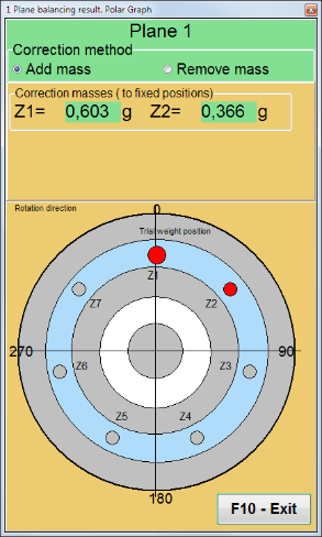
Fig. 7.16 Fixed positions. Polar diagram.
- "Mass mount radius, mm"" - "מישור 1" - רדיוס משקולת הניסיון במישור 1. נדרש לחשב את גודל חוסר האיזון ההתחלתי והשיורי כדי לקבוע עמידה בסבולת לחוסר איזון שיורי לאחר האיזון.
- "Leave trial weight in Plane1.""בדרך כלל משקולת הניסיון מוסרת במהלך תהליך האיזון. אך במקרים מסוימים אי אפשר להסירה, ואז צריך לסמן סימן אישור כדי להתחשב במסת משקולת הניסיון בחישובים.".
- "קלט נתונים ידני"" - משמש להזנה ידנית של ערך הרטט והפאזה לשדות המתאימים בצד שמאל של החלון ולחישוב המסה וזווית ההתקנה של משקל התיקון בעת מעבר ל""Results""כרטיסייה
- כפתור ""Restore session data"". במהלך האיזון, הנתונים הנמדדים נשמרים בקובץ session1.ini. אם תהליך המדידה הופרע עקב קפיאת המחשב או מסיבות אחרות, על ידי לחיצה על כפתור זה ניתן לשחזר את נתוני המדידה ולהמשיך באיזון מרגע ההפסקה.
- Mandrel eccentricity elimination (Index balancing) Balancing with additional start to eliminate the influence of the eccentricity of the mandrel (balancing arbor). Mount the rotor alternately at 0° and 180° relative to the. Measure the unbalances in both positions.
- Balancing tolerance Entering or calculating residual imbalance tolerances in g x mm (G-classes)
- Use Polar Graph Use polar graph to display balancing results
1-plane Balancing. New rotor
כפי שצוין לעיל, ""New Rotor"איזון דורש שתי ריצות בדיקה ולפחות ריצת חיתוך אחת של מכונת האיזון.
Run#0 (Initial run)
לאחר התקנת החיישנים על הרוטור המאוזן והזנת פרמטרי ההגדרות, יש להפעיל את סיבוב הרוטור, וכאשר הוא מגיע למהירות עבודה, יש ללחוץ על כפתור ""Run#0"כפתור " כדי להתחיל מדידות. ה-""Charts"הכרטיסייה " תיפתח בחלונית הימנית, שם יוצגו צורת הגל והספקטרום של הרטט. בחלק התחתון של הכרטיסייה נשמר קובץ היסטוריה, שבו נשמרות תוצאות כל ההתחלות עם ייחוס זמן. בדיסק, קובץ זה נשמר בתיקיית הארכיון בשם memo.txt
תשומת הלב!
Before starting the measurement, it is necessary to turn on the rotation of the rotor of the balancing machine (Run#0) and make sure that the rotor speed is stable.
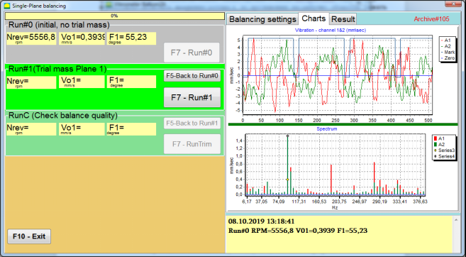
Fig. 7.19. Balancing in one plane. Initial run (Run#0). Charts Tab
After measurement process finished, in the Run#0 בחלק השמאלי מופיעות תוצאות המדידה - מהירות הרוטור (סל"ד), RMS (Vo1) ופאזה (F1) של רטט 1x.
ה""F5-Back to Run#0"כפתור " (או מקש הפונקציה F5) משמש לחזרה לקטע Run#0, ובמידת הצורך, למדידה חוזרת של פרמטרי הרטט.
Run#1 (Trial mass Plane 1)
לפני תחילת מדידת פרמטרי הרטט בסעיף ""Run#1 (Trial mass Plane 1), יש להתקין משקולת ניסיון בהתאם ל""Trial weight mass"" שדה.
The goal of installing a trial weight is to evaluate how the vibration of the rotor changes when a known weight is installed at a known place (angle). Trial weight must changes the vibration amplitude by either 30% lower or higher of initial amplitude or change phase by 30 degrees or more of initial phase.
אם יש צורך להשתמש ב-""Saved coeff.""איזון לעבודה נוספת, מיקום (זווית) התקנת משקולת הניסיון חייב להיות זהה למיקום (זווית) הסימן המחזיר אור.
הפעל שוב את סיבוב הרוטור של מכונת האיזון וודא שתדירות הסיבוב שלו יציבה. לאחר מכן לחץ על ""F7-Run#1"" (או לחץ על מקש F7 במקלדת המחשב).
לאחר המדידה בחלונות המתאימים של ה-""Run#1 (Trial mass Plane 1)"בסעיף ", מופיעות תוצאות מדידת מהירות הרוטור (סל"ד), כמו גם ערך רכיב ה-RMS (Vо1) והפאזה (F1) של רטט 1x.
במקביל, ה""Result"הכרטיסייה " נפתחת בצד ימין של החלון.
This tab displays the results of calculating the mass and angle of corrective weight, which must be installed on the rotor to compensate imbalance.
יתר על כן, במקרה של שימוש במערכת הקואורדינטות הקוטביות, התצוגה מציגה את ערך המסה (M1) ואת זווית ההתקנה (f1) של משקולת התיקון.
במקרה של ""Fixed positions"יוצגו מספרי המיקומים (Zi, Zj) ומסה מפוצלת לפי משקל הניסיון.
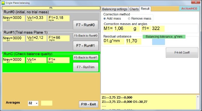
Fig. 7.20. Balancing in one plane. Run#1 and balancing result.
If גרף קוטבי is checked polar diagram will be shown.
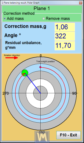
Fig. 7.21. The result of balancing. Polar graph.
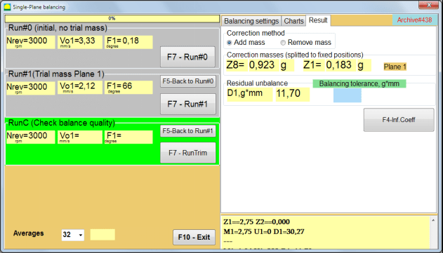
Fig. 7.22. The result of balancing. Weight splitted (fixed positions)
גם אם ""גרף קוטבי""סומן, יוצג גרף פולארי.
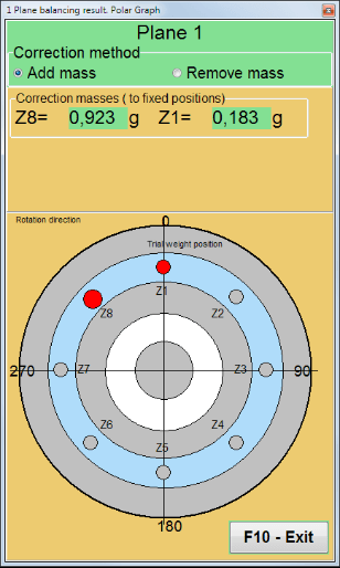
Fig. 7.23. Weight splitted on fixed positions. Polar graph
⚠️ שימו לב!
- לאחר השלמת תהליך המדידה בריצה השנייה (""Run#1 (Trial mass Plane 1)"") של מכונת האיזון, יש צורך לעצור את הסיבוב ולהסיר את משקולת הניסיון המותקנת. לאחר מכן, יש להתקין (או להסיר) את משקולת התיקון על הרוטור בהתאם לנתוני לשונית התוצאות.
אם משקולת הניסיון לא הוסרה, עליך לעבור ל""Balancing settings""טאב והפעל את תיבת הסימון ב""Leave trial weight in Plane1"". לאחר מכן חזור ל-""Result"" כרטיסייה. המשקל וזווית ההתקנה של משקל התיקון מחושבים מחדש באופן אוטומטי.
- מיקום הזווית של המשקולת המתוקנת מתבצע ממקום התקנת משקולת הניסיון. כיוון הייחוס של הזווית תואם את כיוון הסיבוב של הרוטור.
- במקרה של ""Fixed position"" - ה-1st position (Z1), coincides with the place of installation of the trial weight. The counting direction of the position number is in the direction of rotation of the rotor.
- כברירת מחדל, המשקל המתקן יתווסף לרוטור. זה מצוין על ידי התווית שנקבעה ב-""Add"" שדה. אם מסירים את המשקולת (לדוגמה, על ידי קידוח), עליכם לסמן בתוך ""Delete"", ולאחר מכן המיקום הזוויתי של משקולת התיקון ישתנה אוטומטית ב-180 מעלות.
לאחר התקנת משקולת התיקון על רוטור האיזון בחלון ההפעלה, יש צורך לבצע RunC (טרימץ) ולהעריך את יעילות האיזון שבוצע.
RunC (Check balance quality)
⚠️ שימו לב! Before starting the measurement on the RunC, it is necessary to turn on the rotation of the rotor of the machine and make sure that it has entered the operating mode (stable rotation frequency).
כדי לבצע מדידת רעידות ב""RunC (Check balance quality)"", לחץ על הקטע ""F7 – RunTrim"" (או לחיצה על מקש F7 במקלדת).
עם השלמת תהליך המדידה בהצלחה, ב""RunC (Check balance quality)"בקטע " בפאנל השמאלי, מופיעות תוצאות מדידת מהירות הרוטור (RPM), כמו גם ערך רכיב ה-RMS (Vo1) והפאזה (F1) של רטט 1x.
ב""Result"בכרטיסייה ", מוצגות תוצאות חישוב המסה וזווית ההתקנה של המשקל המתקן הנוסף.
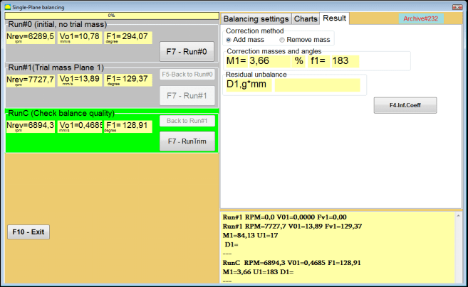
Fig. 7.24. Balancing in one plane. Performing a RunTrim. Result Tab
This weight can be added to the correction weight that is already mounted on the rotor to compensate for the residual imbalance. In addition, the residual rotor unbalance achieved after balancing is displayed in the lower part of this window.
In the case when the amount of residual vibration and / or residual unbalance of the balanced rotor meets the tolerance requirements established in the technical documentation, the balancing process can be completed.
Otherwise, the balancing process may continue. This allows the method of successive approximations to correct possible errors that may occur during the installation (removal) of the corrective weight on a balanced rotor.
בעת המשך תהליך האיזון על רוטור האיזון, יש צורך להתקין (להסיר) מסה מתקנת נוספת, אשר הפרמטרים שלה מצוינים בסעיף ""Correction masses and angles".
Influence coefficients (1-plane)
ה""F4-Inf.Coeff"כפתור " בתוך ה""Result"הכרטיסייה " משמשת לצפייה ואחסון בזיכרון המחשב של מקדמי איזון הרוטור (מקדמי השפעה) המחושבים מתוצאות ריצות הכיול.
כאשר לוחצים עליו, ה-""Influence coefficients (single plane)"יופיע חלון " על צג המחשב, שבו מוצגים מקדמי איזון המחושבים מתוצאות ריצות הכיול (בדיקה). אם במהלך האיזון הבא של מכונה זו, היא אמורה להשתמש ב-""Saved coeff."במצב ", מקדמים אלה חייבים להיות מאוחסנים בזיכרון המחשב.
לשם כך, לחצו על ה""F9 - שמירה"" כפתור ועבור לעמוד השני של ""ארכיון מקדמי השפעה. מישור יחיד."

Fig. 7.25. Balancing coefficients in the 1st plane
לאחר מכן עליך להזין את שם המכונה הזו ב-""Rotor""עמודה ולחץ על""F2-Save"" כדי לשמור את הנתונים שצוינו במחשב.
לאחר מכן ניתן לחזור לחלון הקודם על ידי לחיצה על הלחצן ""F10-Exit"כפתור " (או מקש הפונקציה F10 במקלדת המחשב).
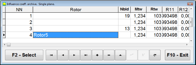
איור 7.26. "ארכיון מקדמי השפעה. מישור יחיד.""
Balancing report
לאחר איזון כל הנתונים שנשמרו ויצירת דוח איזון, ניתן לצפות ולערוך את הדוח בעורך המובנה. בחלון ""איזון ארכיון במישור אחד"" (איור 7.9) לחץ על כפתור ""F9 -Report"" כדי לגשת לעורך דוח האיזון.
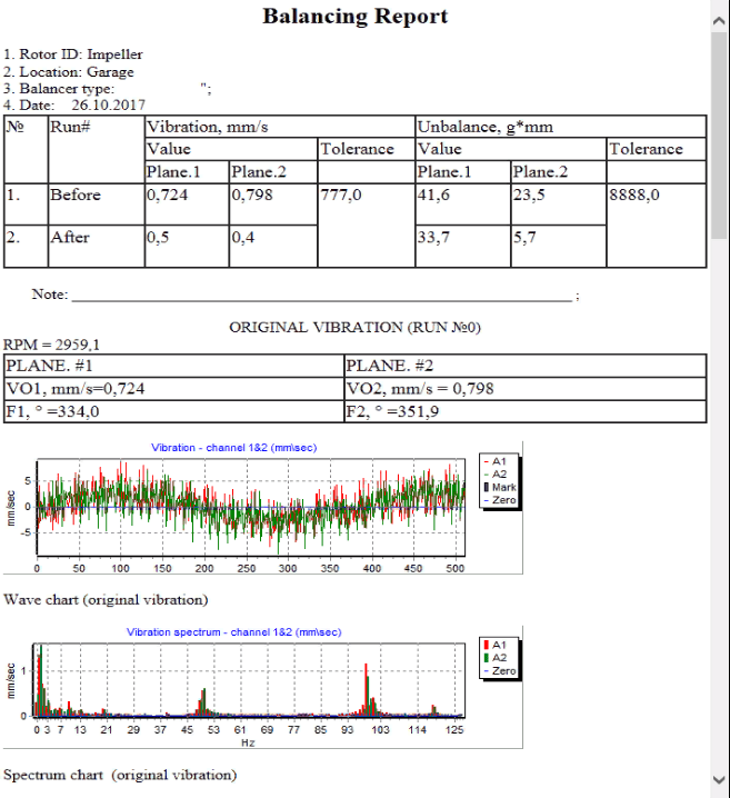
איור 7.27. דוח איזון.
הליך איזון מקדמים שנשמר עם מקדמי השפעה שנשמרו במישור אחד
הגדרת מערכת המדידה (הזנת נתונים ראשוניים)
Saved coeff. balancing can be performed on a machine for which balancing coefficients have already been determined and entered into the computer memory.
⚠️ שימו לב! When balancing with saved coefficients, the vibration sensor and the phase angle sensor must be installed in the same way as during the initial balancing.
Input of the initial data for Saved coeff. balancing (כמו במקרה של ראשוני(""New rotor"") איזון) מתחיל ב-""Single plane balancing. Balancing settings.".
במקרה זה, ב""Influence coefficients"", בחר את ה""Saved coeff""פריט. במקרה זה, העמוד השני של ה""Influence coeff. archive. Single plane.", אשר מאחסן ארכיון של מקדמי האיזון שנשמרו.
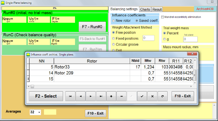
Fig. 7.28. Balancing with saved influence coefficients in 1 plane
במעבר בין טבלת הארכיון באמצעות לחצני הבקרה "►" או "◄", ניתן לבחור את הרשומה הרצויה עם מקדמי האיזון של המכונה שמעניינת אותנו. לאחר מכן, כדי להשתמש בנתונים אלה במדידות הנוכחיות, לחצו על הלחצן ""F2 – Select"כפתור ".
לאחר מכן, תוכן כל שאר החלונות של ""Single plane balancing. Balancing settings."" מתמלאים אוטומטית.
After completing the input of the initial data, you can begin to measure.
מדידות במהלך איזון עם מקדמי השפעה שנשמרו
Balancing with saved influence coefficients requires only one initial run and at least one test run of the balancing machine.
⚠️ שימו לב! Before starting the measurement, it is necessary to turn on the rotation of the rotor and make sure that rotating frequency is stable.
כדי לבצע את מדידת פרמטרי הרטט ב""Run#0 (Initial, no trial mass)""מקטע, לחץ על""F7 – Run#0"" (או ללחוץ על מקש F7 במקלדת המחשב).
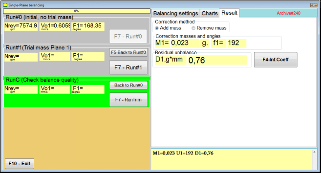
Fig. 7.29. Balancing with saved influence coefficients in one plane. Results after one run.
בשדות המתאימים של ""Run#0"בסעיף ", מופיעות תוצאות מדידת מהירות הרוטור (סל"ד), ערך רכיב ה-RMS (Vо1) והפאזה (F1) של רטט 1x.
במקביל, ה""Result"הכרטיסייה " מציגה את תוצאות חישוב המסה והזווית של משקולת התיקון, אשר יש להתקין על הרוטור כדי לפצות על חוסר איזון.
יתר על כן, במקרה של שימוש במערכת קואורדינטות פולאריות, התצוגה מציגה את ערכי המסה ואת זוויות ההתקנה של משקולות התיקון.
In the case of splitting of the corrective weight on the fixed positions, the numbers of the positions of the balancing rotor and the mass of weight that need to be installed on them are displayed.
Further, the balancing process is carried out in accordance with the recommendations set out in section 7.4.2. for primary balancing.
Mandrel eccentricity elimination (Index balancing)
If during balancing the rotor is installed in a cylindrical mandrel, then the eccentricity of the mandrel may introduce an additional error. To eliminate this error, the rotor should be deployed in the mandrel 180 degrees and carry out an additional start. This is called index balancing.
To carry out index balancing, a special option is provided in the Balanset-1A program. When checked Mandrel eccentricity elimination an additional RunEcc section appears in the balancing window.

Fig. 7.30. The working window for Index balancing.
After running Run # 1 (Trial mass Plane 1), a window will appear
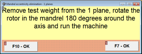
Fig. 7.31 Index balancing attention window.
לאחר התקנת הרוטור בסיבוב של 180°, יש להשלים את Run Ecc. התוכנית תחשב אוטומטית את חוסר האיזון האמיתי של הרוטור מבלי להשפיע על האקסצנטריות של המנדרל.
7.5 איזון דו-מישורי
Before starting work in the Two plane balancing mode, it is necessary to install vibration sensors on the machine body at the selected measurement points and connect them to the inputs X1 and X2 of the measuring unit, respectively.
An optical phase angle sensor must be connected to input X3 of the measuring unit. In addition, to use this sensor, a reflective tape must be glued onto the accessible rotor surface of the balancing machine.
Detailed requirements for choosing the installation location of sensors and their mounting at the facility during balancing are set out in Appendix 1.
העבודה על התוכנית ב""Two plane balancing"מצב " מתחיל מהחלון הראשי של התוכניות.
לחץ על ה""F3-Two plane"" (או לחץ על מקש F3 במקלדת המחשב).
לאחר מכן, לחצו על כפתור "F7 – איזון", ולאחר מכן יופיע חלון עבודה על צג המחשב (ראה איור 7.13), בחירת הארכיון לשמירת נתונים בעת איזון בשני מישורים.
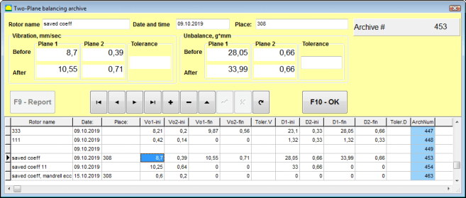
Fig. 7.32 Two plane balancing archive window.
בחלון זה עליך להזין את נתוני הרוטור המאוזן. לאחר לחיצה על ""F10-OK"", יופיע חלון איזון.
Balancing settings (2-plane)
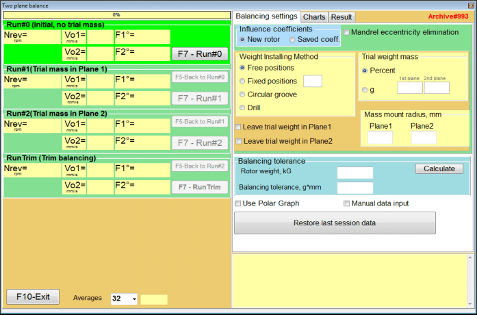
Fig. 7.33. Balancing in two planes window.
בצד ימין של החלון נמצא ה""Balancing settings"" כרטיסייה להזנת הגדרות לפני איזון.
- Influence coefficients - איזון רוטור חדש או איזון באמצעות מקדמי השפעה מאוחסנים (מקדמי איזון)
- Mandrel eccentricity elimination - איזון עם התחלת סיבוב נוספת כדי לבטל את השפעת האקסצנטריות של המנדרל
- Weight Attachment Method - התקנת משקולות תיקון במקום שרירותי על היקף הרוטור או במיקום קבוע. חישובים לקידוח בעת הסרת המסה.
- "Free position""- ניתן להתקין משקולות בזווית שרירותית על היקף הרוטור.
- "Fixed position""- ניתן להתקין משקולת במיקומים זוויתיים קבועים על הרוטור, לדוגמה, על להבים או חורים (לדוגמה 12 חורים - 30 מעלות), וכו'. יש להזין את מספר המיקומים הקבועים בשדה המתאים. לאחר האיזון, התוכנית תפצל אוטומטית את המשקולת לשני חלקים ותציין את מספר המיקומים שעליהם יש לקבוע את המסות המתקבלות.
- Trial weight mass - משקל ניסיון
- Leave trial weight in Plane1 / Plane2 - הסירו או השאירו את משקולת הניסיון בעת האיזון.
- Mass mount radius, mm - רדיוס משקולות ניסיון ומשקולות תיקון להרכבה
- Balancing tolerance - הזנה או חישוב של סבילות חוסר איזון שיורי ב-g-mm
- Use Polar Graph - השתמש בגרף פולארי כדי להציג תוצאות איזון
- קלט נתונים ידני - הזנת נתונים ידנית לחישוב משקלי איזון
- Restore last session data - שחזור נתוני המדידה של הסשן האחרון במקרה של כשל בהמשך האיזון.
2 planes balancing. New rotor
הגדרת מערכת המדידה (הזנת נתונים ראשוניים)
Input of the initial data for the New rotor balancing ב""איזון דו-מישורי. הגדרות".
במקרה זה, ב""Influence coefficients"", בחר את ה""New rotor""פריט.
בהמשך, בסעיף ""Trial weight mass"", עליך לבחור את יחידת המידה של מסת משקולת הניסיון - ""Gram"" או ""Percent".
בעת בחירת יחידת המידה ""Percent"", כל החישובים הנוספים של מסת המשקל המתוקן יבוצעו כאחוזים ביחס למסת משקולת הניסיון.
בעת בחירת ה""Gram""יחידת מידה, כל החישובים הנוספים של מסת המשקל המתוקן יבוצעו בגרמים. לאחר מכן הזינו בחלונות הממוקמים מימין לכיתוב ""Gram""מסת משקולות הניסיון שיותקנו על הרוטור.".
⚠️ שימו לב! אם יש צורך להשתמש ב-""Saved coeff.""מצב לעבודה נוספת במהלך האיזון הראשוני, יש להזין את מסת משקולות הניסיון ב grams.
לאחר מכן בחר ""Weight Attachment Method" - "Circum"" או ""Fixed position".
אם תבחרו ""Fixed position"", עליך להזין את מספר המיקומים.
Calculation of tolerance for residual imbalance (Balancing tolerance)
ניתן לחשב את הסבילות לחוסר איזון שיורי (סבילות איזון) בהתאם לנוהל המתואר בתקן ISO 1940 רטט. דרישות איכות איזון לרוטורים במצב קבוע (קשיח). חלק 1. מפרט ואימות של סבילות איזון.

איור 7.34. חלון חישוב סובלנות איזון
Initial run (Run#0)
כאשר מאזנים בשני מישורים ב""New rotor"במצב ", איזון דורש שלוש ריצות כיול ולפחות ריצת בדיקה אחת של מכונת האיזון.
מדידת הרטט בהפעלה הראשונה של המכונה מבוצעת ב-""Two plane balance""חלון עבודה ב""Run#0""סעיף.
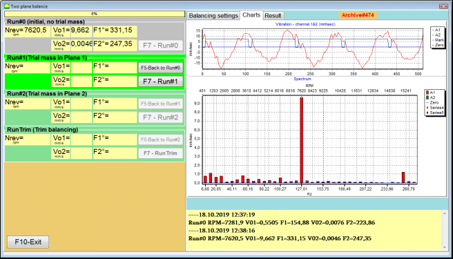
איור 7.35. תוצאות המדידה באיזון בשני מישורים לאחר הריצה הראשונית.
⚠️ שימו לב! לפני תחילת המדידה, יש להפעיל את סיבוב הרוטור של מכונת האיזון (הפעלה ראשונה) ולוודא שהיא נכנסה למצב פעולה במהירות יציבה.
To measure vibration parameters in the Run#0 סעיף, לחץ על ""F7 – Run#0"כפתור " (או לחיצה על מקש F7 במקלדת המחשב)
תוצאות מדידת מהירות הרוטור (RPM), ערך ה-RMS (VО1, VО2) והפאזות (F1, F2) של רטט 1x מופיעות בחלונות המתאימים של Run#0 section.
Run#1.Trial mass in Plane1
לפני שמתחילים למדוד פרמטרי רטט ב-""Run#1.Trial mass in Plane1"בסעיף ", עליך לעצור את סיבוב הרוטור של מכונת האיזון ולהתקין עליו משקולת ניסיון, המסה שנבחרה ב""Trial weight mass""סעיף.
⚠️ שימו לב!
- שאלת בחירת המסה של משקולות ניסיון ומקומות ההתקנה שלהן על הרוטור של מכונת איזון נדונה בפירוט בנספח 1.
- אם יש צורך להשתמש ב- Saved coeff. Mode in future work, the place for installing the trial weight must necessarily coincide with the place for installing the mark used to read the phase angle.
After this, it is necessary to turn on the rotation of the rotor of the balancing machine again and make sure that it has entered the operating mode.
כדי למדוד פרמטרי רטט ב-""Run # 1.Trial mass in Plane1"", לחץ על הקטע ""F7 – Run#1"" (או לחץ על מקש F7 במקלדת המחשב).
לאחר השלמת תהליך המדידה בהצלחה, תוחזר ללשונית תוצאות המדידה.
במקרה זה, בחלונות המתאימים של ""Run#1. Trial mass in Plane1"בסעיף ", תוצאות מדידת מהירות הרוטור (סל"ד), כמו גם ערך רכיבי ה-RMS (Vо1, Vо2) והפאזות (F1, F2) של רטט 1x.
""הפעל # 2. מסה ניסיונית במישור 2""
לפני שמתחילים למדוד פרמטרי רטט בסעיף ""Run # 2.Trial mass in Plane2"", עליך לבצע את השלבים הבאים:
- לעצור את סיבוב הרוטור של מכונת האיזון;
- הסר את משקולת הניסיון המותקנת במישור 1;
- התקן משקולת ניסיון במישור 2, המסה שנבחרה בסעיף ""Trial weight mass".
After this, turn on the rotation of the rotor of the balancing machine and make sure that it has entered the operating speed.
כדי להתחיל את מדידת הרטט ב""Run # 2.Trial mass in Plane2"", לחץ על הקטע ""F7 – Run # 2"" (או לחץ על מקש F7 במקלדת המחשב). לאחר מכן, הלחצן ""Result""הכרטיסייה נפתחת.
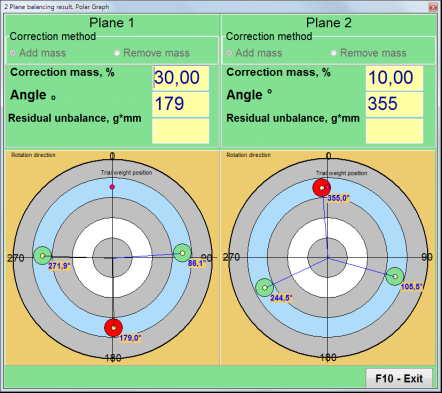
In the case of using the Weight Attachment Method" - "Free positions, התצוגה מציגה את ערכי המסה (M1, M2) וזוויות ההתקנה (f1, f2) של משקולות התיקון.
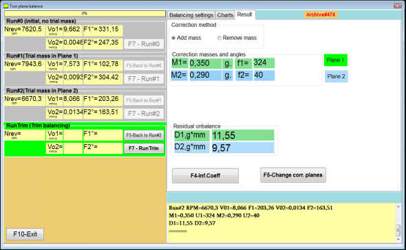
Fig. 7.36. Results of calculation of corrective weights – free position
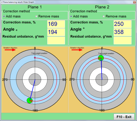
איור 7.37. תוצאות חישוב משקולות תיקון - מיקום חופשי. דיאגרמת פולאר
In the case of using the Weight Attachment Method" – "Fixed positions

איור 7.38. תוצאות חישוב משקולות תיקון - מיקום קבוע.
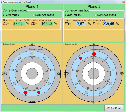
איור 7.39. תוצאות חישוב משקולות תיקון - מיקום קבוע. דיאגרמת פולאר.
במקרה של שימוש בשיטת חיבור המשקולות" – ""Circular groove"
איור 7.40. תוצאות חישוב משקולות תיקון - חריץ מעגלי.
⚠️ שימו לב!
- לאחר השלמת תהליך המדידה על RUN#2 of the balancing machine, stop the rotation of the rotor and remove the trial weight previously installed. Then you can to install (or remove) corrective weights.
- המיקום הזוויתי של משקולות התיקון במערכת הקואורדינטות הקוטביות נספר ממקום התקנת משקולת הניסיון בכיוון סיבוב הרוטור.
- במקרה של ""Fixed position"" - ה-1st position (Z1), coincides with the place of installation of the trial weight. The counting direction of the position number is in the direction of rotation of the rotor.
- כברירת מחדל, המשקל המתקן יתווסף לרוטור. זה מצוין על ידי התווית שנקבעה ב-""Add"" שדה. אם מסירים את המשקולת (לדוגמה, על ידי קידוח), עליכם לסמן בתוך ""Delete"", ולאחר מכן המיקום הזוויתי של משקולת התיקון ישתנה אוטומטית ב-180 מעלות.
RunC (Trim run)
After installing the correction weight on the balancing rotor it is necessary to carry out a RunC (trim) and evaluate the effectiveness of the performed balancing.
⚠️ שימו לב! לפני תחילת המדידה בהרצה, יש להפעיל את סיבוב הרוטור של המכונה ולוודא שהיא נכנסה למהירות פעולה.
כדי למדוד פרמטרי רטט בקטע RunTrim (בדיקת איכות איזון), לחץ על הסמל ""F7 – RunTrim"" (או לחץ על מקש F7 במקלדת המחשב).
The results of measuring the rotor rotation frequency (RPM), as well as the value of the RMS component (Vо1) and phase (F1) of 1x vibration will be shown.
ה""Result"הכרטיסייה " מופיעה בצד ימין של חלון העבודה עם טבלת תוצאות המדידה, המציגה את תוצאות חישוב הפרמטרים של משקלים מתקנים נוספים.
These weights can be added to corrective weights that are already installed on the rotor to compensate for residual imbalance.
In addition, the residual rotor unbalance achieved after balancing is displayed in the lower part of this window.
במקרה בו ערכי הרטט השיורי ו/או חוסר האיזון השיורי של הרוטור המאוזן עומדים בדרישות הסבילות שנקבעו בתיעוד הטכני, ניתן להשלים את תהליך האיזון.
Otherwise, the balancing process may continue. This allows the method of successive approximations to correct possible errors that may occur during the installation (removal) of the corrective weight on a balanced rotor.
בעת המשך תהליך האיזון על רוטור האיזון, יש צורך להתקין (להסיר) מסה מתקנת נוספת, אשר הפרמטרים שלה מצוינים בחלון "תוצאה".
ב""Result""בחלון ישנם שני כפתורי בקרה שניתן להשתמש בהם -""F4-Inf.Coeff", "F5 – Change correction planes".
Influence coefficients (2 planes)
ה""F4-Inf.Coeff"כפתור " (או מקש הפונקציה F4 במקלדת המחשב) משמש לצפייה ושמירה של מקדמי איזון הרוטור בזיכרון המחשב, המחושבים מתוצאות שתי התחלות כיול.
כאשר לוחצים עליו, ה-""Influence coefficients (two planes)"מופיע חלון עבודה על צג המחשב, שבו מוצגים מקדמי איזון המחושבים על סמך תוצאות שלוש התחלות הכיול הראשונות.

Fig. 7.41. Working window with balancing coefficients in 2 planes.
בעתיד, בעת איזון של מכונה מסוג זה, יש צורך להשתמש ב-""Saved coeff.""מצב ומקדמי איזון המאוחסנים בזיכרון המחשב.
כדי לשמור מקדמים, לחצו על הלחצן ""F9 – Save"כפתור " ועבור אל ""Influence coefficients archive (2planes)""חלונות (ראה איור 7.42)
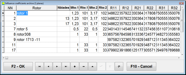
Fig. 7.42. The second page of the working window with balancing coefficients in 2 planes.
Change correction planes
ה""F5 – Change correction planes"הכפתור " משמש כאשר יש צורך לשנות את מיקום מישורי התיקון, כאשר יש צורך לחשב מחדש את המסות ואת זוויות ההתקנה או את המשקולות לתיקון.
This mode is primarily useful when balancing rotors of complex shape (for example, crankshafts).
כאשר לוחצים על כפתור זה, חלון העבודה ""Recalculation of correction weights mass and angle to other correction planes"" מוצג על צג המחשב.
In this working window, you should select one of the 4 possible options by clicking corresponding picture.
מישורי התיקון המקוריים (Н1 ו-Н2) מסומנים בירוק, והחדשים (K1 ו-K2), שעבורם הוא מסופר, באדום.
לאחר מכן, ב""Calculation data"בסעיף ", הזן את הנתונים המבוקשים, כולל:
- המרחק בין מישורי התיקון המתאימים (a, b, c);
- ערכים חדשים של רדיוסי התקנת משקולות תיקון על הרוטור (R1', R2').
לאחר הזנת הנתונים, עליך ללחוץ על הכפתור ""F9-calculate"
תוצאות החישוב (מסות M1, M2 וזוויות התקנה של משקולות תיקון f1, f2) מוצגות בחלק המתאים של חלון עבודה זה.
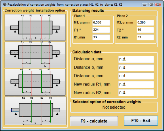
איור 7.43 שינוי מישורי תיקון. חישוב מחדש של מסת התיקון והזווית למישורי תיקון אחרים.
איזון מקדם שמור בשני מישורים
Saved coeff. balancing can be performed on a machine for which balancing coefficients have already been determined and saved in the computer memory.
⚠️ שימו לב! When re-balancing, the vibration sensors and the phase angle sensor must be installed in the same way as during the initial balancing.
הזנת נתונים ראשוניים לאיזון מחדש מתחילה ב-""איזון דו-מישורי. הגדרות איזון".
במקרה זה, ב""Influence coefficients"", בחר את ה""Saved coeff.""פריט. במקרה זה, החלון""Influence coefficients archive (2planes)"" יופיע, בו מאוחסן ארכיון מקדמי האיזון שנקבעו קודם לכן.
במעבר בין טבלת הארכיון באמצעות לחצני הבקרה "►" או "◄", ניתן לבחור את הרשומה הרצויה עם מקדמי האיזון של המכונה שמעניינת אותנו. לאחר מכן, כדי להשתמש בנתונים אלה במדידות הנוכחיות, לחצו על הלחצן ""F2 – OK"" ולחזור לחלון העבודה הקודם.
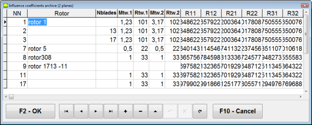
Fig. 7.44. The second page of the working window with balancing coefficients in 2 planes.
לאחר מכן, תוכן כל שאר החלונות של ""איזון ב-2 נקודות. נתוני מקור"" מתמלא אוטומטית.
Saved coeff. Balancing
"Saved coeff."איזון דורש רק התחלת כוונון אחת ולפחות התחלת בדיקה אחת של מכונת האיזון.
Vibration measurement at the tuning start (Run # 0) של המכונה מתבצעת ב-""Balancing in 2 planes""חלון עבודה עם טבלת תוצאות איזון ב Run # 0 section.
⚠️ שימו לב! Before starting the measurement, it is necessary to turn on the rotation of the rotor of the balancing machine and make sure that it has entered the operating mode with a stable speed.
To measure vibration parameters in the Run # 0 סעיף, לחץ על ""F7 – Run#0"" (או לחץ על מקש F7 במקלדת המחשב).
The results of measuring the rotor speed (RPM), as well as the value of the components of the RMS (VО1, VО2) and phases (F1, F2) of the 1x vibration appear in the corresponding fields of the Run # 0 section.
במקביל, ה""Result"נפתחת הכרטיסייה ", המציגה את תוצאות חישוב הפרמטרים של משקולות תיקון שיש להתקין על הרוטור כדי לפצות על חוסר האיזון שלו.
יתר על כן, במקרה של שימוש במערכת הקואורדינטות הקוטביות, התצוגה מציגה את ערכי המסה וזוויות ההתקנה של משקולות תיקון.
In the case of decomposition of corrective weights on the blades, the numbers of the blades of the balancing rotor and the mass of weight that need to be installed on them are displayed.
Further, the balancing process is carried out in accordance with the recommendations set out in section 7.6.1.2. for primary balancing.
⚠️ שימו לב!
- After completion of the measurement process after the second start of the balanced machine stop the rotation of its rotor and remove the previously set trial weight. Only then you can begin to install (or remove) correction weight on the rotor.
- Counting the angular position of the place of adding (or removing) of the correction weight from the rotor is carried out on the installation site of trial weight in the polar coordinate system. Counting direction coincides with the direction of the angle of rotor rotation.
- במקרה של איזון על הלהבים - להב הרוטור המאוזן, המסומן כמיקום 1, תואם את מקום התקנת משקולת הניסיון. כיוון מספר ההתייחסות של הלהב המוצג על צג המחשב מתבצע בכיוון סיבוב הרוטור.
- בגרסה זו של התוכנית, כברירת מחדל, יתווסף משקל תיקון לרוטור. התג שנקבע בשדה "הוספה" מעיד על כך. במקרה של תיקון חוסר איזון על ידי הסרת משקולת (לדוגמה על ידי קידוח), יש צורך להגדיר תג בשדה "הסרה", ואז המיקום הזוויתי של משקולת התיקון ישתנה אוטומטית ב-180 מעלות.
ביטול אקסצנטריות של המנדרל (איזון אינדקס) - שני מישורים
If during balancing the rotor is installed in a cylindrical mandrel, then the eccentricity of the mandrel may introduce an additional error. To eliminate this error, the rotor should be deployed in the mandrel 180 degrees and carry out an additional start. This is called index balancing.
To carry out index balancing, a special option is provided in the Balanset-1A program. When checked Mandrel eccentricity elimination an additional RunEcc section appears in the balancing window.
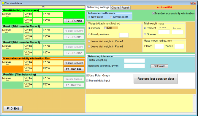
Fig. 7.45. The working window for Index balancing.
After running Run # 2 (Trial mass Plane 2), a window will appear
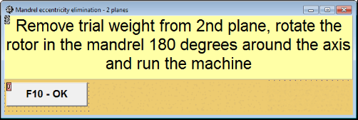
Fig. 7.46. Attention windows
לאחר התקנת הרוטור בסיבוב של 180°, יש להשלים את Run Ecc. התוכנית תחשב אוטומטית את חוסר האיזון האמיתי של הרוטור מבלי להשפיע על האקסצנטריות של המנדרל.
7.6 מצב תרשימים
העבודה במצב "תרשימים" מתחילה מחלון ההתחלתי (ראה איור 7.1) על ידי לחיצה על ""F8 – תרשימים". לאחר מכן נפתח חלון "מדידת רטט בשני ערוצים. תרשימים" (ראה איור 7.19).

איור 7.47. חלון הפעלה "מדידת רעידות בשני ערוצים. תרשימים".
While working in this mode it is possible to plot four versions of vibration chart.
The first version allows to get a timeline function of the overall vibration (of vibration velocity) on the first and second measuring channels.
The second version allows you to get graphs of vibration (of vibration velocity), which occurs on rotation frequency and its higher harmonical components.
These graphs are obtained as a result of the synchronous filtering of the overall vibration time function.
The third version provides vibration charts with the results of the harmonical analysis.
The fourth version allows to get a vibration chart with the results of the spectrum analysis.
תרשימים של רטט כולל
כדי לשרטט תרשים רעידות כולל בחלון ההפעלה ""Measurement of vibration on two channels. Charts"יש צורך לבחור את מצב ההפעלה"overall vibration"" על ידי לחיצה על הכפתור המתאים. לאחר מכן הגדירו את מדידת הרטט בתיבה "משך זמן, בשניות", על ידי לחיצה על הכפתור "▼" ובחרו מהרשימה הנפתחת את משך הזמן הרצוי של תהליך המדידה, שיכול להיות שווה ל-1, 5, 10, 15 או 20 שניות;
לאחר המוכנות, לחץ (לחץ) על ה""F9לחץ על כפתור "מדידה" ואז תהליך מדידת הרטט מתחיל בו זמנית בשני ערוצים.
After completion of the measurement process in the operating window appear charts of time function of the overall vibration of the first (red) and the second (green) channels (see. Fig. 7.47).
On these charts time is plotted on X-axis and the amplitude of the vibration velocity (mm/sec) is plotted on Y-axis.
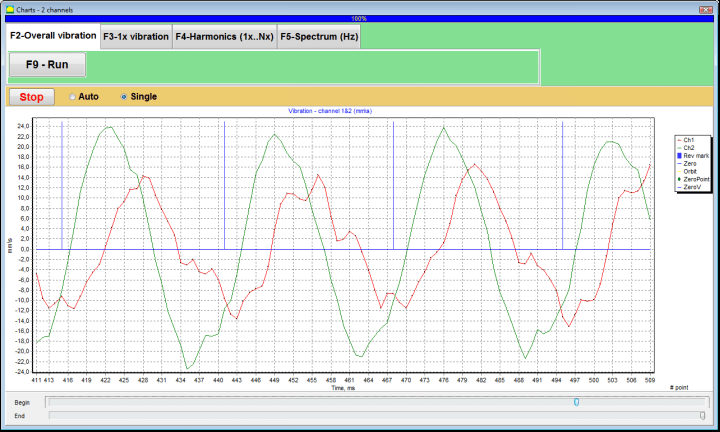
איור 7.48. חלון הפעלה לפלט פונקציית הזמן של תרשימי הרטט הכוללים
There are also marks (blue-colored) in these graphs connecting charts of overall vibration with the rotation frequency of the rotor. In addition, each mark indicates beginning (end) of the next revolution of the rotor.
In need of the scale change of the chart on X-axis the slider, pointed by an arrow on fig. 7.20, can be used.
תרשימים של רטט 1x
כדי לשרטט תרשים רעידות 1x בחלון ההפעלה ""Measurement of vibration on two channels. Charts"יש צורך לבחור את מצב ההפעלה"1x vibration""על ידי לחיצה על הכפתור המתאים.
לאחר מכן מופיע חלון הפעלה "רטט 1x".
לחץ (לחץ) על ה""F9לחץ על כפתור "מדידה" ואז תהליך מדידת הרטט מתחיל בו זמנית בשני ערוצים.
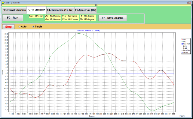
איור 7.49. חלון הפעלה לפלט של תרשימי הרטט 1x.
After completion of the measurement process and mathematical calculation of results (synchronous filtering of the time function of the overall vibration) on display in the main window on a period equal to one revolution of the rotor appear charts of the 1x vibration on two channels.
In this case, a chart for the first channel is depicted in red and for the second channel in green. On these charts angle of the rotor revolution is plotted (from mark to mark) on X-axis and the amplitude of the vibration velocity (mm/sec) is plotted on Y-axis.
בנוסף, בחלק העליון של חלון העבודה (מימין לכפתור ""F9 – מדידה"") ערכים מספריים של מדידות רטט של שני הערוצים, בדומה לאלה שאנו מקבלים ב""Vibration meter"מצב ", מוצגים.
In particular: RMS value of the overall vibration (V1s, V2s), the magnitude of RMS (V1o, V2o) and phase (Fi, Fj) of the 1x vibration and rotor speed (Nrev).
תרשימי רטט עם תוצאות ניתוח הרמוני
כדי לשרטט תרשים עם תוצאות הניתוח ההרמוני בחלון ההפעלה ""Measurement of vibration on two channels. Charts"יש צורך לבחור את מצב ההפעלה"Harmonical analysis""על ידי לחיצה על הכפתור המתאים.
לאחר מכן מופיע חלון הפעלה לפלט בו זמנית של תרשימים של פונקציה זמנית ושל ספקטרום של היבטים הרמוניים של רטט, שתקופתם שווה או כפולה מתדר סיבוב הרוטור.
תשומת הלב!
When operating in this mode it is necessary to use the phase angle sensor which synchronizes the measurement process with the rotor frequency of the machines to which the sensor is set.
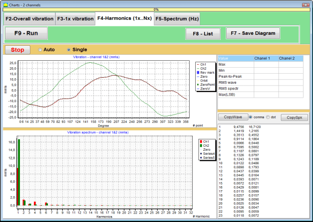
איור 7.50. הרמוניות חלון פעולה של רטט 1x.
לאחר המוכנות, לחץ (לחץ) על ה""F9לחץ על כפתור "מדידה" ואז תהליך מדידת הרטט מתחיל בו זמנית בשני ערוצים.
לאחר השלמת תהליך המדידה, מופיעים בחלון ההפעלה גרפים של פונקציית זמן (גרף עליון) והרמוניות של רטט פי 1 (גרף תחתון).
The number of harmonic components is plotted on X-axis and RMS of the vibration velocity (mm/sec) is plotted on Y-axis.
תרשימים של תחום זמן וספקטרום הרטט
כדי לשרטט תרשים ספקטרום השתמש ב""F5-ספקטרום""כרטיסייה:
לאחר מכן מופיע חלון הפעלה לפלט בו זמנית של תרשימי גל וספקטרום של רטט.

איור 7.51. חלון הפעלה לפלט ספקטרום הרטט.
לאחר המוכנות, לחץ (לחץ) על ה""F9לחץ על כפתור "מדידה" ואז תהליך מדידת הרטט מתחיל בו זמנית בשני ערוצים.
לאחר השלמת תהליך המדידה, בחלון ההפעלה מופיעים גרפים של פונקציית זמן (גרף עליון) וספקטרום רטט (גרף תחתון).
The vibration frequency is plotted on X-axis and RMS of the vibration velocity (mm/sec) is plotted on Y-axis.
In this case, a chart for the first channel is depicted in red and for the second channel in green.
8. הוראות כלליות לתפעול ותחזוקה של המכשיר
8.1 קריטריוני איכות איזון (תקן ISO 2372)
ניתן להעריך את איכות האיזון באמצעות רמות רטט שנקבעו בתקן ISO 2372. הטבלה שלהלן מציגה רמות רטט מקובלות עבור סוגי מכונות שונים:
| מחלקת מכונה | טוֹב (מ"מ/שנייה RMS) |
קָבִיל (מ"מ/שנייה RMS) |
עדיין מקובל (מ"מ/שנייה RMS) |
לא מקובל (מ"מ/שנייה RMS) |
|---|---|---|---|---|
| כיתה 1 מכונות קטנות על יסודות קשיחים (מנועים עד 15 קילוואט) |
< 0.7 | 0.7 - 1.8 | 1.8 - 4.5 | > 4.5 |
| כיתה 2 מכונות בינוניות ללא יסודות (מנועים 15-75 קילוואט), מנגנוני הנעה עד 300 קילוואט |
< 1.1 | 1.1 - 2.8 | 2.8 - 7.1 | > 7.1 |
| כיתה 3 מכונות גדולות על יסודות קשיחים (ציוד מעל 300 קילוואט) |
< 1.8 | 1.8 - 4.5 | 4.5 - 11 | > 11 |
| כיתה 4 מכונות גדולות על יסודות קלים (ציוד מעל 300 קילוואט) |
< 2.8 | 2.8 - 7.1 | 7.1 - 18 | > 18 |
הערה: ערכים אלה מספקים הנחיות להערכת איכות האיזון. יש לעיין תמיד במפרטים הספציפיים של יצרן הציוד ובתקנים הרלוונטיים ליישום שלך.
8.2 דרישות תחזוקה
🔧 תחזוקה שוטפת
- ✓כיול קבוע של חיישנים בהתאם למפרטי היצרן
- ✓שמרו על חיישנים נקיים וחופשיים מלכלוך מגנטי
- ✓יש לאחסן את הציוד במארז מגן כאשר אינו בשימוש
- ✓הגן על חיישן הלייזר מפני אבק ולחות
- ✓בדקו באופן קבוע את חיבורי הכבלים לאיתור בלאי או נזק
- ✓עדכון תוכנה לפי המלצת היצרן
- ✓שמור עותקי גיבוי של נתוני איזון חשובים
📋 תקני תחזוקה של האיחוד האירופי
תחזוקת הציוד חייבת לעמוד בדרישות:
- תקן EN ISO 9001: דרישות מערכות ניהול איכות
- EN 13306: מונחים והגדרות תחזוקה
- EN 15341: מדדי ביצועי מפתח של תחזוקה
- בדיקות בטיחות תקופתיות בהתאם להנחיית מכונות של האיחוד האירופי
נספח 1. איזון רוטור
הרוטור הוא גוף המסתובב סביב ציר מסוים ומוחזק על ידי משטחי המיסב שלו בתומכים. משטחי המיסב של הרוטור מעבירים משקלים לתומכים באמצעות מיסבים מתגלגלים או הזזה. בשימוש במונח "משטח מיסב" אנו מתייחסים פשוט למשטחי ציר* או למשטחים המחליפים את ציר הציר.
*יומן (Zapfen בגרמנית פירושו "יומן", "פין") - הוא חלק מציר או פיר, הנישא על ידי מחזיק (תיבת מיסב).
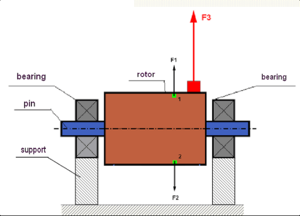
fig.1 Rotor and centrifugal forces.
In a perfectly balanced rotor, its mass is distributed symmetrically regarding the axis of the rotation. This means that any element of the rotor can correspond to another element located symmetrically in a relation to the axis of the rotation. During rotation, each rotor element acts upon by a centrifugal force directed in the radial direction (perpendicular to the axis of the rotor rotation). In a balanced rotor, the centrifugal force influencing any element of the rotor is balanced by the centrifugal force that influences the symmetrical element. For example, elements 1 and 2 (shown in fig.1 and colored in green) are influenced by centrifugal forces F1 and F2: equal in value and absolutely opposite in directions. This is true for all symmetrical elements of the rotor and thus the total centrifugal force influencing the rotor is equal to 0 the rotor is balanced. But if the symmetry of the rotor is broken (in Figure 1, the asymmetric element is marked in red), then the unbalanced centrifugal force F3 begins to act on the rotor.
בעת סיבוב, כוח זה משנה את כיוון הסיבוב יחד עם סיבוב הרוטור. העומס הדינמי הנובע מכוח זה מועבר למסבים, מה שמוביל לבלאי מואץ שלהם. בנוסף, תחת השפעת כוח משתנה זה, מתרחשת עיוות מחזורי של התומכים ושל היסודות שעליהם הרוטור קבוע, מה שיוצר רטט. כדי לבטל את חוסר האיזון של הרוטור ואת הרטט הנלווה, יש צורך להגדיר מסות איזון, שישקמו את הסימטריה של הרוטור.
Rotor balancing is an operation to eliminate imbalance by adding balancing masses.
The task of balancing is to find the value and places (angle) of the installation of one or more balancing masses.
סוגי הרוטורים וחוסר האיזון
Considering the strength of the rotor material and the magnitude of the centrifugal forces influencing it, the rotors can be divided into two types: rigid and flexible.
רוטורים קשיחים בתנאי הפעלה תחת השפעת כוח צנטריפוגלי עלולים להתעוות מעט, אך לכן ניתן להזניח את השפעת עיוות זה בחישובים.
Deformation of flexible rotors on the other hand should never be neglected. The deformation of flexible rotors complicates the solution for the balancing problem and requires the use of some other mathematical models in comparison with the task of balancing rigid rotors. It is important to mention that the same rotor at low speeds of rotation can behave like rigid one and at high speeds it will behave like flexible one. Further on we will consider the balancing of rigid rotors only.
בהתאם לפיזור המסות הלא מאוזנות לאורך הרוטור, ניתן להבחין בין שני סוגים של חוסר איזון - סטטי ודינמי. אותו הדבר חל על איזון הרוטור הסטטי והדינמי.
חוסר איזון סטטי של הרוטור מתרחש ללא סיבוב הרוטור. במילים אחרות, הוא במצב שקט כאשר הרוטור נמצא תחת השפעת כוח הכבידה ובנוסף הוא מפנה את "הנקודה הכבדה" כלפי מטה. דוגמה לרוטור עם חוסר איזון סטטי מוצגת באיור 2.

Fig.2
The dynamic imbalance occurs only when the rotor spins.
An example of a rotor with the dynamic imbalance is presented in Fig.3.
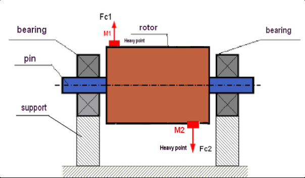
Fig.3. Dynamic imbalance of rotor – couple of the centrifugal forces
במקרה זה, מסות שוות ולא מאוזנות M1 ו-M2 ממוקמות על משטחים שונים - במקומות שונים לאורך הרוטור. במצב סטטי, כלומר כאשר הרוטור אינו מסתובב, הרוטור עשוי להיות מושפע רק מכוח הכבידה ולכן המסות יאזנו זו את זו. בדינמיקה כאשר הרוטור מסתובב, המסות M1 ו-M2 מתחילות להיות מושפעות מכוחות צנטריפוגליים FΎ1 ו-FΎ2. כוחות אלה שווים בערכם ומנוגדים בכיוונם. עם זאת, מכיוון שהם ממוקמים במקומות שונים לאורך הציר ואינם נמצאים באותו קו, הכוחות אינם מפצים זה את זה. הכוחות FΎ1 ו-FΎ2 יוצרים מומנט הפועל על הרוטור. זו הסיבה שלחוסר איזון זה יש שם נוסף "רגעי". בהתאם לכך, כוחות צנטריפוגליים לא מפוצים פועלים על תומכי המיסבים, אשר יכולים לעלות משמעותית על הכוחות עליהם הסתמכנו וגם לקצר את חיי השירות של המיסבים.
מכיוון שסוג זה של חוסר איזון מתרחש רק בדינמיקה במהלך סיבוב הרוטור, הוא נקרא דינמי. לא ניתן לבטל אותו באיזון סטטי (או מה שנקרא "על הסכינים") או בכל דרך דומה אחרת. כדי לבטל את חוסר האיזון הדינמי, יש צורך להגדיר שני משקולות פיצוי שייצרו מומנט שווה בערכו והפוך בכיוונו למומנט הנובע מהמסות M1 ו-M2. מסות פיצוי אינן חייבות להיות מותקנות בהכרח מול המסות M1 ו-M2 ולהיות שוות להן בערכן. הדבר החשוב ביותר הוא שהן ייצרו מומנט שמפצה באופן מלא בדיוק ברגע חוסר האיזון.
באופן כללי, המסות M1 ו-M2 עשויות לא להיות שוות זו לזו, כך שיהיה שילוב של חוסר איזון סטטי ודינמי. תיאורטית הוכח שכדי שרוטור קשיח יבטל את חוסר האיזון שלו, יש צורך ומספיק להתקין שתי משקולות המרווחות לאורך הרוטור. משקולות אלו יפצו הן את המומנט הנובע מחוסר האיזון הדינמי והן את הכוח הצנטריפוגלי הנובע מאסימטריה של המסה ביחס לציר הרוטור (חוסר איזון סטטי). כרגיל, חוסר האיזון הדינמי אופייני לרוטורים ארוכים, כמו צירים, וסטטי - לרוטורים צרים. עם זאת, אם הרוטור הצר מותקן בצורה מוטה ביחס לציר, או גרוע מכך, מעוות (מה שנקרא "תנועות גלגל"), במקרה זה יהיה קשה לבטל את חוסר האיזון הדינמי (ראה איור 4), בשל העובדה שקשה להגדיר משקולות תיקון, היוצרות את מומנט הפיצוי הנכון.
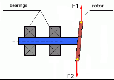
Fig.4 Dynamic balancing of the wobbling wheel
מכיוון שכתף הרוטור הצרה יוצרת מומנט קצר, ייתכן שיהיה צורך לתקן משקולות של מסה גדולה. אך יחד עם זאת, קיים מה שנקרא "חוסר איזון מושרה" נוסף הקשור לעיוות הרוטור הצר תחת השפעת כוחות צנטריפוגליים מהמסות המתקנות.
See the example:
""הוראות מתודולוגיות לאיזון רוטורים קשיחים"" ISO 1940-1:2003 Mechanical vibration – Balance quality requirements for rotors in a constant (rigid) state – Part 1: Specification and verification of balance tolerances
This is visible for narrow fan wheels, which, in addition to the power imbalance, also influences an aerodynamic imbalance. And it is important to bear in mind that the aerodynamic imbalance, in fact the aerodynamic force, is directly proportional to the angular velocity of the rotor, and to compensate it, the centrifugal force of the correcting mass is used, which is proportional to the square of the angular velocity. Therefore, the balancing effect may only occur at a specific balancing frequency. At other speeds there would be an additional gap. The same can be said about electromagnetic forces in an electromagnetic motor, which are also proportional to the angular velocity. In other words it is impossible to eliminate all causes of vibration of the mechanism by any means of balancing.
יסודות הרטט
ויברציה היא תגובה של תכנון המנגנון להשפעת כוח עירור מחזורי. כוח זה יכול להיות בעל אופי שונה.
- הכוח הצנטריפוגלי הנובע מחוסר איזון של הרוטור הוא כוח לא מפוצה המשפיע על "הנקודה הכבדה". כוח זה, וגם הרטט הנגרם ממנו, מתבטלים על ידי איזון הרוטור.
- כוחות אינטראקטיביים, בעלי אופי "גיאומטרי" הנובעים משגיאות בייצור ובהתקנה של חלקים מתחברים. כוחות אלה יכולים להתרחש, למשל, עקב חוסר עיגול של יונת הציר, שגיאות בפרופילי השיניים בגלגלי השיניים, גליות מסילות המיסב, חוסר יישור של צירי החיבור וכו'. במקרה של חוסר עיגול של הצווארים, ציר הציר יזוז בהתאם לזווית הסיבוב של הציר. למרות שרטט זה מתבטא במהירות הרוטור, כמעט בלתי אפשרי לבטל אותו באמצעות איזון.
- Aerodynamic forces arising from the rotation of the impeller fans and other blade mechanisms. Hydrodynamic forces arising from the rotation of hydraulic pump impellers, turbines, etc.
- כוחות אלקטרומגנטיים הנובעים מהפעלת מכונות חשמליות כתוצאה, למשל, מאסימטריה של פיתולי הרוטור, נוכחות של סיבובים קצרים וכו'.
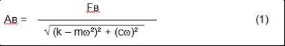
The magnitude of vibration (for example, its amplitude AB) depends not only on the magnitude of the excitation force Fт acting on the mechanism with the circular frequency ω, but also on the stiffness k of the structure of the mechanism, its mass m, and damping coefficient C.
Various types of sensors can be used to measure vibration and balance mechanisms, including:
- absolute vibration sensors designed to measure vibration acceleration (accelerometers) and vibration velocity sensors;
- חיישני רטט יחסיים, זרמי מערבולת או קיבוליים, שנועדו למדוד רטט.
In some cases (when the structure of the mechanism allows it) sensors of force can also be used to examine its vibration weight.
Particularly, they are widely used to measure the vibration weight of the supports of hardbearing balancing machines.
Therefore vibration is the reaction of the mechanism to the influence of external forces. The amount of vibration depends not only on the magnitude of the force acting on the mechanism, but also on the rigidity of the mechanism. Two forces with the same magnitude can lead to different vibrations. In mechanisms with a rigid support structure, even with the small vibration, the bearing units can be significantly influenced by dynamic weights. Therefore, when balancing mechanisms with stiff legs apply the force sensors, and vibration (vibro accelerometers). Vibration sensors are only used on mechanisms with relatively pliable supports, right when the action of unbalanced centrifugal forces leads to a noticeable deformation of the supports and vibration. Force sensors are used in rigid supports even when significant forces arising from imbalance do not lead to significant vibration.
התהודה של המבנה
We have previously mentioned that rotors are divided into rigid and flexible. The rigidity or flexibility of the rotor should not be confused with the stiffness or mobility of the supports (foundation) on which the rotor is located. The rotor is considered rigid when its deformation (bending) under the action of centrifugal forces can be neglected. The deformation of the flexible rotor is relatively large: it cannot be neglected.
במאמר זה אנו חוקרים רק את איזון הרוטורים הנוקשים. הרוטור הנוקשה (שאינו ניתן לעיוות) בתורו יכול להיות ממוקם על תומכים נוקשים או ניידים (ניתנים לגמישות). ברור כי קשיחות/ניידות זו של התומכים היא יחסית בהתאם למהירות סיבוב הרוטור ולגודל הכוחות הצנטריפוגליים הנובעים מכך. הגבול המקובל הוא תדירות התנודות החופשיות של תומכי/יסודות הרוטור. עבור מערכות מכניות, צורתן ותדירותן של התנודות החופשיות נקבעות על ידי המסה והאלסטיות של רכיבי המערכת המכנית. כלומר, תדירותן של התנודות הטבעיות היא מאפיין פנימי של המערכת המכנית ואינה תלויה בכוחות חיצוניים. בהיותם מוסטים ממצב שיווי המשקל, תומכים נוטים לחזור למצב שיווי המשקל שלהם עקב האלסטיות. אך עקב האינרציה של הרוטור המסיבי, תהליך זה הוא בגדר תנודות מרוסנות. תנודות אלו הן תנודות משלהן של מערכת הרוטור-תמיכה. תדירותן תלויה ביחס בין מסת הרוטור לגמישות התומכים.
When the rotor begins to rotate and the frequency of its rotation approaches the frequency of its own oscillations, the vibration amplitude increases sharply, which can even lead to the destruction of the structure.
There is a phenomenon of mechanical resonance. In the resonance region, a change in the speed of rotation by 100 rpm can lead to an increase in a vibration tenfold. In this case (in the resonance region) the vibration phase changes by 180°.
אם תכנון המנגנון גרוע, ומהירות הפעולה של הרוטור קרובה לתדירות הטבעית של התנודות, פעולת המנגנון הופכת לבלתי אפשרית עקב רעידות גבוהות באופן בלתי מתקבל על הדעת. שיטות איזון סטנדרטיות גם הן בלתי אפשריות, שכן הפרמטרים משתנים באופן דרמטי אפילו עם שינוי קל במהירות הסיבוב. נעשה שימוש בשיטות מיוחדות בתחום איזון התהודה, אך הן אינן מתוארות היטב במאמר זה. ניתן לקבוע את תדירות התנודות הטבעיות של המנגנון על ידי סיבוב (כאשר הרוטור כבוי) או על ידי פגיעה, ולאחר מכן ניתוח ספקטרלי של תגובת המערכת לזעזוע. "Balanset-1" מספק את היכולת לקבוע את התדרים הטבעיים של מבנים מכניים באמצעות שיטות אלו.
For mechanisms whose operating speed is higher than the resonance frequency, that is, operating in the resonant mode, supports are considered as mobile ones and vibration sensors are used to measure, mainly vibration accelerometers that measure the acceleration of structural elements. For mechanisms operating in hard bearing mode, supports are considered as rigid. In this case, force sensors are used.
מודלים ליניאריים ולא ליניאריים של מערכת מכנית
Mathematical models (linear) are used for calculations when balancing rigid rotors. The linearity of the model means that one model is directly proportionally (linearly) dependent on the other. For example, if the uncompensated mass on the rotor is doubled, then the vibration value will be doubled correspondingly. For rigid rotors you can use a linear model because such rotors are not deformed. It is no longer possible to use a linear model for flexible rotors. For a flexible rotor, with an increase of the mass of a heavy point during rotation, an additional deformation will occur, and in addition to the mass, the radius of the heavy point will also increase. Therefore, for a flexible rotor, the vibration will more than double, and the usual calculation methods will not work. Also, a violation of the linearity of the model can lead to a change in the elasticity of the supports at their large deformations, for example, when small deformations of the supports work some structural elements, and when large in the work include other structural elements. Therefore it is impossible to balance the mechanisms that are not fixed at the base, and, for example, are simply established on a floor. With significant vibrations, the unbalance force can detach the mechanism from the floor, thereby significantly changing the stiffness characteristics of the system. The engine legs must be securely fastened, bolted fasteners tightened, the thickness of the washers must provide sufficient rigidity, etc. With broken bearings, a significant displacement of the shaft and its impacts is possible, which will also lead to a violation of linearity and the impossibility of carrying out high-quality balancing.
Methods and devices for balancing
As mentioned above, balancing is the process of combining the main Central axis of inertia with the axis of rotation of the rotor.
The specified process can be executed in two ways.
The first method involves the processing of the rotor axles, which is performed in such a way that the axis passing through the centers of the section of the axles with the main Central axis of inertia of the rotor. This technique is rarely used in practice and will not be discussed in detail in this article.
The second (most common) method involves moving, installing or removing corrective masses on the rotor, which are placed in such a way that the axis of inertia of the rotor is as close as possible to the axis of its rotation.
Moving, adding or removing corrective masses during balancing can be done using a variety of technological operations, including: drilling, milling, surfacing, welding, screwing or unscrewing screws, burning with a laser beam or electron beam, electrolysis, electromagnetic welding, etc.
The balancing process can be performed in two ways:
- מכלול רוטורים מאוזנים (במיסבים משלו);
- איזון רוטורים על מכונות איזון.
To balance the rotors in their own bearings we usually use specialized balancing devices (kits), which allows us to measure the vibration of the balanced rotor at the speed of its rotation in a vector form, i.e. to measure both the amplitude and phase of vibration.
Currently, these devices are manufactured on the basis of microprocessor technology and (in addition to the measurement and analysis of vibration) provide automated calculation of the parameters of corrective weights that must be installed on the rotor to compensate its imbalance.
These devices include:
- יחידת מדידה וחישוב, המיוצרת על בסיס מחשב או בקר תעשייתי;
- שני (או יותר) חיישני רטט;
- חיישן זווית פאזה;
- ציוד להתקנת חיישנים במתקן;
- תוכנה ייעודית שנועדה לבצע מחזור מדידה מלא של פרמטרי חוסר איזון של הרוטור במישור תיקון אחד, שניים או יותר.
לאיזון רוטורים במכונות איזון, בנוסף למכשיר איזון מיוחד (מערכת מדידה של המכונה), נדרש "מנגנון פריקה" שנועד להתקין את הרוטור על התומכים ולהבטיח את סיבובו במהירות קבועה.
Currently, the most common balancing machines exist in two types:
- תהודה יתר על המידה (עם תמיכה גמישה);
- מיסב קשיח (עם תומכים נוקשים).
Over-resonant machines have a relatively pliable supports, made, for example, on the basis of the flat springs.
The natural oscillation frequency of these supports is usually 2-3 times lower than the speed of the balanced rotor, which is mounted on them.
Vibration sensors (accelerometers, vibration velocity sensors, etc.) are usually used to measure the vibration of the supports of a resonant machine.
In the hardbearing balancing machines are used relatively-rigid supports, natural oscillation frequencies of which should be 2-3 times higher than the speed of the balanced rotor.
Force sensors are usually used to measure the vibration weight on the supports of the machine.
The advantage of the hard bearing balancing machines is that they can be balanced at relatively low rotor speeds (up to 400-500 rpm), which greatly simplifies the design of the machine and its foundation, as well as increases the productivity and safety of balancing.
Balancing technique
⚠️ איזון מבטל רק את הרטט שנגרם עקב אסימטריה של פיזור המסה של הרוטור ביחס לציר הסיבוב שלו. לא ניתן לבטל סוגים אחרים של רטט באמצעות איזון!
Balancing is the subject to technically serviceable mechanisms, the design of which ensures the absence of resonances at the operating speed, securely fixed on the foundation, installed in serviceable bearings.
🚫 המנגנון התקול דורש תיקון, ורק אז – איזון. אחרת, איזון איכותי בלתי אפשרי.
Balancing cannot be a substitute for repair!
The main task of balancing is to find the mass and the place (angle) of installation of compensating weights, which are balanced by centrifugal forces.
As mentioned above, for rigid rotors it is generally necessary and sufficient to install two compensating weights. This will eliminate both the static and dynamic rotor imbalance. A general scheme of the vibration measurement during balancing looks like the following:
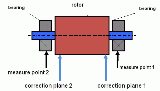
fig.5 Dynamic balancing – correction planes and measure points
Vibration sensors are installed on the bearing supports at points 1 and 2. The speed mark is fixed right on the rotor, a reflective tape is glued usually. The speed mark is used by the laser tachometer to determine the speed of the rotor and the phase of the vibration signal.
איור 6. התקנת חיישנים במהלך איזון בשני מישורים, באמצעות Balanset-1
1,2-vibration sensors, 3-phase, 4- USB measuring unit, 5-laptop
In most cases, dynamic balancing is carried out by the method of three starts. This method is based on the fact that test weights of an already-known mass are installed on the rotor in series in 1 and 2 planes; so the masses and the place of installation of balancing weights are calculated based on the results of changing the vibration parameters.
מקום התקנת המשקולת נקרא מישור התיקון. בדרך כלל, מישורי התיקון נבחרים באזור תומכי המיסב שעליהם מורכב הרוטור.
התנודה הראשונית נמדדת בהפעלה הראשונה. לאחר מכן, משקולת ניסיון בעלת מסה ידועה מותקנת על הרוטור קרוב יותר לאחד התומכים. לאחר מכן מתבצעת ההפעלה השנייה, ואנו מודדים את פרמטרי התנודה, שאמורים להשתנות עקב התקנת משקולת הניסיון. לאחר מכן, משקולת הניסיון במישור הראשון מוסרת ומותקנת במישור השני. מתבצעת ההפעלה השלישית ונמדדים פרמטרי התנודה. כאשר משקולת הניסיון מוסרת, התוכנה מחשבת באופן אוטומטי את המסה ואת המיקום (הזוויות) של התקנת משקולות האיזון.
The point in setting up test weights is to determine how the system responds to the imbalance change. When we know the masses and the location of the sample weights, the program can calculate the so-called influence coefficients, showing how the introduction of a known imbalance affects the vibration parameters. The coefficients of influence are the characteristics of the mechanical system itself and depend on the stiffness of the supports and the mass (inertia) of the rotor-support system.
For the same type of mechanisms of the same design, the coefficients of influence will be similar. You can save them in your computer memory and use them afterwards for balancing the same type of mechanisms without carrying out test runs, which greatly improves the performance of the balancing. We should also note that the mass of test weights should be chosen as such so that the vibration parameters vary markedly when installing test weights. Otherwise, the error in calculating the coefficients of the affect increases and the quality of balancing deteriorates.
מדריך למכשיר Balanset-1 מספק נוסחה שבאמצעותה ניתן לקבוע בקירוב את מסת משקולת הניסיון, בהתאם למסה ולמהירות הסיבוב של הרוטור המאוזן. כפי שניתן להבין מאיור 1, הכוח הצנטריפוגלי פועל בכיוון הרדיאלי, כלומר בניצב לציר הרוטור. לכן, יש להתקין חיישני רטט כך שציר הרגישות שלהם מכוון גם לכיוון הרדיאלי. בדרך כלל, קשיחות היסוד בכיוון האופקי נמוכה יותר, ולכן הרטט בכיוון האופקי גבוה יותר. לכן, כדי להגביר את רגישות החיישנים, יש להתקין כך שציר הרגישות שלהם יוכל להיות מכוון גם אופקית. למרות שאין הבדל מהותי. בנוסף לרטט בכיוון הרדיאלי, יש צורך לשלוט ברטט בכיוון הצירי, לאורך ציר הסיבוב של הרוטור. רטט זה נגרם בדרך כלל לא מחוסר איזון, אלא מסיבות אחרות, בעיקר עקב חוסר יישור וחוסר יישור של צירים המחוברים דרך המצמד. רטט זה אינו מבוטל על ידי איזון, במקרה זה נדרש יישור. בפועל, בדרך כלל במנגנונים כאלה יש חוסר איזון של הרוטור וחוסר יישור של הצירים, מה שמסבך מאוד את משימת ביטול הרטט. במקרים כאלה, יש תחילה ליישר ולאחר מכן לאזן את המנגנון. (אם כי בחוסר איזון מומנט חזק, רטט מתרחש גם בכיוון הצירי עקב "פיתול" מבנה היסוד).
דיוק מדידה וניתוח שגיאות
הבנת דיוק המדידה היא קריטית לפעולות איזון מקצועיות. ה-Balanset-1A מספק את דיוק המדידה הבא:
| פָּרָמֶטֶר | נוסחת דיוק | דוגמה (לערכים אופייניים) |
|---|---|---|
| מהירות רטט RMS | ±(0.1 + 0.1×Vנמדד) מ"מ/שנייה | עבור 5 מ"מ/שנייה: ±0.6 מ"מ/שנייה עבור 10 מ"מ/שנייה: ±1.1 מ"מ/שנייה |
| תדירות סיבוב | ±(1 + 0.005×Nנמדד) סל"ד | עבור 1000 סל"ד: ±6 סל"ד עבור 3000 סל"ד: ±16 סל"ד |
| מדידת פאזה | ±1° | דיוק קבוע בכל המהירויות |
⚠️ קריטי לאיזון מדויק
- !משקל הניסיון חייב לגרום לשינוי משרעת >20-30% ו/או שינוי פאזה >20-30°
- !אם השינויים קטנים יותר, שגיאות המדידה גדלות משמעותית
- !אמפליטודת הרטט ויציבות הפאזה לא צריכות להשתנות ביותר מ-10-15% בין מדידות.
- !אם השונות עולה על 15%, יש לבדוק אם קיימים תנאי תהודה או בעיות מכניות.
קריטריונים להערכת איכות מנגנוני האיזון
Quality of rotor (mechanisms) balancing can be estimated in two ways. The first method involves comparing the value of the residual imbalance determined during the balancing with the tolerance for the residual imbalance. The specified tolerances for various classes of rotors installed in the standard ISO 1940-1-2007. «רטט. דרישות לאיכות האיזון של רוטורים קשיחים. חלק 1. קביעת חוסר איזון מותר".
עם זאת, יישום סבולות אלו אינו יכול להבטיח באופן מלא את אמינות התפעול של המנגנון הקשורה להשגת רמת רטט מינימלית. זאת בשל העובדה שרטט המנגנון נקבע לא רק על ידי כמות הכוח הקשורה לחוסר האיזון השיורי של הרוטור שלו, אלא תלוי גם במספר פרמטרים אחרים, כולל: קשיחות K של האלמנטים המבניים של המנגנון, המסה M שלו, מקדם הריסון והמהירות. לכן, כדי להעריך את התכונות הדינמיות של המנגנון (כולל איכות האיזון שלו) במקרים מסוימים, מומלץ להעריך את רמת הרטט השיורי של המנגנון, המווסתת על ידי מספר תקנים.
The most common standard regulating permissible vibration levels of mechanisms is ISO 10816-3:2009 תצוגה מקדימה של רעידות מכניות - הערכת רעידות מכונה על ידי מדידות על חלקים שאינם מסתובבים - חלק 3: מכונות תעשייתיות בעלות הספק נומינלי מעל 15 קילוואט ומהירויות נומינליות בין 120 סל"ד ל-15,000 סל"ד כאשר נמדדות באתר.»
With its help, you can set the tolerance on all types of machines, taking into account the power of their electric drive.
In addition to this universal standard, there are a number of specialized standards developed for specific types of mechanisms. For example,
- ISO 14694:2003 "מאווררים תעשייתיים - מפרטים לאיכות איזון ורמות רעידות""
- ISO 7919-1-2002 "רעידות של מכונות ללא תנועה הדדית. מדידות על צירים מסתובבים וקריטריונים להערכה. הנחיות כלליות.""
🛡️ שיקולי בטיחות חשובים לצורך תאימות לתקנות האיחוד האירופי
- !הערכת סיכונים נדרשת: בצע הערכת סיכונים לפי EN ISO 12100 לפני פעולות איזון
- !כוח אדם מוסמך: רק אנשי צוות מיומנים ומוסמכים צריכים לבצע פעולות איזון
- !ציוד מגן אישי: יש להשתמש תמיד בציוד מגן אישי מתאים לפי תקני EN 166 (הגנה על העיניים) ו- EN 352 (הגנה על השמיעה).
- !נהלי חירום: קבעו נהלי כיבוי חירום ברורים וודאו שכל המפעילים מכירים אותם
- !תיעוד: שמור תיעוד מפורט של כל פעולות האיזון לצורך מעקב ותאימות
מידע על תאימות ובטיחות של האיחוד האירופי
הצהרת תאימות
מאזן נייד מדגם Balanset-1A עומד בהנחיות ובתקנים הבאים של האיחוד האירופי:
| הנחיה/תקן של האיחוד האירופי | פרטי תאימות | דרישות בטיחות |
|---|---|---|
| הנחיית מכונות 2006/42/EC | דרישות בטיחות למכונות ורכיבי בטיחות | הערכת סיכונים, הוראות בטיחות, סימון CE |
| הנחיית EMC 2014/30/EU | דרישות תאימות אלקטרומגנטית | חסינות להפרעות אלקטרומגנטיות |
| הנחיית RoHS 2011/65/EU | הגבלת חומרים מסוכנים | רכיבים ללא עופרת, ללא כספית וללא קדמיום |
| הנחיית WEEE 2012/19/EU | פסולת ציוד חשמלי ואלקטרוני | נהלי סילוק ומיחזור נאותים |
| תקן EN ISO 12100:2010 | בטיחות מכונות - עקרונות כלליים לתכנון | הערכת סיכונים והפחתת סיכונים |
| תקן EN 60825-1:2014 | בטיחות מוצרי לייזר - חלק 1 | דרישות בטיחות לייזר מסוג 2 |
| תקן EN ISO 14120:2015 | שומרים - דרישות כלליות | הגנה מפני סכנות של מכונות מסתובבות |
תקני בטיחות חשמליים
- ✓EN 61010-1: דרישות בטיחות לציוד חשמלי למדידה, בקרה ושימוש במעבדה
- ✓EN 60950-1: בטיחות ציוד טכנולוגיית מידע (התקן מופעל באמצעות USB)
- ✓סדרת IEC 61000: תקני תאימות אלקטרומגנטית
- ✓מתח הפעלה: 5V DC דרך USB (מתח נמוך במיוחד)
- ✓צריכת חשמל: < 2.5W
- ✓דרגת הגנה: IP20 (לשימוש פנימי)
בטיחות ציוד מסתובב
⚠️ נהלי בטיחות חובה (EN ISO 12100)
אַזהָרָה: בעת עבודה עם מכונות מסתובבות, יש להקפיד על דרישות הבטיחות הבאות:
- !תקן EN ISO 14118: מניעת הפעלה בלתי צפויה - יש להשתמש בהליכי נעילה/תיוג לפני התקנת החיישן
- !תקן EN ISO 14120: ודא שכל הציוד המסתובב מוגן כראוי
- !תקן EN ISO 13857: שמרו על מרחקי בטיחות מינימליים מחלקים מסתובבים (500 מ"מ לגוף, 120 מ"מ לאצבעות)
- !ציוד מגן אישי: יש להרכיב משקפי מגן בהתאם לתקן EN 166, אמצעי הגנה לשמיעה בהתאם לתקן EN 352, ולהימנע מלבוש רפוי.
- !לעולם אל תתקינו חיישנים או משקולות ניסיון על מכונות מסתובבות בזמן תנועה
- !ודא שהמכונה נעצרת לחלוטין ומאובטחת לפני התקנת החיישן
- !עצירת חירום: יש להיות נגיש בטווח של 3 מטרים מעמדת המפעיל
- !רק אנשי צוות מוסמכים ומוסמכים צריכים לבצע פעולות איזון
סיווג בטיחות לייזר
🔴 מכשיר לייזר Class 2 (EN 60825-1:2014)
- אֹרֶך גַל: 650 ננומטר (אור אדום נראה)
- הספק פלט מרבי: < 1 מיליוואט
- קוטר הקורה: 3-5 מ"מ במרחק של 100 מ"מ
- הִסתַעֲפוּת: < 1.5 מראד
- סיווג בטיחות: בטוח לעיניים לחשיפה רגעית (< 0.25 שניות)
- תיוג נדרש: ""קרינת לייזר - אין להביט בקרן - מוצר לייזר מסוג 2""
- מחלקת גישה: ללא הגבלה (גישה כללית מותרת)
נהלי בטיחות לייזר:
- לעולם אל תבהה בכוונה בקרן לייזר
- אין לכוון לייזר לעבר אנשים, כלי רכב או מטוסים
- הימנעו מצפייה בקרן לייזר באמצעות מכשירים אופטיים (טלסקופים, משקפות)
- שימו לב להשתקפויות חדות ממשטחים מבריקים
- כבה את הלייזר כאשר אינו בשימוש
- דווחו מיד על כל אירוע חשיפה לעיניים
- השתמשו במשקפי בטיחות לייזר (OD 2+ ב-650nm) לחשיפה ממושכת
דיוק מדידה וכיול
| פָּרָמֶטֶר | דִיוּק | תדירות כיול |
|---|---|---|
| אמפליטודת הרטט | ±5% של קריאה | שנתי או לאחר 1000 שעות |
| מדידת פאזה | ±1° | מדי שנה |
| מהירות סיבוב | ±0.1% של קריאה | מדי שנה |
| רגישות החיישן | 13 מיליוולט/(מ"מ/שנייה) ±10% | בעת החלפת חיישנים |
תאימות סביבתית
- ✓סביבת הפעלה: 5°C עד 50°C, < 85% RH ללא עיבוי
- ✓סביבת אחסון: -20°C עד 70°C, < 95% לחות יחסית ללא עיבוי
- ✓גוֹבַה: עד 2000 מטר מעל פני הים
- ✓עמידות לרעידות: IEC 60068-2-6 (10-500 הרץ, תאוצה של 2 גרם)
- ✓עמידות בפני זעזועים: IEC 60068-2-27 (15 גרם, משך זמן של 11 אלפיות שנייה)
- ✓דירוג IP: IP20 (הגנה מפני עצמים מוצקים > 12 מ"מ)
דרישות תפעול
- ✓על המפעילים לעבור הכשרה בבטיחות מכונות בהתאם לתקני האיחוד האירופי
- ✓נדרשת הערכת סיכונים לפי EN ISO 12100 לפני השימוש
- ✓תחזוקת הציוד בהתאם למפרטי היצרן
- ✓דווחו מיד על כל תקלה בציוד או על תקלות בטיחותיות
- ✓שמור תיעוד מפורט של כל פעולות האיזון לצורך מעקב
דרישות תיעוד
לצורך עמידה בדרישות האיחוד האירופי, יש לשמור את התיעוד הבא:
- ✓תיעוד הערכת סיכונים לפי EN ISO 12100
- ✓רישומי הכשרה והסמכות של מפעילים
- ✓יומני כיול ותחזוקה של הציוד
- ✓איזון רשומות פעולות עם תאריכים, אופרטורים ותוצאות
- ✓דוחות אירועי בטיחות ופעולות מתקנות
- ✓תיעוד שינוי או תיקון ציוד
תמיכה ושירות טכניים
לתמיכה טכנית, שירותי כיול וחלקי חילוף:
- ✓יַצרָן: Vibromera
- ✓מִקוּם: Rua Alcaide de Faria 193, פורטו, פורטוגל
- ✓אֲתַר אִינטֶרנֶט: https://vibromera.eu
- ✓שפות תמיכה: כל השפות העיקריות. תקשורת מבוססת טקסט זמינה.
- ✓כיסוי שירות: משלוח לכל העולם זמין
- ✓אַחֲרָיוּת: 24 חודשים ממועד הרכישה
- ✓שירות כיול: זמין דרך מרכזי שירות מורשים
