अपने हाथों से मशीनों को संतुलित करना
पेशेवर स्तर की बैलेंसिंग मशीन बनाने के लिए व्यापक तकनीकी मार्गदर्शिका। सॉफ्ट बेयरिंग बनाम हार्ड बेयरिंग डिज़ाइन, स्पिंडल गणना, सपोर्ट सिस्टम और माप उपकरण एकीकरण के बारे में जानें।

विषयसूची


1. परिचय
(इस कृति को लिखने की आवश्यकता क्यों पड़ी?)
एलएलसी "किनेमेटिक्स" (वाइब्रोमेरा) द्वारा निर्मित संतुलन उपकरणों की खपत संरचना के विश्लेषण से पता चलता है कि लगभग 301टीपी3टी उपकरण संतुलन मशीनों और/या स्टैंडों के लिए स्थिर मापन और गणना प्रणालियों के रूप में उपयोग के लिए खरीदे जाते हैं। हमारे उपकरणों के उपभोक्ताओं (ग्राहकों) के दो समूह पहचाने जा सकते हैं।
पहले समूह में वे उद्यम शामिल हैं जो संतुलन मशीनों के बड़े पैमाने पर उत्पादन में विशेषज्ञता रखते हैं और उन्हें बाहरी ग्राहकों को बेचते हैं। ये उद्यम विभिन्न प्रकार की संतुलन मशीनों के डिजाइन, निर्माण और संचालन में गहरे ज्ञान और व्यापक अनुभव वाले उच्च योग्य विशेषज्ञों को रोजगार देते हैं। इस उपभोक्ता समूह के साथ बातचीत में उत्पन्न होने वाली चुनौतियाँ अक्सर हमारी मापन प्रणालियों और सॉफ़्टवेयर को मौजूदा या नव विकसित मशीनों के अनुरूप अनुकूलित करने से संबंधित होती हैं, जबकि उनकी संरचनात्मक निष्पादन से जुड़े मुद्दों का समाधान नहीं किया जाता।
दूसरा समूह उन उपभोक्ताओं का है जो अपनी आवश्यकताओं के लिए मशीनें (स्टैंड) विकसित और निर्माण करते हैं। इस दृष्टिकोण को मुख्यतः स्वतंत्र निर्माताओं की अपनी उत्पादन लागत कम करने की इच्छा से समझाया जा सकता है, जो कुछ मामलों में दो से तीन गुना या उससे अधिक तक घट सकती है। इस समूह के उपभोक्ताओं के पास अक्सर मशीनें बनाने का पर्याप्त अनुभव नहीं होता है और वे आमतौर पर सामान्य ज्ञान, इंटरनेट से प्राप्त जानकारी और अपने कार्य में उपलब्ध किसी भी समान उदाहरण पर निर्भर रहते हैं।
उनके साथ बातचीत करने से कई प्रश्न उठते हैं, जो संतुलन मशीनों की मापन प्रणालियों के बारे में अतिरिक्त जानकारी के अलावा, मशीनों के संरचनात्मक निष्पादन, नींव पर उनकी स्थापना के तरीकों, ड्राइव के चयन, और उचित संतुलन सटीकता प्राप्त करने आदि से संबंधित विभिन्न मुद्दों को कवर करते हैं।
स्वतंत्र रूप से बैलेंसिंग मशीन बनाने के मुद्दों में हमारे उपभोक्ताओं के एक बड़े समूह द्वारा दिखाई गई महत्वपूर्ण रुचि को ध्यान में रखते हुए, एलएलसी "किनेमेटिक्स" (वाइब्रोमेरा) के विशेषज्ञों ने सबसे अधिक पूछे जाने वाले प्रश्नों पर टिप्पणियों और सिफारिशों के साथ एक संकलन तैयार किया है।
2. संतुलन मशीनों (स्टैंड) के प्रकार और उनके डिज़ाइन की विशेषताएँ
एक बैलेंसिंग मशीन एक तकनीकी उपकरण है जिसे विभिन्न उद्देश्यों के लिए रोटरों के स्थैतिक या गतिशील असंतुलन को दूर करने के लिए डिज़ाइन किया गया है। इसमें एक ऐसा तंत्र शामिल होता है जो संतुलित रोटर को एक निर्दिष्ट घूर्णन आवृत्ति तक त्वरित करता है और एक विशेष मापन और गणना प्रणाली होती है जो रोटर के असंतुलन की भरपाई के लिए आवश्यक सुधारात्मक भारों के द्रव्यमान और स्थान का निर्धारण करती है।
मशीन के यांत्रिक भाग की संरचना में आमतौर पर एक बेडफ्रेम होता है जिस पर सपोर्ट पोस्ट (बेयरिंग) लगे होते हैं। इनका उपयोग संतुलित उत्पाद (रोटर) को माउंट करने के लिए किया जाता है और इनमें रोटर को घुमाने के लिए एक ड्राइव भी शामिल होती है। संतुलन प्रक्रिया के दौरान, जो उत्पाद के घूमते समय की जाती है, मापन प्रणाली के सेंसर (जिनका प्रकार मशीन के डिज़ाइन पर निर्भर करता है) या तो बेयरिंग में कंपन या बेयरिंग पर लगने वाले बल को रिकॉर्ड करते हैं।
इस प्रकार प्राप्त डेटा असंतुलन की भरपाई के लिए आवश्यक सुधारात्मक भारों के द्रव्यमान और स्थापना स्थानों को निर्धारित करने की अनुमति देता है।
वर्तमान में, दो प्रकार के संतुलन मशीन (स्टैंड) डिज़ाइन सबसे अधिक प्रचलित हैं:
- सॉफ्ट बेयरिंग मशीनें (लचीले सहारे के साथ);
- हार्ड बेयरिंग मशीनें (कठोर सहाराओं के साथ)
2.1. सॉफ्ट बेयरिंग मशीनें और स्टैंड
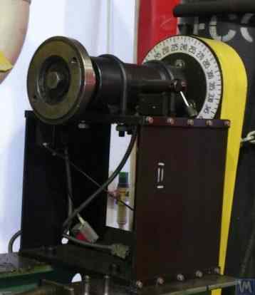
सॉफ्ट बेयरिंग संतुलन मशीनों (स्टैंड्स) की मूलभूत विशेषता यह है कि इनमें स्प्रिंग सस्पेंशन, स्प्रिंग-माउंटेड कैरिज, फ्लैट या सिलेंड्रिक स्प्रिंग सपोर्ट आदि के आधार पर बनाए गए अपेक्षाकृत लचीले सपोर्ट होते हैं। इन सपोर्टों की प्राकृतिक आवृत्ति, उन पर स्थापित संतुलित रोटर की घूर्णन आवृत्ति से कम से कम 2-3 गुना कम होती है। लचीले सॉफ्ट बेयरिंग सपोर्ट्स के संरचनात्मक निष्पादन का एक क्लासिक उदाहरण मशीन मॉडल DB-50 के सपोर्ट में देखा जा सकता है, जिसकी एक तस्वीर चित्र 2.1 में दिखाई गई है।
चित्र 2.1. संतुलन मशीन मॉडल DB-50 का समर्थन।
चित्र 2.1 में दिखाए अनुसार, चलने वाला फ्रेम (स्लाइडर) 2 स्ट्रिप स्प्रिंग्स 3 पर बने सस्पेंशन के माध्यम से समर्थन के स्थिर पोस्ट 1 से जुड़ा होता है। समर्थन पर स्थापित रोटर के असंतुलन के कारण उत्पन्न अपकेंद्री बल के प्रभाव में, कैरिज (स्लाइडर) 2 स्थिर पोस्ट 1 के सापेक्ष क्षैतिज दोलन कर सकता है, जिन्हें वाइब्रेशन सेंसर द्वारा मापा जाता है।
इस समर्थन की संरचनात्मक क्रियान्वयन से कैरिज के दोलनों की निम्न प्राकृतिक आवृत्ति प्राप्त होती है, जो लगभग 1–2 हर्ट्ज़ के आसपास हो सकती है। इससे 200 आरपीएम से शुरू होकर रोटार की व्यापक घूर्णन आवृत्ति सीमा में संतुलन संभव होता है। यह विशेषता, साथ ही ऐसे समर्थन के निर्माण की अपेक्षाकृत सरलता, इस डिजाइन को उन कई उपभोक्ताओं के लिए आकर्षक बनाती है जो विभिन्न प्रयोजनों के लिए अपनी आवश्यकताओं के अनुसार संतुलन मशीनें बनाते हैं।
चित्र 2.2. "पॉलिमर लिमिटेड", मखाचकला द्वारा निर्मित बैलेंसिंग मशीन का सॉफ्ट बेयरिंग सपोर्ट।
चित्र 2.2 में मखाचकला स्थित "पॉलिमर लिमिटेड" में आंतरिक आवश्यकताओं के लिए निर्मित सस्पेंशन स्प्रिंग से बने सपोर्ट वाली सॉफ्ट बेयरिंग बैलेंसिंग मशीन की तस्वीर दिखाई गई है। यह मशीन पॉलिमर सामग्री के उत्पादन में उपयोग होने वाले रोलर्स को संतुलित करने के लिए डिज़ाइन की गई है।
आकृति 2.3 एक संतुलन मशीन की तस्वीर दिखाता है, जिसमें गाड़ी के लिए इसी तरह की पट्टी निलंबन प्रणाली है, और यह विशेष उपकरणों को संतुलित करने के लिए बनाई गई है।
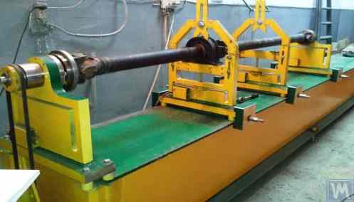
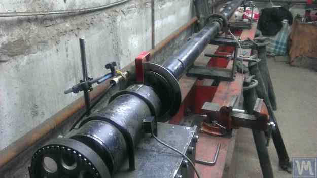
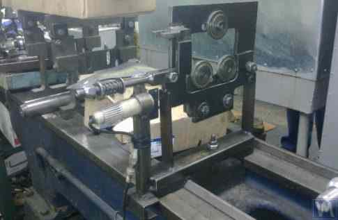
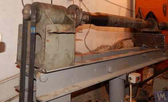
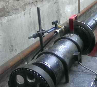
चित्र 2.4.a और 2.4.b ड्राइव शाफ्टों को संतुलित करने के लिए घर पर बनी एक सॉफ्ट बेयरिंग मशीन की तस्वीरें दिखाती हैं, जिसके सपोर्ट भी स्ट्रिप सस्पेंशन स्प्रिंग्स का उपयोग करके बनाए गए हैं।
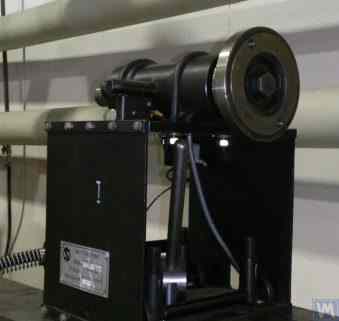
आकृति 2.5 यह तस्वीर टर्बोचार्जर को संतुलित करने के लिए डिज़ाइन की गई सॉफ्ट बेयरिंग मशीन को दर्शाती है, जिसके कैरिज के सपोर्ट भी स्ट्रिप स्प्रिंग पर लगे हुए हैं। सेंट पीटर्सबर्ग के ए. शाहगुनयान के निजी उपयोग के लिए बनाई गई यह मशीन "बैलेंसेट 1" मापन प्रणाली से सुसज्जित है।
निर्माता के अनुसार (देखें आकृति 2.6), यह मशीन टर्बाइनों को 0.2 g*mm से अधिक न होने वाले अवशिष्ट असंतुलन के साथ संतुलित करने की क्षमता प्रदान करती है।
चित्र 2.3. स्ट्रिप स्प्रिंग्स पर सपोर्ट सस्पेंशन के साथ उपकरणों के संतुलन के लिए सॉफ्ट बेयरिंग मशीन
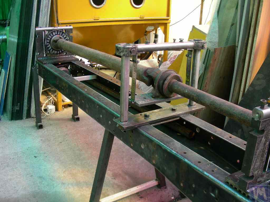
चित्र 2.4.a. ड्राइव शाफ्ट्स के संतुलन के लिए सॉफ्ट बेयरिंग मशीन (मशीन असेंबल्ड)
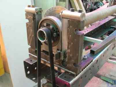
चित्र 2.4.b. स्ट्रिप स्प्रिंग्स पर लटके कैरिज सपोर्ट्स के साथ ड्राइव शाफ्ट्स को संतुलित करने के लिए सॉफ्ट बेयरिंग मशीन। (स्प्रिंग स्ट्रिप सस्पेंशन के साथ लीडिंग स्पिंडल सपोर्ट)
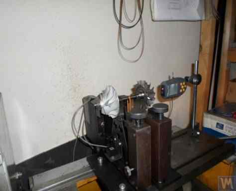
चित्र 2.5. स्ट्रिप स्प्रिंग्स पर समर्थित टर्बोचार्जरों के संतुलन के लिए सॉफ्ट बेयरिंग मशीन, निर्मित ए. शाहगुन्यान (सेंट पीटर्सबर्ग) द्वारा
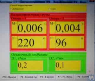
चित्र 2.6. ए. शाहगुनियान की मशीन पर टरबाइन रोटर बैलेंसिंग के परिणामों को दर्शाने वाले 'बैलेंससेट 1' मापन प्रणाली की स्क्रीन कॉपी।
ऊपर चर्चा किए गए सॉफ्ट बेयरिंग संतुलन मशीन के क्लासिक संस्करण के अलावा, अन्य संरचनात्मक समाधान भी व्यापक रूप से प्रचलित हो गए हैं।
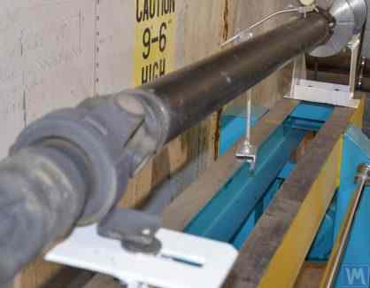
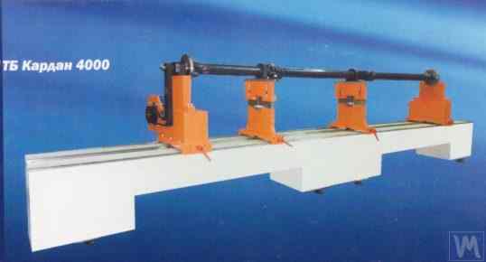
आकृति 2.7 और 2.8 ड्राइव शाफ्ट के लिए बैलेंसिंग मशीनों की तस्वीरें प्रदर्शित की गई हैं, जिनके सपोर्ट फ्लैट (प्लेट) स्प्रिंग पर आधारित हैं। ये मशीनें क्रमशः निजी उद्यम "डेर्गाचेवा" और एलएलसी "टैटकार्डन" ("काइनेटिक्स-एम") की निजी आवश्यकताओं के लिए निर्मित की गई थीं।
इस प्रकार के सपोर्ट वाली सॉफ्ट बेयरिंग बैलेंसिंग मशीनों को इनकी अपेक्षाकृत सरलता और निर्माण में आसानी के कारण शौकिया निर्माता अक्सर बनाते हैं। ये प्रोटोटाइप आमतौर पर या तो "के. शेंक" की वीबीआरएफ श्रृंखला की मशीनें होती हैं या इसी तरह की घरेलू स्तर पर निर्मित मशीनें होती हैं।
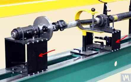
चित्र 2.7 और 2.8 में दिखाए गए मशीन दो-आधार, तीन-आधार और चार-आधार ड्राइव शाफ्टों के संतुलन के लिए डिज़ाइन किए गए हैं। इनका निर्माण समान है, जिसमें शामिल हैं:
- एक वेल्डेड बेडफ्रेम 1, जो दो आई-बीमों से बना है जिन्हें क्रॉस रिब्स द्वारा जोड़ा गया है;
- एक स्थिर (अग्र) स्पिंडल सपोर्ट 2;
- एक चलने वाला (पीछला) स्पिंडल सपोर्ट 3;
- एक या दो चलने योग्य (अंतरिम) समर्थन 4। समर्थन 2 और 3 मशीन पर संतुलित ड्राइव शाफ्ट 7 को स्थापित करने के लिए स्पिंडल इकाइयाँ 5 और 6 को धारण करते हैं।
चित्र 2.7. निजी उद्यम "डेर्गाचेवा" द्वारा निर्मित ड्राइव शाफ्ट को संतुलित करने वाली सॉफ्ट बेयरिंग मशीन, जिसमें फ्लैट (प्लेट) स्प्रिंग पर सपोर्ट लगे हैं।
चित्र 2.8. एलएलसी "टैटकार्डन" ("काइनेटिक्स-एम") द्वारा निर्मित ड्राइव शाफ्ट को संतुलित करने वाली सॉफ्ट बेयरिंग मशीन, जिसमें फ्लैट स्प्रिंग्स पर सपोर्ट लगे हैं।
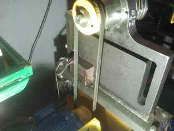
वाइब्रेशन सेंसर 8 सभी सपोर्ट्स पर स्थापित किए गए हैं, जिनका उपयोग सपोर्ट्स के अनुप्रस्थ दोलनों को मापने के लिए किया जाता है। अग्रणी स्पिंडल 5, जो सपोर्ट 2 पर स्थापित है, को बेल्ट ड्राइव के माध्यम से एक इलेक्ट्रिक मोटर द्वारा घुमाया जाता है।
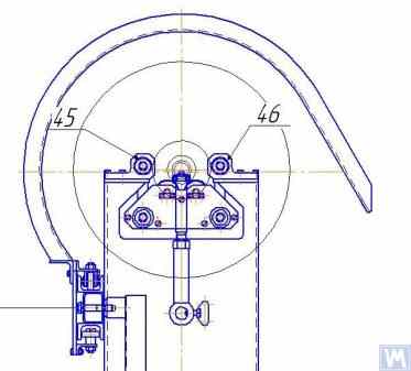
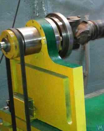
चित्र 2.9.क और 2.9.ख समतल स्प्रिंग्स पर आधारित संतुलन मशीन के सपोर्ट की तस्वीरें दिखाती हैं।
चित्र 2.9. सपाट स्प्रिंग्स के साथ सॉफ्ट बेयरिंग बैलेंसिंग मशीन सपोर्ट
- ख) पार्श्व दृश्य;
- ख) अग्रदृश्य
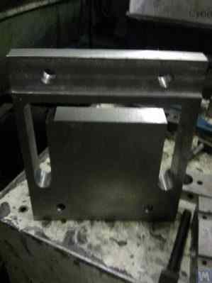
चूंकि शौकिया निर्माता अक्सर अपने डिज़ाइनों में इस प्रकार के समर्थन का उपयोग करते हैं, इसलिए उनके निर्माण की विशेषताओं की अधिक विस्तार से जांच करना उपयोगी है। जैसा कि चित्र 2.9.a में दिखाया गया है, यह समर्थन तीन मुख्य घटकों से मिलकर बना है:
- निचली समर्थन प्लेट 1: अग्र स्पिंडल समर्थन के लिए प्लेट गाइडों से दृढ़तापूर्वक जुड़ी होती है; मध्यवर्ती या पश्च स्पिंडल समर्थन के लिए निचली प्लेट को एक कैरिज के रूप में डिज़ाइन किया गया है जो फ्रेम गाइडों पर चल सकती है।
- ऊपरी समर्थन प्लेट 2, जिस पर समर्थन इकाइयाँ लगाई जाती हैं (रोलर सपोर्ट 4, स्पिंडल्स, मध्यवर्ती बेयरिंग्स, आदि)।
- दो समतल स्प्रिंग 3, निचली और ऊपरी बेयरिंग प्लेटों को जोड़ना।
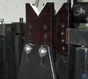
संचालन के दौरान, संतुलित रोटर के त्वरण या मंदी के समय, समर्थन संरचनाओं में कंपन बढ़ने के जोखिम को रोकने के लिए, समर्थन संरचनाओं में एक लॉकिंग तंत्र शामिल हो सकता है (देखें आकृति 2.9.b)। यह तंत्र एक कठोर ब्रैकेट 5 से बना है, जिसे समर्थन की समतल स्प्रिंग्स में से एक से जुड़े एक अपकेंद्रिय ताले 6 द्वारा संलग्न किया जा सकता है। जब ताला 6 और ब्रैकेट 5 संलग्न होते हैं, तो समर्थन लॉक हो जाता है, जिससे त्वरण और मंदी के दौरान कंपन बढ़ने का जोखिम समाप्त हो जाता है।
सपाट (प्लेट) स्प्रिंग्स से बने सपोर्ट्स को डिजाइन करते समय, मशीन निर्माता को उनकी प्राकृतिक दोलन आवृत्तियों का आकलन करना चाहिए, जो स्प्रिंग्स की कठोरता और संतुलित रोटर के द्रव्यमान पर निर्भर करती हैं। इस पैरामीटर को जानने से डिजाइनर को रोटर की परिचालन घूर्णी आवृत्तियों की सीमा को सचेत रूप से चुनने में मदद मिलती है, जिससे संतुलन के दौरान सपोर्ट्स के अनुनादी दोलनों का खतरा टल जाता है।
समर्थनों के दोलनों की प्राकृतिक आवृत्तियों की गणना करने और प्रायोगिक रूप से निर्धारित करने के लिए सिफारिशें, साथ ही संतुलन मशीनों के अन्य घटकों के लिए, अनुभाग 3 में चर्चा की गई हैं।
जैसा कि पहले उल्लेख किया गया है, फ्लैट (प्लेट) स्प्रिंग्स का उपयोग करके सपोर्ट डिज़ाइन की सादगी और निर्माण क्षमता विभिन्न उद्देश्यों के लिए संतुलन मशीनों के शौकिया विकासकर्ताओं को आकर्षित करती है, जिनमें क्रैंकशाफ्ट, ऑटोमोटिव टर्बोचार्जर रोटर आदि के संतुलन के लिए मशीनें शामिल हैं।
उदाहरण के तौर पर, चित्र 2.10.a और 2.10.b में टर्बोचार्जर रोटर्स को संतुलित करने के लिए डिज़ाइन की गई मशीन का एक सामान्य दृश्य रेखाचित्र प्रस्तुत किया गया है। यह मशीन पेन्ज़ा स्थित एलएलसी "सूराटर्बो" में निर्मित है और वहीं आंतरिक आवश्यकताओं के लिए उपयोग की जाती है।
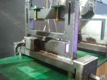
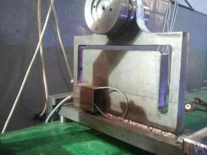
2.10.a. टर्बोचार्जर रोटरों को संतुलित करने की मशीन (साइड व्यू)
2.10.b. टर्बोचार्जर रोटरों के संतुलन के लिए मशीन (सामने के सपोर्ट साइड से दृश्य)
पहले चर्चा की गई सॉफ्ट बेयरिंग संतुलन मशीनों के अलावा, अपेक्षाकृत सरल सॉफ्ट बेयरिंग स्टैंड कभी-कभी बनाए जाते हैं। ये स्टैंड न्यूनतम लागत में विभिन्न उद्देश्यों के लिए घूर्णन तंत्रों का उच्च-गुणवत्ता संतुलन संभव बनाते हैं।
नीचे ऐसे कई स्टैंडों की समीक्षा की गई है, जो बेलनाकार संपीड़न स्प्रिंगों पर टिकी एक सपाट प्लेट (या फ्रेम) के आधार पर निर्मित हैं। इन स्प्रिंगों का चयन आमतौर पर इस प्रकार किया जाता है कि संतुलन तंत्र स्थापित प्लेट के दोलनों की प्राकृतिक आवृत्ति, संतुलन के दौरान इस तंत्र के रोटर की घूर्णन आवृत्ति से 2 से 3 गुना कम हो।
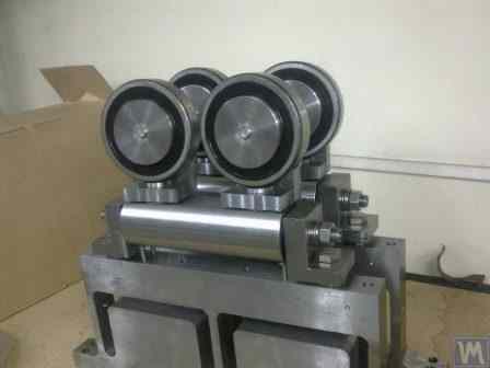
आकृति 2.11 पी. अश्रिन द्वारा इन-हाउस उत्पादन के लिए निर्मित, घर्षण पहियों को संतुलित करने वाले एक स्टैंड की तस्वीर दिखाता है।
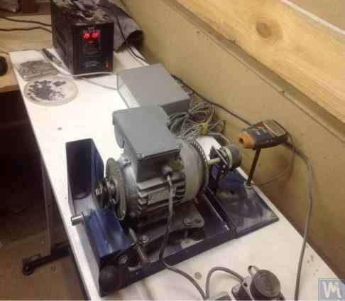
चित्र 2.11. घर्षक पहियों को संतुलित करने के लिए स्टैंड
स्टैंड में निम्नलिखित मुख्य घटक शामिल हैं:
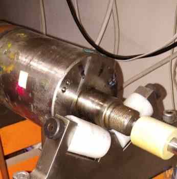
- प्लेट 1, चार बेलनाकार स्प्रिंग्स 2 पर लगा हुआ;
- विद्युत मोटर 3, जिसका रोटर स्पिंडल के रूप में भी काम करता है, जिस पर एक मैंड्रेल 4 लगाया जाता है, जिसका उपयोग स्पिंडल पर घिसाई पहिया को स्थापित करने और सुरक्षित करने के लिए किया जाता है।
इस स्टैंड की एक प्रमुख विशेषता इलेक्ट्रिक मोटर के रोटर के घूर्णन कोण के लिए पल्स सेंसर 5 का समावेश है, जिसका उपयोग स्टैंड ("बैलेंसेट 2सी") की मापन प्रणाली के हिस्से के रूप में अपघर्षक पहिया से सुधारात्मक द्रव्यमान को हटाने के लिए कोणीय स्थिति निर्धारित करने के लिए किया जाता है।
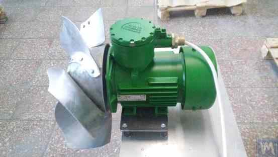
आकृति 2.12 यह तस्वीर वैक्यूम पंपों को संतुलित करने के लिए उपयोग किए जाने वाले स्टैंड को दर्शाती है। इस स्टैंड को जेएससी "मेजरमेंट प्लांट" द्वारा ऑर्डर पर विकसित किया गया था।
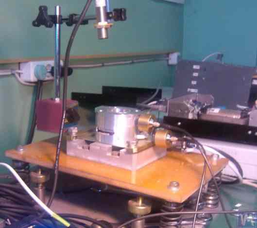
चित्र 2.12. जेएससी "मापन संयंत्र" द्वारा निर्मित वैक्यूम पंपों के संतुलन के लिए स्टैंड।"
इस स्टैंड के आधार में भी प्लेट 1, बेलनाकार स्प्रिंग्स 2 पर स्थापित। प्लेट 1 पर एक वैक्यूम पंप 3 स्थापित है, जिसमें 0 से 60,000 आरपीएम तक गति को व्यापक रूप से बदलने में सक्षम अपना स्वयं का इलेक्ट्रिक ड्राइव है। कंपन सेंसर 4 पंप के आवरण पर स्थापित हैं, जिनका उपयोग विभिन्न ऊँचाइयों पर दो अलग-अलग खंडों में कंपन मापने के लिए किया जाता है।
पंप रोटर के घूर्णन कोण के साथ कंपन मापन प्रक्रिया के सिंक्रनाइज़ेशन के लिए, स्टैंड पर लेजर फेज एंगल सेंसर 5 का उपयोग किया जाता है। ऐसे स्टैंड की बाहरी संरचना देखने में सरल लगती है, लेकिन यह पंप के इम्पेलर का बहुत उच्च गुणवत्ता वाला संतुलन प्राप्त करने में सक्षम बनाता है।
उदाहरण के लिए, sub-critical rotational frequencies पर pump rotor का residual imbalance ISO 21940-11 (पूर्व में ISO 1940-1) में परिभाषित सबसे सूक्ष्म balance quality grade G0.4 की tolerance से नीचे है — एक in-house bench result जो notional G0.16 के समतुल्य है, जो standard में सूचीबद्ध किसी भी grade से अधिक कड़ा है।
8,000 आरपीएम तक की घूर्णी गति पर संतुलन के दौरान पंप केसिंग में उत्पन्न अवशिष्ट कंपन 0.01 मिमी/सेकंड से अधिक नहीं होता।
उपरोक्त वर्णित योजना के अनुसार निर्मित संतुलन स्टैंड अन्य यंत्रों, जैसे पंखों, के संतुलन में भी प्रभावी होते हैं। पंखों के संतुलन के लिए डिज़ाइन किए गए स्टैंड के उदाहरण चित्र 2.13 और 2.14 में दिखाए गए हैं।
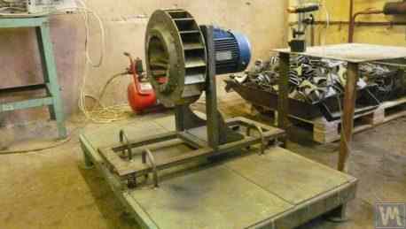
चित्र 2.13. पंखे के इम्पेलरों को संतुलित करने के लिए स्टैंड
ऐसे स्टैंड पर पंखों का संतुलन काफी उच्च गुणवत्ता का होता है। "अटलांट-प्रोजेक्ट" एलएलसी के विशेषज्ञों के अनुसार, "काइनेमेटिक्स" एलएलसी की सिफारिशों के आधार पर उनके द्वारा डिजाइन किए गए स्टैंड (चित्र 2.14 देखें) पर पंखों का संतुलन करते समय अवशिष्ट कंपन का स्तर 0.8 मिमी/सेकंड प्राप्त हुआ। यह आईएसओ 31350-2007 "कंपन। औद्योगिक पंखे। उत्पादित कंपन और संतुलन गुणवत्ता के लिए आवश्यकताएँ" के अनुसार श्रेणी बीवी5 के पंखों के लिए निर्धारित सहनशीलता से तीन गुना से भी अधिक बेहतर है।"
चित्र 2.14. पोडोलस्क स्थित "अटलांट-प्रोजेक्ट" एलएलसी द्वारा निर्मित विस्फोट-रोधी उपकरणों के लिए पंखे के इम्पेलर को संतुलित करने वाला स्टैंड।
जेएससी "लिसांट फैन फैक्ट्री" में प्राप्त समान आंकड़ों से पता चलता है कि डक्ट पंखों के सीरियल उत्पादन में उपयोग किए जाने वाले ऐसे स्टैंड लगातार 0.1 मिमी/सेकंड से अधिक अवशिष्ट कंपन सुनिश्चित नहीं करते हैं।
2.2. हार्ड बेयरिंग मशीनें
हार्ड बेयरिंग संतुलन मशीनें पहले चर्चा की गई सॉफ्ट बेयरिंग मशीनों से उनके समर्थन के डिज़ाइन में भिन्न होती हैं। उनके समर्थन जटिल स्लॉट (कट-आउट) वाली कठोर प्लेटों के रूप में बनाए जाते हैं। इन समर्थन की प्राकृतिक आवृत्तियाँ मशीन पर संतुलित रोटर की अधिकतम घूर्णी आवृत्ति से काफी (कम से कम 2-3 गुना) अधिक होती हैं।
हार्ड बेयरिंग मशीनें सॉफ्ट बेयरिंग मशीनों की तुलना में अधिक बहुमुखी होती हैं, क्योंकि ये आमतौर पर रोटरों के द्रव्यमान और आयामी विशेषताओं की व्यापक श्रेणी में उच्च-गुणवत्ता वाला संतुलन करने की अनुमति देती हैं। इन मशीनों का एक महत्वपूर्ण लाभ यह भी है कि ये अपेक्षाकृत कम घूर्णी गति पर रोटरों का उच्च-सटीक संतुलन संभव बनाती हैं, जो 200–500 आरपीएम या उससे कम की सीमा में हो सकती है।
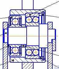
आकृति 2.15 चित्र में "के. शेंक" द्वारा निर्मित एक विशिष्ट हार्ड बेयरिंग बैलेंसिंग मशीन का चित्र दिखाया गया है। इस चित्र से स्पष्ट है कि जटिल खांचों से बने सपोर्ट के अलग-अलग हिस्सों की कठोरता भिन्न-भिन्न है। रोटर असंतुलन के बलों के प्रभाव में, सपोर्ट के कुछ हिस्सों में अन्य हिस्सों की तुलना में विकृति (विस्थापन) हो सकती है। (चित्र 2.15 में, सपोर्ट के अधिक कठोर भाग को लाल बिंदीदार रेखा से दर्शाया गया है, और इसके अपेक्षाकृत लचीले भाग को नीले रंग में दिखाया गया है)।
उक्त सापेक्ष विकृतियों को मापने के लिए हार्ड बेयरिंग मशीनें या तो बल संवेदकों का उपयोग कर सकती हैं या विभिन्न प्रकार के अत्यधिक संवेदनशील कंपन संवेदकों का, जिनमें गैर-संपर्क कंपन विस्थापन संवेदक भी शामिल हैं।
चित्र 2.15. "के. शेंक" द्वारा निर्मित हार्ड बेयरिंग बैलेंसिंग मशीन"
"बैलेंसेट" श्रृंखला के उपकरणों के लिए ग्राहकों से प्राप्त अनुरोधों के विश्लेषण से पता चलता है कि आंतरिक उपयोग के लिए हार्ड बेयरिंग मशीनों के निर्माण में रुचि लगातार बढ़ रही है। घरेलू बैलेंसिंग मशीनों की डिज़ाइन विशेषताओं के बारे में विज्ञापन संबंधी जानकारी के व्यापक प्रसार से इसमें मदद मिली है, जिनका उपयोग शौकिया निर्माता अपने स्वयं के विकास के लिए एनालॉग (या प्रोटोटाइप) के रूप में करते हैं।
आइए "बैलेंसेट" श्रृंखला के उपकरणों के कई उपभोक्ताओं की आंतरिक आवश्यकताओं के लिए निर्मित हार्ड बेयरिंग मशीनों के कुछ प्रकारों पर विचार करें।
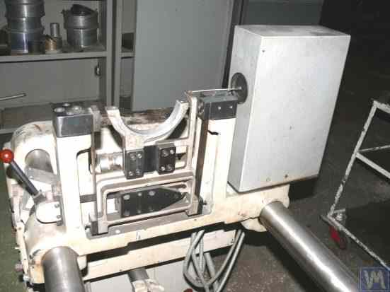
चित्र 2.16.a – 2.16.d चित्र में ड्राइव शाफ्ट को संतुलित करने के लिए डिज़ाइन की गई हार्ड बेयरिंग मशीन की तस्वीरें दिखाई गई हैं, जिसका निर्माण एन. ओब्येदकोव (मैग्निटोगोर्स्क शहर) द्वारा किया गया था। जैसा कि चित्र 2.16.a में देखा जा सकता है, मशीन में एक कठोर फ्रेम 1 होता है, जिस पर सपोर्ट 2 (दो स्पिंडल और दो मध्यवर्ती) लगे होते हैं। मशीन का मुख्य स्पिंडल 3 एक बेल्ट ड्राइव के माध्यम से एक अतुल्यकालिक विद्युत मोटर 4 द्वारा घुमाया जाता है। विद्युत मोटर 4 की घूर्णन गति को नियंत्रित करने के लिए एक आवृत्ति नियंत्रक 6 का उपयोग किया जाता है। मशीन "बैलेंससेट 4" मापन और गणना प्रणाली 5 से सुसज्जित है, जिसमें एक मापन इकाई, एक कंप्यूटर, चार बल सेंसर और एक फेज एंगल सेंसर शामिल हैं (सेंसर चित्र 2.16.a में नहीं दिखाए गए हैं)।
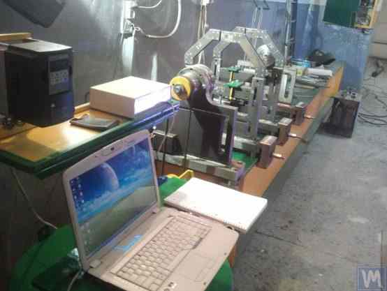
चित्र 2.16.a. ड्राइव शाफ्टों को संतुलित करने के लिए कठोर बेयरिंग मशीन, एन. ओब्येदकोव (मैग्नीटोगोर्स्क) द्वारा निर्मित
आकृति 2.16.ख यह मशीन के अग्रभाग के समर्थन की एक तस्वीर दिखाता है, जिसमें अग्रणी स्पिंडल 3 है, जिसे, जैसा कि पहले उल्लेख किया गया है, असिंक्रोनस इलेक्ट्रिक मोटर 4 से बेल्ट ड्राइव द्वारा संचालित किया जाता है। यह समर्थन फ्रेम पर दृढ़ता से स्थापित है।
आकृति 2.16.b. अग्र (लीडिंग) स्पिंडल सपोर्ट।
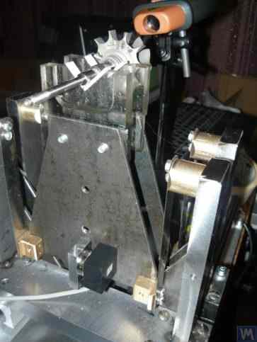
आकृति 2.16.c यह मशीन के दो चलने योग्य मध्यवर्ती समर्थन में से एक की तस्वीर दिखाता है। यह समर्थन स्लाइड्स 7 पर टिका होता है, जिससे यह फ्रेम गाइड्स के साथ अपनी लंबवत दिशा में गति कर सकता है। इस समर्थन में एक विशेष उपकरण 8 शामिल है, जिसे संतुलित ड्राइव शाफ्ट के मध्यवर्ती बेयरिंग की ऊँचाई स्थापित करने और समायोजित करने के लिए डिज़ाइन किया गया है।
चित्र 2.16.c. मशीन का मध्यवर्ती चल समर्थक
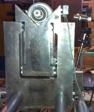
आकृति 2.16.d इसमें पीछे वाले (चालित) स्पिंडल सपोर्ट की एक तस्वीर दिखाई गई है, जो मध्यवर्ती सपोर्ट की तरह, मशीन फ्रेम के गाइड के साथ गति की अनुमति देता है।
आकृति 2.16.d. पिछला (चालित) स्पिंडल समर्थन।
ऊपर चर्चा किए गए सभी समर्थन क्षैतिज आधारों पर स्थापित ऊर्ध्वाधर प्लेटें हैं। इन प्लेटों में टी-आकार की स्लॉट्स (देखें आकृति 2.16.d) होती हैं, जो समर्थन को आंतरिक भाग 9 (अधिक कठोर) और बाहरी भाग 10 (कम कठोर) में विभाजित करती हैं। समर्थन के आंतरिक और बाहरी भागों की भिन्न कठोरता संतुलित रोटर से उत्पन्न असंतुलन बलों के प्रभाव में इन भागों के सापेक्ष विरूपण का कारण बन सकती है।
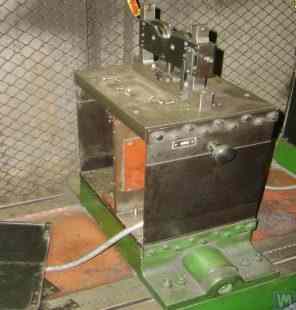
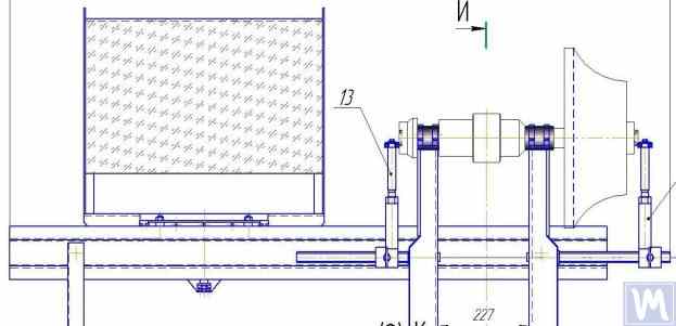
फोर्स सेंसर आमतौर पर घर पर बनी मशीनों में सहाराओं के सापेक्ष विकृति को मापने के लिए उपयोग किए जाते हैं। फोर्स सेंसर को हार्ड बेयरिंग बैलेंसिंग मशीन के सहारा पर कैसे स्थापित किया जाता है, इसका एक उदाहरण चित्र 2.16.e में दिखाया गया है। जैसा कि इस चित्र में देखा जा सकता है, फोर्स सेंसर 11 को एक बोल्ट 12 द्वारा सहारा के आंतरिक भाग की पार्श्व सतह पर दबाया जाता है, जो सहारा के बाहरी भाग में स्थित थ्रेडेड छेद से होकर गुजरता है।
बोल्ट 12 के पूरे फोर्स सेंसर 11 के तल पर समान दबाव सुनिश्चित करने के लिए, इसके और सेंसर के बीच एक फ्लैट वाशर 13 रखा जाता है।
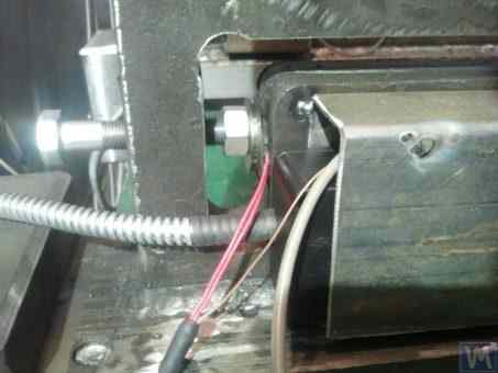
चित्र 2.16.d. एक सहारे पर फोर्स सेंसर की स्थापना का उदाहरण।
मशीन के संचालन के दौरान, संतुलित रोटर से उत्पन्न असंतुलन बल, सपोर्ट इकाइयों (स्पिंडल या मध्यवर्ती बियरिंग) के माध्यम से सपोर्ट के बाहरी भाग पर कार्य करते हैं, जिससे बाहरी भाग रोटर के घूर्णन की आवृत्ति पर अपने आंतरिक भाग के सापेक्ष चक्रीय रूप से गतिमान (विकृत) होने लगता है। इसके परिणामस्वरूप, सेंसर 11 पर एक परिवर्तनशील बल कार्य करता है, जो असंतुलन बल के समानुपाती होता है। इसके प्रभाव से, बल सेंसर के आउटपुट पर रोटर के असंतुलन के परिमाण के समानुपाती एक विद्युत संकेत उत्पन्न होता है।
सभी सपोर्टों पर लगे फोर्स सेंसर से प्राप्त सिग्नल मशीन के मापन और गणना प्रणाली में भेजे जाते हैं, जहां उनका उपयोग सुधारात्मक भार के मापदंडों को निर्धारित करने के लिए किया जाता है।
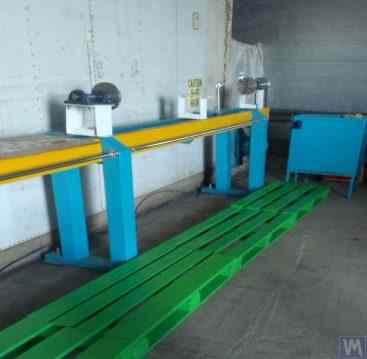
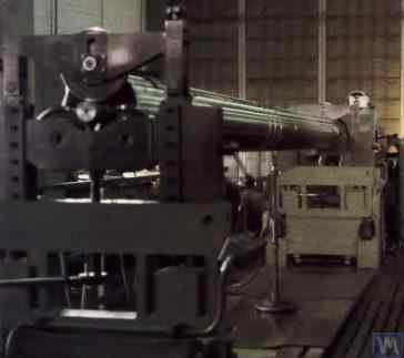
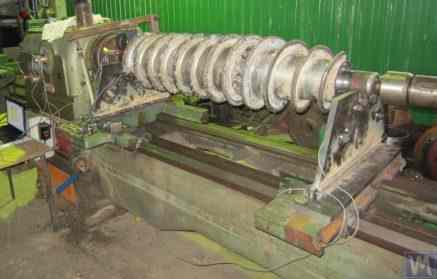
आकृति 2.17.a. इसमें स्क्रू शाफ्ट को संतुलित करने के लिए उपयोग की जाने वाली एक विशेष हार्ड बेयरिंग मशीन की तस्वीर दिखाई गई है। यह मशीन एलएलसी "उफातवरदोस्प्लाव" में आंतरिक उपयोग के लिए निर्मित की गई थी।
चित्र में दिखाए अनुसार, मशीन के स्पिन-अप तंत्र का निर्माण सरलीकृत है, जिसमें निम्नलिखित मुख्य घटक शामिल हैं:
- वेल्डेड फ्रेम 1, बिस्तर के रूप में काम करते हुए;
- दो स्थिर सहारे 2, फ्रेम से कसकर जड़ा हुआ;
- विद्युत मोटर 3, जो बेल्ट ड्राइव 4 के माध्यम से संतुलित शाफ्ट (स्क्रू) 5 को घुमाता है।
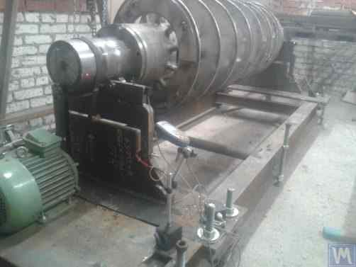
चित्र 2.17.a. स्क्रू शाफ्ट को संतुलित करने के लिए हार्ड बेयरिंग मशीन, एलएलसी "उफातवेरदोस्प्लाव" द्वारा निर्मित।"
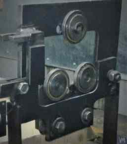
मशीन के दो समर्थन ऊर्ध्वाधर रूप से स्थापित स्टील प्लेटें हैं जिनमें टी-आकार के स्लॉट होते हैं। प्रत्येक समर्थन के शीर्ष पर रोलिंग बेयरिंग्स का उपयोग करके निर्मित समर्थन रोलर्स होते हैं, जिन पर संतुलित शाफ्ट 5 घूमता है।
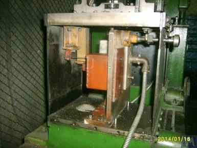
रोटर असंतुलन के कारण उत्पन्न होने वाले सपोर्ट के विरूपण को मापने के लिए, सपोर्ट के खांचों में बल सेंसर 6 (चित्र 2.17.b देखें) लगाए जाते हैं। ये सेंसर "बैलेंससेट 1" उपकरण से जुड़े होते हैं, जिसका उपयोग इस मशीन पर मापन और गणना प्रणाली के रूप में किया जाता है।
मशीन के स्पिन-अप तंत्र की सापेक्षिक सरलता के बावजूद, यह पेंचों के पर्याप्त उच्च-गुणवत्ता वाले संतुलन को सक्षम बनाता है, जैसा कि चित्र 2.17.ए में देखा गया है, जिसमें एक जटिल पेचदार सतह होती है।
एलएलसी "उफातवेरदोस्प्लाव" के अनुसार, इस मशीन पर संतुलन प्रक्रिया के दौरान पेंच का प्रारंभिक असंतुलन लगभग 50 गुना कम हो गया था।
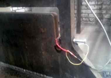
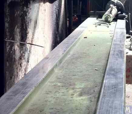
चित्र 2.17.b. बल संवेदक के साथ स्क्रू शाफ्टों को संतुलित करने के लिए हार्ड बेयरिंग मशीन सपोर्ट
प्राप्त residual imbalance screw के first plane में 3552 g*mm (185 mm radius पर 19.2 g) और second plane में 2220 g*mm (185 mm radius पर 12.0 g) था। 500 kg वजन वाले और 3500 RPM rotational frequency पर operating rotor के लिए यह imbalance ISO 21940-11 (पूर्व में ISO 1940-1) के अनुसार class G6.3 से मेल खाता है, जो उसके technical documentation में निर्धारित requirements को पूरा करता है।
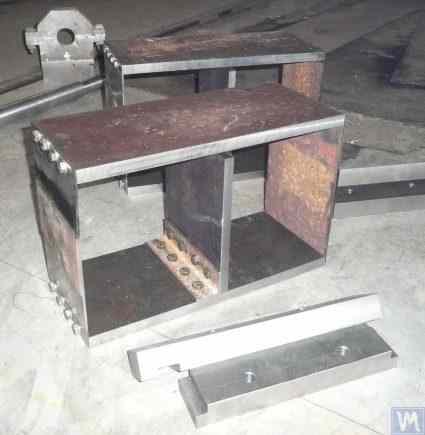
एस.वी. मोरोज़ोव द्वारा एक मौलिक डिज़ाइन (चित्र 2.18 देखें) प्रस्तावित किया गया था, जिसमें अलग-अलग आकार की दो हार्ड बेयरिंग बैलेंसिंग मशीनों के लिए एक साथ सपोर्ट लगाने हेतु एक ही आधार का उपयोग किया जाता है। इस तकनीकी समाधान के स्पष्ट लाभ, जो निर्माता की उत्पादन लागत को कम करने में सहायक हैं, इस प्रकार हैं:
- उत्पादन स्थान की बचत;
- दो अलग-अलग मशीनों को चलाने के लिए एक इलेक्ट्रिक मोटर का उपयोग एक परिवर्तनीय आवृत्ति ड्राइव के साथ;
- दो अलग-अलग मशीनों को चलाने के लिए एक मापन प्रणाली का उपयोग।

चित्र 2.18. हार्ड बेयरिंग बैलेंसिंग मशीन ("टैंडम"), एस.वी. मोरोज़ोव द्वारा निर्मित
3. संतुलन मशीनों के मूल इकाइयों और तंत्रों के निर्माण के लिए आवश्यकताएँ
3.1. बेयरिंग्स
3.1.1. बियरिंग डिजाइन के सैद्धांतिक आधार
पिछले खंड में, संतुलन मशीनों के लिए सॉफ्ट बेयरिंग और हार्ड बेयरिंग सपोर्ट के मुख्य डिज़ाइन निष्पादन पर विस्तार से चर्चा की गई थी। इन सपोर्टों के डिज़ाइन और निर्माण के दौरान डिज़ाइनरों को जिन महत्वपूर्ण मापदंडों पर विचार करना चाहिए, उनमें से एक है उनकी दोलन की प्राकृतिक आवृत्तियाँ। यह महत्वपूर्ण है क्योंकि मशीन के मापन और गणना प्रणालियों द्वारा सुधारात्मक भार के मापदंडों की गणना के लिए सपोर्टों के कंपन (चक्रीय विरूपण) के आयाम के साथ-साथ कंपन की अवस्था का मापन भी आवश्यक है।
यदि किसी आधार की प्राकृतिक आवृत्ति संतुलित रोटर की घूर्णन आवृत्ति के साथ मेल खाती है (आधार अनुनाद), तो कंपन के आयाम और चरण का सटीक मापन व्यावहारिक रूप से असंभव है। संतुलित रोटर की घूर्णन आवृत्ति के फलन के रूप में आधार के दोलनों के आयाम और चरण में परिवर्तन दर्शाने वाले ग्राफ़ में यह स्पष्ट रूप से प्रदर्शित होता है (चित्र 3.1 देखें)।
इन ग्राफ़ों से यह निष्कर्ष निकलता है कि जैसे-जैसे संतुलित रोटर की घूर्णी आवृत्ति समर्थन दोलनों की प्राकृतिक आवृत्ति के निकट पहुँचती है (यानी, जब fp/fo का अनुपात 1 के करीब होता है), समर्थन के अनुनाद दोलनों से संबंधित आयाम में एक महत्वपूर्ण वृद्धि होती है (देखें आकृति 3.1.a)। साथ ही, ग्राफ़ 3.1.b दर्शाता है कि अनुनाद क्षेत्र में, फेज कोण ∆F° में तीव्र परिवर्तन होता है, जो 180° तक पहुँच सकता है।
दूसरे शब्दों में, जब किसी तंत्र को अनुनाद क्षेत्र में संतुलित किया जाता है, तो इसके घूर्णन आवृत्ति में मामूली परिवर्तन भी इसके कम्पन आयाम और चरण के मापन परिणामों में महत्वपूर्ण अस्थिरता (माप-अस्थिरता) पैदा कर सकते हैं, जिससे सुधारात्मक भारों के पैरामीटरों की गणना में त्रुटियाँ होती हैं और संतुलन (बैलेंसिंग) की गुणवत्ता पर नकारात्मक प्रभाव पड़ता है।
उपरोक्त ग्राफ पहले की सिफारिशों की पुष्टि करते हैं कि हार्ड बेयरिंग मशीनों के लिए, रोटर की परिचालन आवृत्तियों की ऊपरी सीमा सपोर्ट की प्राकृतिक आवृत्ति, fo, से (कम से कम) 2-3 गुना कम होनी चाहिए। सॉफ्ट बेयरिंग मशीनों के लिए, संतुलित रोटर की अनुमेय परिचालन आवृत्तियों की निचली सीमा सपोर्ट की प्राकृतिक आवृत्ति से (कम से कम) 2-3 गुना अधिक होनी चाहिए।
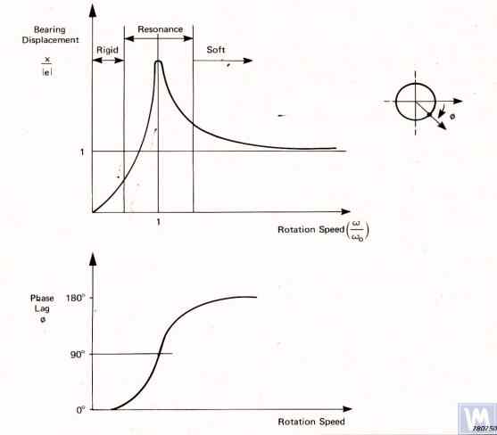
चित्र 3.1. घूर्णी आवृत्ति में परिवर्तनों के फलस्वरूप संतुलन मशीन के समर्थन के कम्पन के सापेक्ष आयाम और चरण में होने वाले परिवर्तनों को दर्शाने वाले ग्राफ़।
- Ад – समर्थन की गतिशील कम्पनों का आयाम;
- e = m*r / M - संतुलित रोटर का विशिष्ट असंतुलन;
- एम – रोटर का असंतुलित द्रव्यमान;
- M – रोटर का द्रव्यमान;
- r – वह त्रिज्या जिस पर रोटर पर असंतुलित द्रव्यमान स्थित है;
- fp – रोटर की घूर्णन आवृत्ति;
- fo – समर्थन की कंपनों की प्राकृतिक आवृत्ति
प्रस्तुत जानकारी के आधार पर, मशीन को उसके समर्थन के अनुनाद क्षेत्र (चित्र 3.1 में लाल रंग से हाइलाइट किया गया) में संचालित करना अनुशंसित नहीं है। चित्र 3.1 में दिखाए गए ग्राफ़ यह भी दर्शाते हैं कि रोटर के समान असंतुलनों के लिए, सॉफ्ट बेयरिंग मशीन के समर्थन पर वास्तविक कंपन सामान्य बेयरिंग मशीन के समर्थन पर होने वाले कंपन की तुलना में काफी कम हैं।
इससे यह निष्कर्ष निकलता है कि हार्ड बेयरिंग मशीनों में समर्थन की कंपन मापने के लिए उपयोग किए जाने वाले सेंसरों की संवेदनशीलता सॉफ्ट बेयरिंग मशीनों में प्रयुक्त सेंसरों की तुलना में अधिक होनी चाहिए। यह निष्कर्ष सेंसरों के वास्तविक उपयोग के अनुभव से भी अच्छी तरह समर्थित है, जो दिखाता है कि सॉफ्ट बेयरिंग संतुलन मशीनों में सफलतापूर्वक उपयोग किए गए पूर्ण कंपन सेंसर (वाइब्रो-एक्सेलेरोमीटर और/या वाइब्रो-वेलोसिटी सेंसर) अक्सर हार्ड बेयरिंग मशीनों पर आवश्यक संतुलन गुणवत्ता प्राप्त नहीं कर पाते।
इन मशीनों पर सापेक्ष कंपन सेंसर, जैसे कि बल सेंसर या अत्यधिक संवेदनशील विस्थापन सेंसर का उपयोग करने की अनुशंसा की जाती है।
3.1.2. गणना विधियों का उपयोग करके सपोर्ट की प्राकृतिक आवृत्तियों का अनुमान
एक डिज़ाइनर सूत्र 3.1 का उपयोग करके एक समर्थन फो के प्राकृतिक आवृत्ति का अनुमानित (अनुमानात्मक) गणन कर सकता है, इसे सरलीकृत रूप से एक स्वतंत्रता के साथ एक कम्पन प्रणाली मानकर, जो (देखें आकृति 2.19.a) एक द्रव्यमान M द्वारा दर्शाई जाती है, जो कठोरता K वाली एक स्प्रिंग पर दोलन कर रहा है।
समतल अंतर-बेयरिंग रोटर के लिए गणना में प्रयुक्त द्रव्यमान को सूत्र 3.2 द्वारा अनुमानित किया जा सकता है।
जहां Mo सपोर्ट के गतिशील भाग का द्रव्यमान (किलोग्राम में) है; Mr संतुलित रोटर का द्रव्यमान (किलोग्राम में) है; n संतुलन में शामिल मशीन सपोर्ट की संख्या है।
समर्थन की कठोरता K का मान सूत्र 3.3 का उपयोग करके गणना किया जाता है, जो उन प्रयोगात्मक अध्ययनों के परिणामों पर आधारित है जिनमें स्थैतिक बल P से भारित होने पर समर्थन की विकृति ΔL को मापा जाता है (देखें आकृतियाँ 3.2.a और 3.2.b)।
जहां ΔL मीटर में आधार का विरूपण है; P न्यूटन में स्थैतिक बल है।
लोडिंग बल P की परिमाण को बल मापने वाले उपकरण (जैसे डायनामोमीटर) का उपयोग करके मापा जा सकता है। समर्थन की विस्थापन ΔL को रैखिक विस्थापन मापने वाले उपकरण (जैसे डायल इंडिकेटर) का उपयोग करके निर्धारित किया जाता है।
3.1.3. सपोर्ट की प्राकृतिक आवृत्तियों का निर्धारण करने के लिए प्रयोगात्मक विधियाँ
सपोर्ट की प्राकृतिक आवृत्तियों की गणना के लिए ऊपर बताई गई सरल विधि से महत्वपूर्ण त्रुटियाँ हो सकती हैं, इसलिए अधिकांश शौकिया डेवलपर इन मापदंडों को प्रायोगिक विधियों से निर्धारित करना पसंद करते हैं। इसके लिए वे आधुनिक कंपन मापन प्रणालियों, जैसे कि "बैलेंसेट" श्रृंखला के उपकरणों, की क्षमताओं का उपयोग करते हैं।
3.1.3.1. इम्पैक्ट एक्साइटेशन विधि द्वारा सहाराओं की प्राकृतिक आवृत्तियों का निर्धारण
इम्पैक्ट एक्सिटेशन विधि किसी सहारे या किसी अन्य मशीन घटक के कम्पन की प्राकृतिक आवृत्ति निर्धारित करने का सबसे सरल और सबसे सामान्य तरीका है। यह इस तथ्य पर आधारित है कि जब किसी वस्तु, जैसे कि घंटी (देखें आकृति 3.3), को इम्पैक्ट-एक्सिटेड किया जाता है, तो उसकी प्रतिक्रिया एक धीरे-धीरे क्षीण होती हुई कम्पन प्रतिक्रिया के रूप में प्रकट होती है। कंपन संकेत की आवृत्ति वस्तु की संरचनात्मक विशेषताओं द्वारा निर्धारित होती है और इसकी प्राकृतिक कम्पन आवृत्ति के अनुरूप होती है। कम्पन को आघात-उत्तेजित करने के लिए किसी भी भारी उपकरण का उपयोग किया जा सकता है, जैसे रबर का हथौड़ा या साधारण हथौड़ा।
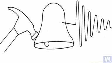
आकृति 3.3. किसी वस्तु की प्राकृतिक आवृत्तियों का निर्धारण करने के लिए प्रयुक्त प्रभाव उत्तेजना का आरेख
हथौड़े का द्रव्यमान उत्तेजित किए जा रहे वस्तु के द्रव्यमान का लगभग 10% होना चाहिए। कम्पन प्रतिक्रिया को पकड़ने के लिए, परीक्षण के अधीन वस्तु पर एक कम्पन सेंसर स्थापित किया जाना चाहिए, जिसका मापन अक्ष प्रहार उत्तेजना की दिशा के अनुरूप हो। कुछ मामलों में, शोर मापन यंत्र के माइक्रोफोन को वस्तु की कम्पन प्रतिक्रिया को महसूस करने के लिए सेंसर के रूप में उपयोग किया जा सकता है।
वस्तु के कंपन को सेंसर द्वारा विद्युत संकेत में परिवर्तित किया जाता है, जिसे बाद में स्पेक्ट्रम विश्लेषक जैसे मापन उपकरण के इनपुट में भेजा जाता है। यह उपकरण क्षीण होते कंपन की समय फलन और स्पेक्ट्रम को रिकॉर्ड करता है (चित्र 3.4 देखें), जिसके विश्लेषण से वस्तु के प्राकृतिक कंपन की आवृत्ति (आवृत्तियों) का निर्धारण किया जा सकता है।

चित्र 3.5. प्रोग्राम इंटरफ़ेस जो समय-कार्य ग्राफ़ और परीक्षण किए गए ढांचे के क्षयशील प्रभाव कम्पन का स्पेक्ट्रम दिखाता है।
चित्र 3.5 में प्रस्तुत स्पेक्ट्रम ग्राफ़ का विश्लेषण (कार्य विंडो के निचले भाग को देखें) दर्शाता है कि परीक्षण किए गए संरचना की प्राकृतिक कंपासनों का मुख्य घटक, जिसे ग्राफ़ के अक्ष (अब्स्किसिस् अक्ष) के संदर्भ में निर्धारित किया गया है, 9.5 हर्ट्ज़ की आवृत्ति पर होता है। इस विधि को सॉफ्ट बेयरिंग और हार्ड बेयरिंग संतुलन मशीन समर्थनों की प्राकृतिक कंपासनों के अध्ययन के लिए अनुशंसित किया जा सकता है।
3.1.3.2. कोस्टिंग मोड में सपोर्ट की प्राकृतिक आवृत्तियों का निर्धारण
कुछ मामलों में, सहारे की प्राकृतिक आवृत्तियों को "तटस्थ" कंपन के आयाम और चरण को चक्रीय रूप से मापकर निर्धारित किया जा सकता है। इस विधि को लागू करने में, जांच की जा रही मशीन पर लगे रोटर को पहले उसकी अधिकतम घूर्णन गति तक त्वरित किया जाता है, जिसके बाद उसका ड्राइव डिस्कनेक्ट कर दिया जाता है, और रोटर के असंतुलन से जुड़े विक्षोभ बल की आवृत्ति अधिकतम से धीरे-धीरे रुकने के बिंदु तक कम हो जाती है।
इस मामले में, समर्थकों की प्राकृतिक आवृत्तियाँ दो विशेषताओं द्वारा निर्धारित की जा सकती हैं:
- प्रतिध्वनि क्षेत्रों में देखी गई कम्पन आयाम में स्थानीय उछाल द्वारा;
- एम्प्लिट्यूड जंप के क्षेत्र में देखी गई कम्पन अवस्था में एक तीव्र परिवर्तन (180° तक)।
"बैलेंसेट" श्रृंखला के उपकरणों में, "वाइब्रोमीटर" मोड ("बैलेंसेट 1") या "संतुलन, निगरानी" मोड ("बैलेंसेट 2C" और "बैलेंसेट 4") का उपयोग "तट पर" वस्तुओं की प्राकृतिक आवृत्तियों का पता लगाने के लिए किया जा सकता है, जिससे रोटर की घूर्णी आवृत्ति पर कंपन के आयाम और चरण का चक्रीय माप संभव हो पाता है।
इसके अलावा, "बैलेंसेट 1" सॉफ़्टवेयर में एक विशेष "ग्राफ़्स. कोस्टिंग" मोड भी शामिल है, जो घूर्णन आवृत्ति में परिवर्तन के फलन के रूप में तट पर समर्थन कंपन के आयाम और चरण में परिवर्तन के ग्राफ़ बनाने की अनुमति देता है, जिससे अनुनाद के निदान की प्रक्रिया में काफी सुविधा होती है।
यह ध्यान देने योग्य है कि, स्पष्ट कारणों से (अनुभाग 3.1.1 देखें), तट पर स्थित सहाराओं की प्राकृतिक आवृत्तियों की पहचान करने की यह विधि केवल नरम बेयरिंग संतुलन मशीनों के अध्ययन में ही लागू की जा सकती है, जहाँ रोटर के घूर्णन की कार्य आवृत्तियाँ अनुप्रस्थ दिशा में सहाराओं की प्राकृतिक आवृत्तियों से काफी अधिक होती हैं।
हार्ड बेयरिंग मशीनों के मामले में, जहाँ रोटर के घूर्णन की कार्य आवृत्तियाँ, जो तट पर स्थित समर्थन संरचनाओं में कंपन उत्पन्न करती हैं, उन संरचनाओं की प्राकृतिक आवृत्तियों से काफी कम होती हैं, इस विधि का उपयोग व्यावहारिक रूप से असंभव है।
3.1.4. संतुलन मशीनों के लिए सपोर्ट के डिजाइन और निर्माण हेतु व्यावहारिक सिफारिशें
3.1.2. कम्प्यूटेशनल विधियों द्वारा सपोर्ट की प्राकृतिक आवृत्तियों की गणना
उपरोक्त चर्चा की गई गणना योजना का उपयोग करके समर्थनों की प्राकृतिक आवृत्तियों की गणना दो दिशाओं में की जा सकती है:
- सपोर्ट्स की अनुप्रस्थ दिशा में, जो रोटर असंतुलन के कारण उत्पन्न होने वाले बल द्वारा उनकी कम्पन को मापने की दिशा के साथ मेल खाती है;
- अक्षीय दिशा में, जो मशीन के समर्थन पर स्थापित संतुलित रोटर के घूर्णन अक्ष के साथ मेल खाती है।
ऊर्ध्वाधर दिशा में सपोर्ट की प्राकृतिक आवृत्तियों की गणना के लिए एक अधिक जटिल गणना तकनीक की आवश्यकता होती है, जिसमें (सपोर्ट और संतुलित रोटर के मापदंडों के अलावा) फ्रेम के मापदंडों और नींव पर मशीन की स्थापना की विशिष्टताओं को भी ध्यान में रखना होता है। इस प्रकाशन में इस विधि पर चर्चा नहीं की गई है। सूत्र 3.1 के विश्लेषण से कुछ सरल सुझाव प्राप्त होते हैं जिन्हें मशीन डिजाइनरों को अपने व्यावहारिक कार्यों में ध्यान में रखना चाहिए। विशेष रूप से, सपोर्ट की कठोरता और/या द्रव्यमान को बदलकर उसकी प्राकृतिक आवृत्ति को बदला जा सकता है। कठोरता बढ़ाने से सपोर्ट की प्राकृतिक आवृत्ति बढ़ती है, जबकि द्रव्यमान बढ़ाने से यह घटती है। इन परिवर्तनों का एक गैर-रैखिक, वर्ग-व्युत्क्रम संबंध होता है। उदाहरण के लिए, सपोर्ट की कठोरता को दोगुना करने से उसकी प्राकृतिक आवृत्ति केवल 1.4 गुना बढ़ती है। इसी प्रकार, सपोर्ट के गतिशील भाग के द्रव्यमान को दोगुना करने से उसकी प्राकृतिक आवृत्ति केवल 1.4 गुना घटती है।
3.1.4.1. फ्लैट प्लेट स्प्रिंग्स वाली सॉफ्ट बेयरिंग मशीनें
ऊपर अनुभाग 2.1 में फ्लैट स्प्रिंग से बने बैलेंसिंग मशीन सपोर्ट के कई डिज़ाइन विविधताओं पर चर्चा की गई है और उन्हें चित्र 2.7 - 2.9 में दर्शाया गया है। हमारी जानकारी के अनुसार, ऐसे डिज़ाइन आमतौर पर ड्राइव शाफ्ट को संतुलित करने के लिए बनाई गई मशीनों में उपयोग किए जाते हैं।
उदाहरण के तौर पर, आइए एक ग्राहक (एलएलसी "रोस्ट-सर्विस", सेंट पीटर्सबर्ग) द्वारा अपनी मशीन के सपोर्ट के निर्माण में उपयोग किए गए स्प्रिंग मापदंडों पर विचार करें। यह मशीन 2, 3 और 4-सपोर्ट ड्राइव शाफ्ट को संतुलित करने के लिए बनाई गई थी, जिनका द्रव्यमान 200 किलोग्राम से अधिक नहीं था। ग्राहक द्वारा चुनी गई मशीन के लीडिंग और ड्रिवन स्पिंडल के सपोर्ट में उपयोग किए गए स्प्रिंग के ज्यामितीय आयाम (ऊंचाई * चौड़ाई * मोटाई) क्रमशः 300*200*3 मिमी थे।
भाररहित सपोर्ट की प्राकृतिक आवृत्ति, जिसे "बैलेंसेट 4" मशीन के मानक मापन प्रणाली का उपयोग करके प्रभाव उत्तेजना विधि द्वारा प्रयोगात्मक रूप से निर्धारित किया गया था, 11-12 हर्ट्ज़ पाई गई। सपोर्ट के कंपन की ऐसी प्राकृतिक आवृत्ति पर, संतुलन के दौरान संतुलित रोटर की अनुशंसित घूर्णन आवृत्ति 22-24 हर्ट्ज़ (1320-1440 आरपीएम) से कम नहीं होनी चाहिए।
एक ही निर्माता द्वारा मध्यवर्ती सपोर्ट पर उपयोग किए गए फ्लैट स्प्रिंग के ज्यामितीय आयाम क्रमशः 200*200*3 मिमी थे। इसके अलावा, अध्ययनों से पता चला कि इन सपोर्ट की प्राकृतिक आवृत्तियाँ अधिक थीं, जो 13-14 हर्ट्ज तक पहुँचती थीं।
परीक्षण परिणामों के आधार पर, मशीन निर्माताओं को स्पिंडल और मध्यवर्ती सपोर्ट की प्राकृतिक आवृत्तियों को संरेखित (बराबर) करने की सलाह दी गई। इससे संतुलन के दौरान ड्राइव शाफ्ट की परिचालन घूर्णी आवृत्तियों की सीमा का चयन आसान हो जाएगा और सपोर्ट के अनुनादी कंपन क्षेत्र में प्रवेश करने के कारण मापन प्रणाली के रीडिंग में संभावित अस्थिरता से बचा जा सकेगा।
समतल स्प्रिंग्स पर समर्थनों के कम्पन की प्राकृतिक आवृत्तियों को समायोजित करने के तरीके स्पष्ट हैं। यह समायोजन समतल स्प्रिंग्स के ज्यामितीय आयामों या आकार को बदलकर किया जा सकता है, जिसे उदाहरण के लिए उनकी कठोरता को कम करने वाले अनुदैर्ध्य या अनुप्रस्थ स्लॉट्स को मिलिंग करके प्राप्त किया जाता है।
जैसा कि पहले उल्लेख किया गया है, इस प्रकार के समायोजन के परिणामों का सत्यापन अनुभाग 3.1.3.1 और 3.1.3.2 में वर्णित विधियों का उपयोग करके समर्थनों के कम्पन की प्राकृतिक आवृत्तियों की पहचान करके किया जा सकता है।
आकृति 3.6 ए. सिनिटसिन द्वारा अपनी एक मशीन में उपयोग किए गए फ्लैट स्प्रिंग्स पर आधारित समर्थन डिज़ाइन का एक क्लासिक संस्करण प्रस्तुत करता है। चित्र में दिखाए अनुसार, समर्थन में निम्नलिखित घटक शामिल हैं:
- ऊपरी प्लेट 1;
- दो समतल स्प्रिंग 2 और 3;
- निचली प्लेट 4;
- स्टॉप ब्रैकेट 5।
आकृति 3.6. सपाट स्प्रिंग्स पर एक सपोर्ट का डिज़ाइन परिवर्तन
समर्थन की ऊपरी प्लेट 1 का उपयोग स्पिंडल या एक मध्यवर्ती बेयरिंग को माउंट करने के लिए किया जा सकता है। समर्थन के उद्देश्य के अनुसार, निचली प्लेट 4 को मशीन गाइडों से दृढ़ता से जोड़ा जा सकता है या चलने योग्य स्लाइडों पर स्थापित किया जा सकता है, जिससे समर्थन गाइडों के साथ चल सके। ब्रैकेट 5 का उपयोग समर्थन के लिए एक लॉकिंग तंत्र स्थापित करने के लिए किया जाता है, जिससे संतुलित रोटर के त्वरण और मंदी के दौरान इसे सुरक्षित रूप से स्थिर किया जा सके।
सॉफ्ट बेयरिंग मशीन के सपोर्ट के लिए फ्लैट स्प्रिंग लीफ-स्प्रिंग या उच्च गुणवत्ता वाले मिश्रधातु से बने होने चाहिए। कम यील्ड स्ट्रेंथ वाले साधारण स्ट्रक्चरल स्टील का उपयोग उचित नहीं है, क्योंकि संचालन के दौरान स्थिर और गतिशील भार के कारण उनमें अवशिष्ट विरूपण उत्पन्न हो सकता है, जिससे मशीन की ज्यामितीय सटीकता में कमी आ सकती है और सपोर्ट की स्थिरता भी समाप्त हो सकती है।
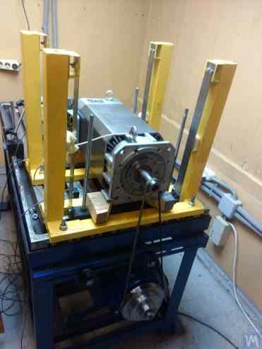
चित्र 3.7. विद्युत मोटर रोटरों को संतुलित करने की मशीन, असेंबल्ड, ए. मोखोव द्वारा विकसित।
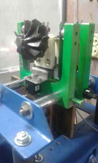
चित्र 3.8. टर्बोपंप रोटरों के संतुलन के लिए मशीन, जी. ग्लाज़ोव (बिश्केक) द्वारा विकसित
3.1.4.2. स्ट्रिप स्प्रिंग्स पर निलंबन के साथ सॉफ्ट बेयरिंग मशीन सपोर्ट्स
सस्पेंशन को सहारा देने के लिए उपयोग किए जाने वाले स्ट्रिप स्प्रिंग्स को डिजाइन करते समय स्प्रिंग स्ट्रिप की मोटाई और चौड़ाई के चयन पर ध्यान देना चाहिए, जो एक ओर सपोर्ट पर रोटर के स्थैतिक और गतिज भार को सहन करे, और दूसरी ओर सपोर्ट सस्पेंशन के टॉर्शनल कंपन की संभावना को रोकें, जो अक्षीय रन-आउट के रूप में प्रकट होती है।
स्ट्रिप स्प्रिंग सस्पेंशन का उपयोग करके बैलेंसिंग मशीनों के संरचनात्मक कार्यान्वयन के उदाहरण चित्र 2.1 - 2.5 (अनुभाग 2.1 देखें) के साथ-साथ इस अनुभाग के चित्र 3.7 और 3.8 में दिखाए गए हैं।
3.1.4.4. मशीनों के लिए कठोर भार वहन समर्थन
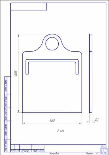
ग्राहकों के साथ हमारे व्यापक अनुभव से पता चलता है कि हाल ही में स्व-निर्मित बैलेंसर निर्माताओं का एक महत्वपूर्ण हिस्सा कठोर सपोर्ट वाली हार्ड बेयरिंग मशीनों को प्राथमिकता देने लगा है। खंड 2.2 में, चित्र 2.16 – 2.18 में ऐसे सपोर्ट का उपयोग करने वाली मशीनों के विभिन्न संरचनात्मक डिज़ाइनों के चित्र दर्शाए गए हैं। हमारे एक ग्राहक द्वारा अपनी मशीन के निर्माण के लिए विकसित किए गए कठोर सपोर्ट का एक विशिष्ट रेखाचित्र चित्र 3.10 में प्रस्तुत किया गया है। यह सपोर्ट एक सपाट स्टील प्लेट से बना है जिसमें P-आकार का खांचा है, जो पारंपरिक रूप से सपोर्ट को "कठोर" और "लचीले" भागों में विभाजित करता है। असंतुलन बल के प्रभाव में, सपोर्ट का "लचीला" भाग अपने "कठोर" भाग के सापेक्ष विकृत हो सकता है। इस विरूपण का परिमाण, जो सपोर्ट की मोटाई, खांचों की गहराई और सपोर्ट के "लचीले" और "कठोर" भागों को जोड़ने वाले पुल की चौड़ाई द्वारा निर्धारित होता है, मशीन के मापन प्रणाली के उपयुक्त सेंसरों का उपयोग करके मापा जा सकता है। पी-आकार के खांचे की गहराई एच, पुल की चौड़ाई टी, साथ ही समर्थन की मोटाई आर (चित्र 3.10 देखें) को ध्यान में रखते हुए, ऐसे समर्थनों की अनुप्रस्थ कठोरता की गणना करने की विधि के अभाव के कारण, इन डिजाइन मापदंडों को आमतौर पर डेवलपर्स द्वारा प्रयोगात्मक रूप से निर्धारित किया जाता है।
300-500 किलोग्राम से अधिक न होने वाले संतुलित रोटर द्रव्यमान वाली मशीनों के लिए, सपोर्ट की मोटाई 30-40 मिमी तक बढ़ाई जा सकती है, और 1000 से 3000 किलोग्राम तक के अधिकतम द्रव्यमान वाले रोटरों को संतुलित करने के लिए डिज़ाइन की गई मशीनों के लिए, सपोर्ट की मोटाई 50-60 मिमी या उससे अधिक हो सकती है। जैसा कि ऊपर वर्णित सपोर्टों के गतिशील गुणों के विश्लेषण से पता चलता है, अनुप्रस्थ तल (लचीले और कठोर भागों के सापेक्ष विरूपण के मापन का तल) में मापी गई उनकी प्राकृतिक कंपन आवृत्तियाँ आमतौर पर 100 हर्ट्ज़ या उससे अधिक होती हैं। संतुलित रोटर के घूर्णन अक्ष के साथ संरेखित दिशा में मापी गई हार्ड बेयरिंग सपोर्ट स्टैंड की प्राकृतिक कंपन आवृत्तियाँ आमतौर पर काफी कम होती हैं। मशीन पर संतुलित घूर्णनशील रोटरों के लिए परिचालन आवृत्ति सीमा की ऊपरी सीमा निर्धारित करते समय इन्हीं आवृत्तियों पर मुख्य रूप से विचार किया जाना चाहिए।
चित्र 3.26. ऑगर्स को संतुलित करने के लिए हार्ड बेयरिंग मशीन के निर्माण के लिए प्रयुक्त लेथ बेड का उपयोग करने का उदाहरण।
चित्र 3.27. शाफ्ट को संतुलित करने के लिए सॉफ्ट बेयरिंग मशीन के निर्माण के लिए प्रयुक्त लेथ बेड का उपयोग करने का उदाहरण।
चित्र 3.28. चैनलों से एक असेंबल बिस्तर बनाने का उदाहरण
चित्र 3.29. चैनलों से वेल्डेड बेड बनाने का उदाहरण
चित्र 3.30. चैनलों से वेल्डेड बेड के निर्माण का उदाहरण
चित्र 3.31. पॉलिमर कंक्रीट से बने बैलेंसिंग मशीन बेड का उदाहरण
आम तौर पर, ऐसे बिस्तरों के निर्माण में, उनके ऊपरी हिस्से को स्टील इंसर्ट से मजबूत किया जाता है, जिनका उपयोग गाइड के रूप में किया जाता है, जिन पर संतुलन मशीन के सपोर्ट स्टैंड आधारित होते हैं। हाल ही में, कंपन-रोधी कोटिंग वाले पॉलीमर कंक्रीट से बने बिस्तर व्यापक रूप से उपयोग में आ गए हैं। बिस्तरों के निर्माण की यह तकनीक ऑनलाइन अच्छी तरह से वर्णित है और इसे DIY निर्माता आसानी से लागू कर सकते हैं। उत्पादन की अपेक्षाकृत सरलता और कम लागत के कारण, इन बिस्तरों के धातु के समकक्षों की तुलना में कई प्रमुख लाभ हैं:
- कंपन दोलनों के लिए उच्च अवमंदन गुणांक;
- कम तापीय चालकता, बिस्तर के न्यूनतम तापीय विरूपण को सुनिश्चित करती है;
- उच्च संक्षारण प्रतिरोध;
- आंतरिक तनाव का अभाव।
3.1.4.3. बेलनाकार स्प्रिंग्स का उपयोग करके बनाए गए सॉफ्ट बेयरिंग मशीन सपोर्ट्स
चित्र 3.9 में सॉफ्ट बेयरिंग संतुलन मशीन का एक उदाहरण दिखाया गया है, जिसमें समर्थन संरचनाओं के डिज़ाइन में बेलनाकार संपीड़न स्प्रिंग्स का उपयोग किया गया है। इस डिज़ाइन समाधान की मुख्य कमी सामने और पीछे के समर्थन में स्प्रिंग विकृति की बदलती मात्राओं से संबंधित है, जो असममित रोटरों के संतुलन के दौरान समर्थन पर असमान भार होने पर होती है। यह स्वाभाविक रूप से समर्थनों के संरेखण में गड़बड़ी और ऊर्ध्वाधर समतल में रोटर अक्ष के तिरछेपन का कारण बनता है। इस दोष का एक नकारात्मक परिणाम उन बलों का उत्पन्न होना हो सकता है जो घूर्णन के दौरान रोटर को अक्षीय रूप से खिसका देते हैं।
चित्र 3.9. बेलनाकार स्प्रिंग्स का उपयोग करके संतुलन मशीनों के लिए सॉफ्ट बेयरिंग सपोर्ट निर्माण का वैरिएंट।
3.1.4.4. मशीनों के लिए कठोर भार वहन समर्थन
चित्र 3.10. संतुलन यंत्र के लिए हार्ड बेयरिंग समर्थन का रेखाचित्र
चित्र 3.11 और 3.12 में ऐसे सपोर्ट के विभिन्न उपयोगों को दर्शाया गया है, जिन्हें हमारे ग्राहकों की मशीनों के लिए बनाया गया है। मशीन निर्माताओं सहित हमारे कई ग्राहकों से प्राप्त आंकड़ों के आधार पर, विभिन्न आकारों और भार क्षमता वाली मशीनों के लिए सपोर्ट की मोटाई की आवश्यकताओं को निर्धारित किया जा सकता है। उदाहरण के लिए, 0.1 से 50-100 किलोग्राम वजन वाले रोटरों को संतुलित करने वाली मशीनों के लिए, सपोर्ट की मोटाई 20 मिमी हो सकती है।
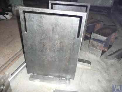
चित्र 3.11. संतुलन मशीन के लिए हार्ड बेयरिंग सपोर्ट, ए. सिनित्सिन द्वारा निर्मित
चित्र 3.12. संतुलन मशीन के लिए कठोर बेयरिंग समर्थन, डी. क्रासिलनिकोव द्वारा निर्मित
300-500 किलोग्राम से अधिक न होने वाले संतुलित रोटर द्रव्यमान वाली मशीनों के लिए, सपोर्ट की मोटाई 30-40 मिमी तक बढ़ाई जा सकती है, और 1000 से 3000 किलोग्राम तक के अधिकतम द्रव्यमान वाले रोटरों को संतुलित करने के लिए डिज़ाइन की गई मशीनों के लिए, सपोर्ट की मोटाई 50-60 मिमी या उससे अधिक हो सकती है। जैसा कि ऊपर वर्णित सपोर्टों के गतिशील गुणों के विश्लेषण से पता चलता है, अनुप्रस्थ तल (लचीले और कठोर भागों के सापेक्ष विरूपण के मापन का तल) में मापी गई उनकी प्राकृतिक कंपन आवृत्तियाँ आमतौर पर 100 हर्ट्ज़ या उससे अधिक होती हैं। संतुलित रोटर के घूर्णन अक्ष के साथ संरेखित दिशा में मापी गई हार्ड बेयरिंग सपोर्ट स्टैंड की प्राकृतिक कंपन आवृत्तियाँ आमतौर पर काफी कम होती हैं। मशीन पर संतुलित घूर्णनशील रोटरों के लिए परिचालन आवृत्ति सीमा की ऊपरी सीमा निर्धारित करते समय इन्हीं आवृत्तियों पर मुख्य रूप से विचार किया जाना चाहिए। जैसा कि ऊपर बताया गया है, इन आवृत्तियों का निर्धारण खंड 3.1 में वर्णित प्रभाव उत्तेजना विधि द्वारा किया जा सकता है।
3.2. संतुलन मशीनों की असेंबली का समर्थन
3.2.1. सहायक असेंबली के मुख्य प्रकार
हार्ड बेयरिंग और सॉफ्ट बेयरिंग दोनों की निर्माण प्रक्रिया में, सपोर्ट्स पर संतुलित रोटरों की स्थापना और घूर्णन के लिए निम्नलिखित प्रसिद्ध प्रकार की सहायक असेंबलियों की सिफारिश की जा सकती है, जिनमें शामिल हैं:
- प्रिज्मेटिक सहायक असेंबलियाँ;
- घूमने वाले रोलर्स के साथ असेंबली का समर्थन;
- स्पिंडल समर्थन असेंबली।
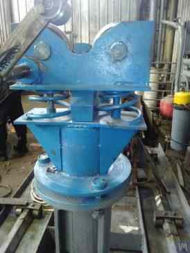
3.2.1.1. प्रिज़मैटिक सपोर्टिंग असेंबलीज़
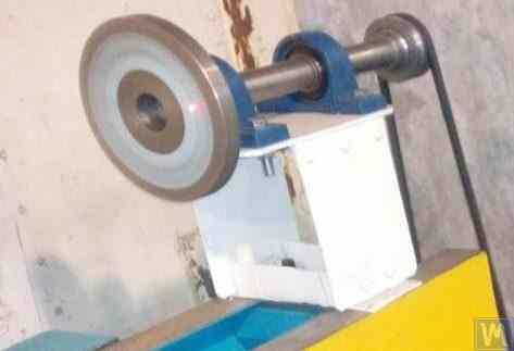
विभिन्न डिज़ाइन विकल्पों वाली ये असेंबली आमतौर पर छोटी और मध्यम आकार की मशीनों के सपोर्ट पर लगाई जाती हैं, जिन पर 50-100 किलोग्राम से अधिक द्रव्यमान वाले रोटरों को संतुलित किया जा सकता है। एक प्रिज्मीय सपोर्ट असेंबली के सबसे सरल संस्करण का उदाहरण चित्र 3.13 में दिखाया गया है। यह सपोर्ट असेंबली स्टील से बनी है और इसका उपयोग टरबाइन बैलेंसिंग मशीन पर किया जाता है। छोटी और मध्यम आकार की बैलेंसिंग मशीनों के कई निर्माता प्रिज्मीय सपोर्ट असेंबली बनाते समय टेक्सटोलाइट, फ्लोरोप्लास्टिक, कैप्रोलॉन आदि जैसी गैर-धात्विक सामग्री (डाइइलेक्ट्रिक्स) का उपयोग करना पसंद करते हैं।
3.13. प्रिज़मैटिक सपोर्टिंग असेंबली का निष्पादन प्रकार, जो ऑटोमोबाइल टर्बाइनों के लिए बैलेंसिंग मशीन पर उपयोग किया जाता है।
उदाहरण के लिए, जी. ग्लाज़ोव ने अपनी मशीन में इसी प्रकार के सहायक असेंबली (ऊपर चित्र 3.8 देखें) का उपयोग किया है, जो ऑटोमोबाइल टर्बाइनों को संतुलित करने के लिए भी बनाई गई है। फ्लोरोप्लास्टिक से बने प्रिज्मीय सहायक असेंबली (चित्र 3.14 देखें) का मूल तकनीकी समाधान एलएलसी "टेक्नोबैलेंस" द्वारा प्रस्तावित किया गया है।
चित्र 3.14. एलएलसी "टेक्नोबैलेंस" द्वारा निर्मित प्रिज्मीय सपोर्ट असेंबली"
यह विशेष सहायक असेंबली दो बेलनाकार स्लीव 1 और 2 से बनी है, जो एक दूसरे से एक कोण पर स्थापित हैं और सहायक अक्षों पर स्थिर हैं। संतुलित रोटर सिलेंडरों की जनरेटिंग लाइनों के साथ स्लीव की सतहों के संपर्क में आता है, जिससे रोटर शाफ्ट और सपोर्ट के बीच संपर्क क्षेत्र कम हो जाता है, और परिणामस्वरूप सपोर्ट में घर्षण बल कम हो जाता है। यदि आवश्यक हो, तो रोटर शाफ्ट के संपर्क क्षेत्र में सपोर्ट की सतह पर घिसावट या क्षति होने की स्थिति में, स्लीव को उसके अक्ष के चारों ओर एक निश्चित कोण पर घुमाकर घिसावट की भरपाई की जा सकती है। यह ध्यान रखना महत्वपूर्ण है कि जब अधात्विक पदार्थों से बनी सहायक असेंबली का उपयोग किया जाता है, तो संतुलित रोटर को मशीन बॉडी से ग्राउंड करने की संरचनात्मक व्यवस्था करना आवश्यक है, जिससे संचालन के दौरान उत्पन्न होने वाले शक्तिशाली स्थैतिक विद्युत आवेशों का खतरा समाप्त हो जाता है। इससे, पहला, मशीन के मापन प्रणाली के प्रदर्शन को प्रभावित करने वाले विद्युत हस्तक्षेप और व्यवधानों को कम करने में मदद मिलती है, और दूसरा, कर्मियों के स्थैतिक विद्युत के प्रभाव से प्रभावित होने का खतरा समाप्त हो जाता है।
3.2.1.2. रोलर समर्थन असेंबली
ये असेंबली आम तौर पर 50 किलोग्राम या उससे अधिक द्रव्यमान वाले रोटरों को संतुलित करने के लिए डिज़ाइन की गई मशीनों के सपोर्ट पर लगाई जाती हैं। इनका उपयोग प्रिज्मीय सपोर्ट की तुलना में सपोर्ट में घर्षण बलों को काफी कम कर देता है, जिससे संतुलित रोटर का घूर्णन सुगम हो जाता है। उदाहरण के लिए, चित्र 3.15 में एक सपोर्ट असेंबली का डिज़ाइन दिखाया गया है जिसमें उत्पाद की स्थिति निर्धारण के लिए रोलर्स का उपयोग किया जाता है। इस डिज़ाइन में, मानक रोलिंग बियरिंग का उपयोग रोलर 1 और 2 के रूप में किया जाता है, जिनके बाहरी वलय मशीन के सपोर्ट 3 में स्थिर अक्षों पर घूमते हैं। चित्र 3.16 में एक रोलर सपोर्ट असेंबली के अधिक जटिल डिज़ाइन का रेखाचित्र दर्शाया गया है, जिसे संतुलन मशीनों के एक स्व-निर्मित निर्माता ने अपनी परियोजना में लागू किया है। चित्र से स्पष्ट है कि रोलर (और परिणामस्वरूप संपूर्ण सहायक असेंबली) की भार वहन क्षमता बढ़ाने के लिए, रोलर बॉडी 3 में रोलिंग बियरिंग 1 और 2 की एक जोड़ी स्थापित की गई है। इस डिज़ाइन का व्यावहारिक कार्यान्वयन, इसके सभी स्पष्ट लाभों के बावजूद, एक जटिल कार्य प्रतीत होता है, क्योंकि इसके लिए रोलर बॉडी 3 का स्वतंत्र निर्माण आवश्यक है, जिस पर ज्यामितीय सटीकता और सामग्री के यांत्रिक गुणों के लिए बहुत उच्च आवश्यकताएं लागू होती हैं।
चित्र 3.15. रोलर सपोर्टिंग असेंबली डिज़ाइन का उदाहरण
चित्र 3.16. दो रोलिंग बेयरिंग्स के साथ रोलर सपोर्टिंग असेंबली डिज़ाइन का उदाहरण
चित्र 3.17 में LLC "टेक्नोबैलेंस" के विशेषज्ञों द्वारा विकसित स्व-संरेखण रोलर सपोर्टिंग असेंबली का एक डिज़ाइन वेरिएंट दिखाया गया है। इस डिज़ाइन में, रोलर्स को दो अतिरिक्त डिग्री ऑफ़ फ़्रीडम प्रदान करके उनकी स्व-संरेखण क्षमता प्राप्त की जाती है, जिससे रोलर्स X और Y अक्षों के चारों ओर छोटे कोणीय गति कर सकते हैं। इस प्रकार की सपोर्टिंग असेंबली, जो संतुलित रोटर्स की स्थापना में उच्च परिशुद्धता सुनिश्चित करती हैं, आमतौर पर भारी बैलेंसिंग मशीनों के सपोर्ट पर उपयोग के लिए अनुशंसित की जाती हैं।
चित्र 3.17. स्व-संरेखित रोलर समर्थन असेंबली डिजाइन का उदाहरण
जैसा कि पहले उल्लेख किया गया था, रोलर सपोर्ट असेंबलीज़ में आमतौर पर सटीक निर्माण और कठोरता के लिए काफी उच्च आवश्यकताएँ होती हैं। विशेष रूप से, रोलर्स के रेडियल रनआउट के लिए निर्धारित सहनशीलता 3–5 माइक्रोन से अधिक नहीं होनी चाहिए।
व्यवहार में, यह उपलब्धि हमेशा प्रसिद्ध निर्माताओं द्वारा भी हासिल नहीं की जा सकती। उदाहरण के लिए, लेखक द्वारा संतुलन मशीन मॉडल H8V, ब्रांड "के. शेनक" के लिए स्पेयर पार्ट्स के रूप में खरीदे गए नए रोलर सपोर्ट असेंबली के एक सेट के रेडियल रनआउट के परीक्षण के दौरान, उनके रोलर्स का रेडियल रनआउट 10-11 माइक्रोन तक पहुंच गया।
3.2.1.3. स्पिंडल समर्थन असेंबली
जब संतुलन मशीनों पर फ्लैंग माउंटिंग वाले रोटर (उदाहरण के लिए, कार्डन शाफ्ट) का संतुलन किया जाता है, तब संतुलित उत्पादों की स्थिति निर्धारण, माउंटिंग और घूर्णन के लिए स्पिंडल सहायक असेंबली के रूप में उपयोग किए जाते हैं।
स्पिंडल संतुलन मशीनों के सबसे जटिल और महत्वपूर्ण घटकों में से एक हैं, जो आवश्यक संतुलन गुणवत्ता प्राप्त करने के लिए मुख्य रूप से जिम्मेदार हैं।
स्पिंडल के डिजाइन और निर्माण का सिद्धांत और व्यवहार काफी अच्छी तरह से विकसित है और प्रकाशनों की एक विस्तृत श्रृंखला में परिलक्षित होता है, जिनमें से, डॉ. इंजी. डी.एन. रेशेतोव द्वारा संपादित मोनोग्राफ "धातु-काटने वाली मशीन टूल्स के विवरण और तंत्र" [1] डेवलपर्स के लिए सबसे उपयोगी और सुलभ के रूप में सामने आता है।
संतुलन मशीन स्पिंडलों के डिजाइन और निर्माण में विचार किए जाने वाले मुख्य आवश्यकताओं में से, निम्नलिखित को प्राथमिकता दी जानी चाहिए:
a) स्पिंडल असेंबली संरचना की उच्च कठोरता प्रदान करना, जो संतुलित रोटर के असंतुलन बलों के प्रभाव में होने वाली अस्वीकार्य विकृतियों को रोकने के लिए पर्याप्त हो;
b) स्पिंडल के घूर्णन अक्ष की स्थिति की स्थिरता सुनिश्चित करना, जो स्पिंडल के रेडियल, एक्सियल, और एक्सियल रनआउट के अनुमेय मानों द्वारा विशेषता है;
c) स्पिंडल जर्नलों के उचित घिसाव प्रतिरोध को सुनिश्चित करना, साथ ही संतुलित उत्पादों को माउंट करने के लिए उपयोग की जाने वाली इसकी सीटिंग और सहायक सतहों का भी।
इन आवश्यकताओं के व्यावहारिक कार्यान्वयन का विवरण कार्य [1] के खंड VI "स्पिंडल और उनके समर्थन" में दिया गया है।
विशेष रूप से, स्पिंडलों की कठोरता और घूर्णी सटीकता सत्यापित करने के लिए पद्धतियाँ, बेयरिंग चुनने की सिफारिशें, स्पिंडल सामग्री के चयन और उसकी कठोरता बढ़ाने के तरीके, साथ ही इस विषय पर अन्य कई उपयोगी जानकारियाँ उपलब्ध हैं।
कार्य [1] में उल्लेख है कि अधिकांश प्रकार की धातु-काटने वाली मशीन टूल्स के स्पिंडलों के डिज़ाइन में मुख्यतः दो-बेयरिंग योजना का उपयोग किया जाता है।
मिलिंग मशीन स्पिंडलों में प्रयुक्त इस प्रकार की दो-बेयरिंग योजना के डिज़ाइन वेरिएंट का एक उदाहरण (विवरण कार्य [1] में मिल सकते हैं) चित्र 3.18 में दिखाया गया है।
यह योजना संतुलन मशीन स्पिंडलों के निर्माण के लिए काफी उपयुक्त है, जिनके डिज़ाइन वेरिएंट के उदाहरण नीचे आकृतियों 3.19–3.22 में दिखाए गए हैं।
चित्र 3.18. दो-बेयरिंग मिलिंग मशीन स्पिंडल का स्केच
चित्र 3.19 संतुलन मशीन की अग्रणी स्पिंडल असेंबली के एक डिज़ाइन वेरिएंट को दर्शाता है, जो दो रेडियल-थ्रस्ट बेयरिंग्स पर घूमती है, जिनमें से प्रत्येक का अपना स्वतंत्र आवास 1 और 2 है। एक फ्लैंज 4, जो कार्डन शाफ्ट के फ्लैंज माउंटिंग के लिए है, और एक पुली 5, जो V-बेल्ट ड्राइव के माध्यम से इलेक्ट्रिक मोटर से स्पिंडल तक घूर्णन संचारित करने के लिए उपयोग की जाती है, स्पिंडल शाफ्ट 3 पर लगे हुए हैं।
आकृति 3.19. दो स्वतंत्र बेयरिंग समर्थनों पर स्पिंडल डिज़ाइन का उदाहरण
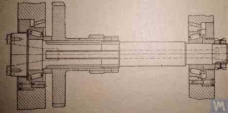
आकृति 3.20 और 3.21 दो निकट-संबंधित अग्रणी स्पिंडल असेंबली डिज़ाइन दर्शाते हैं। दोनों मामलों में, स्पिंडल बेयरिंग्स एक सामान्य हाउसिंग 1 में स्थापित की जाती हैं, जिसमें स्पिंडल शाफ्ट स्थापित करने के लिए एक थ्रू एक्सियल छेद होता है। इस छेद के प्रवेश और निकास पर, हाउसिंग में विशेष बोर होते हैं (चित्रों में नहीं दिखाए गए), जो रेडियल थ्रस्ट बेयरिंग्स (रोलर या बॉल) को समायोजित करने के लिए डिज़ाइन किए गए हैं, और विशेष फ्लैंज कवर 5 होते हैं, जिनका उपयोग बेयरिंग्स की बाहरी रिंगों को सुरक्षित करने के लिए किया जाता है।
आकृति 3.20. एक सामान्य आवास में स्थापित दो बेयरिंग समर्थनों पर अग्रणी स्पिंडल डिज़ाइन का उदाहरण 1
आकृति 3.21. एक सामान्य आवास में स्थापित दो बेयरिंग समर्थनों पर अग्रणी स्पिंडल डिज़ाइन का उदाहरण 2
जैसा कि पिछले संस्करण में (देखें आकृति 3.19), स्पिंडल शाफ्ट पर एक फेसप्लेट 2 स्थापित किया गया है, जिसका उद्देश्य ड्राइव शाफ्ट के फ्लैंग माउंटिंग के लिए है, और एक पुली 3, जिसका उपयोग बेल्ट ड्राइव के माध्यम से इलेक्ट्रिक मोटर से स्पिंडल तक घूर्णन संचारित करने के लिए किया जाता है। एक लिम्ब 4 भी स्पिंडल शाफ्ट से जुड़ा होता है, जिसका उपयोग स्पिंडल की कोणीय स्थिति निर्धारित करने के लिए किया जाता है, जो संतुलन के दौरान रोटर पर परीक्षण और सुधारात्मक भार स्थापित करते समय उपयोगी होता है।
आकृति 3.22. एक ड्राइवन (पछला) स्पिंडल के डिज़ाइन का उदाहरण
आकृति 3.22 मशीन की चालित (रियर) स्पिंडल असेंबली का एक डिज़ाइन वेरिएंट दिखाया गया है, जो अग्रणी स्पिंडल से केवल ड्राइव पुली और लिंब की अनुपस्थिति के कारण भिन्न है, क्योंकि उनकी आवश्यकता नहीं होती है।
चित्र 3.23. संचालित (पिछली) धुरी के डिजाइन निष्पादन का उदाहरण
जैसा कि में देखा गया आंकड़े 3.20 – 3.22उपरोक्त स्पिंडल असेंबलीज़ को विशेष क्लैम्प (स्ट्रैप्स) 6 का उपयोग करके संतुलन मशीनों के सॉफ्ट बेयरिंग सपोर्ट्स से संलग्न किया जाता है। यदि आवश्यक हो तो अन्य संलग्न करने के तरीके भी अपनाए जा सकते हैं, जिससे स्पिंडल असेंबली को सपोर्ट पर उचित कठोरता और सटीकता के साथ स्थापित किया जा सके।
आकृति 3.23 एक स्पिंडल के समान फ्लैंग माउंटिंग के एक डिज़ाइन को दर्शाता है, जिसका उपयोग संतुलन मशीन के हार्ड बेयरिंग सपोर्ट पर इसकी स्थापना के लिए किया जा सकता है।
3.2.1.3.4. स्पिंडल कठोरता और रेडियल रनआउट की गणना
स्पिंडल की कठोरता और अपेक्षित रेडियल रनआउट निर्धारित करने के लिए, सूत्र 3.4 का उपयोग किया जा सकता है (चित्र 3.24 में गणना योजना देखें):
कहाँ:
- Y स्पिंडल कंसोल के अंत में स्पिंडल का प्रत्यास्थ विस्थापन, सेंटीमीटर में;
- P - स्पिंडल कंसोल पर लगने वाला परिकलित भार, किलोग्राम में;
- ए - स्पिंडल का पिछला बेयरिंग सपोर्ट;
- बी - स्पिंडल का फ्रंट बेयरिंग सपोर्ट;
- जी स्पिंडल कंसोल की लंबाई, सेंटीमीटर में;
- सी - स्पिंडल के सपोर्ट A और B के बीच की दूरी, सेंटीमीटर में;
- जे1 - सपोर्ट के बीच स्पिंडल सेक्शन का औसत जड़त्व आघूर्ण, सेमी⁴;
- जे2 - स्पिंडल कंसोल अनुभाग का औसत जड़त्व आघूर्ण, सेमी⁴;
- जेबी और जेए स्पिंडल के आगे और पीछे के सपोर्ट के लिए बियरिंग की कठोरता, क्रमशः, किलोग्राम/सेमी में।
सूत्र 3.4 को रूपांतरित करके, स्पिंडल असेंबली कठोरता का वांछित गणना मूल्य jшп निर्धारित किया जा सकता है:
मध्यम आकार की संतुलन मशीनों के लिए कार्य [1] की सिफारिशों को ध्यान में रखते हुए, यह मान 50 किग्रा/µm से कम नहीं होना चाहिए।
रेडियल रनआउट की गणना के लिए, सूत्र 3.5 का उपयोग किया जाता है:
कहाँ:
- Δ स्पिंडल कंसोल छोर पर रेडियल रनआउट है, µm;
- ∆B फ्रंट स्पिंडल बेयरिंग का रेडियल रनआउट है, µm;
- ∆A रियर स्पिंडल बेयरिंग का रेडियल रनआउट है, µm;
- g स्पिंडल कंसोल की लंबाई, सेमी है;
- c धुरी के आधार A और B के बीच की दूरी, सेमी है।
3.2.1.3.5. स्पिंडल संतुलन आवश्यकताओं को सुनिश्चित करना
संतुलन मशीनों के स्पिंडल असेंबली का अच्छी तरह से संतुलित होना आवश्यक है, क्योंकि कोई भी वास्तविक असंतुलन संतुलित किए जा रहे रोटर में अतिरिक्त त्रुटि के रूप में स्थानांतरित हो जाएगा। स्पिंडल के अवशिष्ट असंतुलन के लिए तकनीकी सहनशीलता निर्धारित करते समय, आमतौर पर यह सलाह दी जाती है कि इसके संतुलन का परिशुद्धता वर्ग मशीन पर संतुलित किए जा रहे उत्पाद के परिशुद्धता वर्ग से कम से कम 1-2 वर्ग उच्च होना चाहिए।
ऊपर चर्चित स्पिंडलों की डिजाइन विशेषताओं को ध्यान में रखते हुए, उनका संतुलन दो तलों में किया जाना चाहिए।
3.2.1.3.6. स्पिंडल बियरिंग्स के लिए बियरिंग लोड क्षमता और स्थायित्व आवश्यकताओं को सुनिश्चित करना
Spindles को design करते समय और bearing sizes का चयन करते समय, bearings की durability और load capacity का प्रारंभिक आकलन करना उचित है। इन calculations की methodology ISO 281 "Rolling Bearings - Dynamic Load Ratings and Rating Life" [3] में, साथ ही अनेक rolling bearing handbooks (digital सहित) में विस्तार से दी जा सकती है।
3.2.1.3.7. स्पिंडल बियरिंग्स की स्वीकार्य हीटिंग के लिए आवश्यकताओं को सुनिश्चित करना
कार्य [1] की सिफारिशों के अनुसार, स्पिंडल बीयरिंग के बाहरी रिंगों का अधिकतम स्वीकार्य ताप 70 डिग्री सेल्सियस से अधिक नहीं होना चाहिए। हालांकि, उच्च गुणवत्ता वाले संतुलन को सुनिश्चित करने के लिए, बाहरी रिंगों का अनुशंसित ताप 40 - 45 डिग्री सेल्सियस से अधिक नहीं होना चाहिए।
3.2.1.3.8. बेल्ट ड्राइव का प्रकार और स्पिंडल के लिए ड्राइव पुली का डिज़ाइन चुनना
बैलेंसिंग मशीन के ड्राइविंग स्पिंडल को डिज़ाइन करते समय, फ्लैट बेल्ट ड्राइव का उपयोग करके इसके रोटेशन को सुनिश्चित करने की अनुशंसा की जाती है। स्पिंडल संचालन के लिए इस तरह के ड्राइव के उचित उपयोग का एक उदाहरण प्रस्तुत किया गया है आंकड़े 3.20 और 3.23. v-belt या toothed belt drives का उपयोग अवांछनीय है, क्योंकि वे belts और pulleys की geometric inaccuracies के कारण spindle पर अतिरिक्त dynamic loads लागू कर सकते हैं, जो balancing के दौरान additional measurement errors का कारण बन सकते हैं। Flat drive belts के pulleys के लिए recommended requirements national standard GOST 17383-73 "Pulleys for flat drive belts" [4] में दी गई हैं।
ड्राइव पुली को स्पिंडल के पिछले सिरे पर, बेयरिंग असेंबली के जितना संभव हो सके उतना करीब (न्यूनतम संभव ओवरहैंग के साथ) रखा जाना चाहिए। स्पिंडल के निर्माण में पुली के ओवरहैंगिंग प्लेसमेंट के लिए डिज़ाइन निर्णय, जो चित्र में दिखाया गया है चित्र 3.19, असफल माना जा सकता है, क्योंकि यह स्पिंडल समर्थन पर अभिनय करने वाले गतिशील ड्राइव लोड के क्षण को काफी हद तक बढ़ा देता है।
इस डिजाइन का एक अन्य महत्वपूर्ण दोष वी-बेल्ट ड्राइव का उपयोग है, जिसके निर्माण और संयोजन में अशुद्धियां भी स्पिंडल पर अवांछनीय अतिरिक्त भार का स्रोत हो सकती हैं।
3.3. बिस्तर (फ्रेम)
बेड बैलेंसिंग मशीन की मुख्य सहायक संरचना है, जिस पर इसके मुख्य तत्व आधारित होते हैं, जिसमें सपोर्ट पोस्ट और ड्राइव मोटर शामिल हैं। बैलेंसिंग मशीन के बेड का चयन या निर्माण करते समय, यह सुनिश्चित करना आवश्यक है कि यह कई आवश्यकताओं को पूरा करता है, जिसमें आवश्यक कठोरता, ज्यामितीय परिशुद्धता, कंपन प्रतिरोध और इसके गाइड का पहनने का प्रतिरोध शामिल है।
अभ्यास से पता चलता है कि अपनी जरूरतों के लिए मशीनों का निर्माण करते समय, निम्नलिखित बिस्तर विकल्पों का सबसे अधिक उपयोग किया जाता है:
- प्रयुक्त धातु-काटने वाली मशीनों (खराद, काष्ठकला, आदि) से बने कच्चे लोहे के बेड;
- चैनलों पर आधारित इकट्ठे बेड, बोल्ट कनेक्शन का उपयोग करके इकट्ठे किए गए;
- चैनलों पर आधारित वेल्डेड बेड;
- कंपन-अवशोषित कोटिंग्स के साथ पॉलिमर कंक्रीट बेड।
चित्र 3.25. कार्डन शाफ्ट को संतुलित करने के लिए मशीन के निर्माण हेतु प्रयुक्त वुडवर्किंग मशीन बेड का उपयोग करने का उदाहरण।
3.4. संतुलन मशीनों के लिए ड्राइव
जैसा कि संतुलन मशीनों के निर्माण में हमारे ग्राहकों द्वारा उपयोग किए जाने वाले डिज़ाइन समाधानों के विश्लेषण से पता चलता है, वे मुख्य रूप से ड्राइव के डिज़ाइन के दौरान परिवर्तनीय आवृत्ति ड्राइव से सुसज्जित एसी मोटर्स का उपयोग करने पर ध्यान केंद्रित करते हैं। यह दृष्टिकोण न्यूनतम लागत के साथ संतुलित रोटर्स के लिए समायोज्य रोटेशन गति की एक विस्तृत श्रृंखला की अनुमति देता है। संतुलित रोटर्स को घुमाने के लिए उपयोग की जाने वाली मुख्य ड्राइव मोटर्स की शक्ति आमतौर पर इन रोटर्स के द्रव्यमान के आधार पर चुनी जाती है और लगभग हो सकती है:
- 5 किलोग्राम या उससे कम द्रव्यमान वाले रोटरों को संतुलित करने के लिए डिज़ाइन की गई मशीनों के लिए 0.25 - 0.72 किलोवाट;
- 5 किलोग्राम से अधिक या उसके बराबर द्रव्यमान वाले रोटरों को संतुलित करने के लिए डिज़ाइन की गई मशीनों के लिए 0.72 - 1.2 किलोवाट;
- 50 किलोग्राम से अधिक और 100 किलोग्राम से कम द्रव्यमान वाले रोटरों को संतुलित करने के लिए डिज़ाइन की गई मशीनों के लिए 1.2 - 1.5 किलोवाट;
- 100 किलोग्राम से अधिक और 500 किलोग्राम से कम द्रव्यमान वाले रोटरों को संतुलित करने के लिए डिज़ाइन की गई मशीनों के लिए 1.5 - 2.2 किलोवाट;
- 2.2 - 5 किलोवाट उन मशीनों के लिए जो 500 ≤ 1000 किलोग्राम द्रव्यमान वाले रोटरों को संतुलित करने के लिए डिज़ाइन की गई हैं;
- 1000 से 3000 किलोग्राम द्रव्यमान वाले रोटरों को संतुलित करने के लिए डिज़ाइन की गई मशीनों के लिए 5 - 7.5 किलोवाट।
इन मोटरों को मशीन बेड या इसकी नींव पर मजबूती से लगाया जाना चाहिए। मशीन पर (या स्थापना स्थल पर) स्थापना से पहले, मुख्य ड्राइव मोटर, इसके आउटपुट शाफ्ट पर लगे पुली के साथ, सावधानीपूर्वक संतुलित किया जाना चाहिए। परिवर्तनीय आवृत्ति ड्राइव के कारण होने वाले विद्युत चुम्बकीय हस्तक्षेप को कम करने के लिए, इसके इनपुट और आउटपुट पर नेटवर्क फ़िल्टर स्थापित करने की अनुशंसा की जाती है। ये ड्राइव के निर्माताओं द्वारा आपूर्ति किए गए मानक ऑफ-द-शेल्फ उत्पाद या फेराइट रिंग का उपयोग करके बनाए गए होममेड फ़िल्टर हो सकते हैं।
4. संतुलन यंत्रों की मापन प्रणालियाँ
संतुलन मशीनों के अधिकांश शौकिया निर्माता, जो एलएलसी "किनेमेटिक्स" (वाइब्रोमेरा) से संपर्क करते हैं, अपने डिज़ाइनों में हमारी कंपनी द्वारा निर्मित "बैलेंसेट" श्रृंखला के मापन प्रणालियों का उपयोग करने की योजना बनाते हैं। हालांकि, कुछ ऐसे ग्राहक भी हैं जो ऐसी मापन प्रणालियों का निर्माण स्वयं करना चाहते हैं। इसलिए, संतुलन मशीन के लिए मापन प्रणाली के निर्माण पर विस्तार से चर्चा करना उचित होगा। इन प्रणालियों की मुख्य आवश्यकता संतुलित रोटर की घूर्णन आवृत्ति पर उत्पन्न होने वाले कंपन संकेत के घूर्णी घटक के आयाम और चरण का उच्च परिशुद्धता मापन प्रदान करना है। यह लक्ष्य आमतौर पर तकनीकी समाधानों के संयोजन द्वारा प्राप्त किया जाता है, जिनमें शामिल हैं:
- उच्च संकेत रूपांतरण गुणांक वाले कंपन सेंसरों का उपयोग;
- आधुनिक लेजर फेज एंगल सेंसरों का उपयोग;
- हार्डवेयर का निर्माण (या उपयोग) जो सेंसर संकेतों के प्रवर्धन और डिजिटल रूपांतरण (प्राथमिक संकेत प्रसंस्करण) की अनुमति देता है;
- कंपन संकेत के सॉफ्टवेयर प्रसंस्करण का कार्यान्वयन, जो संतुलित रोटर की घूर्णन आवृत्ति पर प्रकट होने वाले कंपन संकेत के घूर्णी घटक के उच्च-रिज़ॉल्यूशन और स्थिर निष्कर्षण की अनुमति देगा (द्वितीयक प्रसंस्करण)।
नीचे, हम ऐसे तकनीकी समाधानों के ज्ञात प्रकारों पर विचार करते हैं, जिन्हें कई प्रसिद्ध संतुलन उपकरणों में लागू किया गया है।
4.1. कंपन संवेदकों का चयन
संतुलन मशीनों की मापन प्रणालियों में विभिन्न प्रकार के कंपन सेंसर (ट्रांसड्यूसर) का उपयोग किया जा सकता है, जिनमें शामिल हैं:
- कंपन त्वरण संवेदक (एक्सेलेरोमीटर);
- कंपन वेग सेंसर;
- कंपन विस्थापन सेंसर;
- बल संवेदक।
4.1.1. कंपन त्वरण सेंसर
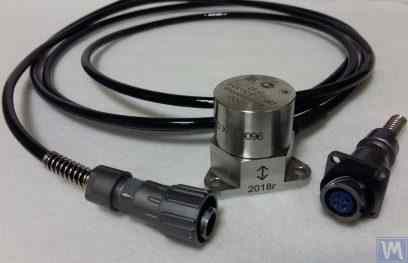
कंपन त्वरण सेंसरों में, पीज़ो और कैपेसिटिव (चिप) एक्सेलेरोमीटर सबसे व्यापक रूप से उपयोग किए जाते हैं, जिनका उपयोग सॉफ्ट बेयरिंग प्रकार की बैलेंसिंग मशीनों में प्रभावी ढंग से किया जा सकता है। व्यवहार में, आमतौर पर 10 से 30 mV/(m/s²) के रूपांतरण गुणांक (Kpr) वाले कंपन त्वरण सेंसरों का उपयोग करना स्वीकार्य है। विशेष रूप से उच्च संतुलन सटीकता की आवश्यकता वाली बैलेंसिंग मशीनों में, 100 mV/(m/s²) और उससे अधिक Kpr स्तर वाले एक्सेलेरोमीटरों का उपयोग करना उचित है। बैलेंसिंग मशीनों के लिए कंपन सेंसर के रूप में उपयोग किए जा सकने वाले पीज़ो एक्सेलेरोमीटरों के उदाहरण के रूप में, चित्र 4.1 में LLC "इज़मेरिटेल" द्वारा निर्मित DN3M1 और DN3M1V6 पीज़ो एक्सेलेरोमीटर दिखाए गए हैं।
चित्र 4.1. पाइज़ो एक्सेलेरोमीटर DN 3M1 और DN 3M1V6
ऐसे सेंसरों को कंपन मापन उपकरणों और प्रणालियों से जोड़ने के लिए, बाहरी या अंतर्निहित चार्ज एम्पलीफायरों का उपयोग करना आवश्यक है।
चित्र 4.2. कैपेसिटिव एक्सेलेरोमीटर AD1, LLC "किनेमेटिक्स" (वाइब्रोमेरा) द्वारा निर्मित।
यह ध्यान देने योग्य है कि इन सेंसरों में, जिनमें व्यापक रूप से उपयोग किए जाने वाले कैपेसिटिव एक्सेलेरोमीटर ADXL 345 (देखें आकृति 4.3) के मार्केट बोर्ड शामिल हैं, पिएज़ो एक्सेलेरोमीटरों की तुलना में कई महत्वपूर्ण लाभ हैं। विशेष रूप से, समान तकनीकी विशेषताओं के साथ ये 4 से 8 गुना सस्ते होते हैं। इसके अलावा, इन्हें पिएज़ो एक्सेलेरोमीटरों के लिए आवश्यक महंगे और नाजुक चार्ज एम्पलीफायरों के उपयोग की आवश्यकता नहीं होती।
जहाँ संतुलन मशीनों की मापन प्रणालियों में दोनों प्रकार के एक्सेलेरोमीटरों का उपयोग किया जाता है, वहाँ सेंसर संकेतों का हार्डवेयर एकीकरण (या द्वि-एकीकरण) आमतौर पर किया जाता है।
चित्र 4.2. कैपेसिटिव एक्सेलेरोमीटर AD 1, असेंबल्ड।
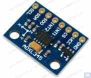
चित्र 4.3. कैपेसिटिव एक्सेलेरोमीटर बोर्ड ADXL 345।
इस मामले में, प्रारंभिक सेंसर संकेत, जो कम्पन त्वरण के समानुपाती होता है, तदनुसार कम्पन वेग या विस्थापन के समानुपाती संकेत में परिवर्तित हो जाता है। कम्पन संकेत के द्वि-एकीकरण की प्रक्रिया निम्न-गति संतुलन मशीनों के मापन प्रणालियों में एक्सेलेरोमीटर के उपयोग के लिए विशेष रूप से प्रासंगिक है, जहाँ संतुलन के दौरान निचले रोटर घूर्णन आवृत्ति सीमा 120 आरपीएम और उससे कम तक पहुँच सकती है। संतुलन मशीनों की माप प्रणालियों में कैपेसिटिव एक्सेलेरोमीटर का उपयोग करते समय, यह ध्यान में रखा जाना चाहिए कि एकीकरण के बाद, उनके संकेतों में 0.5 से 3 हर्ट्ज़ की आवृत्ति सीमा में निम्न-आवृत्ति हस्तक्षेप हो सकता है। यह इन सेंसरों का उपयोग करने के लिए अभिप्रेत मशीनों पर संतुलन की निचली आवृत्ति सीमा को सीमित कर सकता है।
4.1.2. कंपन वेग सेंसर
4.1.2.1. प्रेरक कम्पन वेग संवेदक।
इन सेंसरों में एक प्रेरक कुंडल और एक चुंबकीय कोर शामिल होते हैं। जब कुंडल एक स्थिर कोर के सापेक्ष कंपन करता है (या कोर एक स्थिर कुंडल के सापेक्ष), तो कुंडल में एक विद्युत-चुंबकीय बल (EMF) प्रेरित होता है, जिसका वोल्टेज सेंसर के चलने वाले तत्व की कंपन वेग के सीधे आनुपातिक होता है। इंडक्टिव सेंसरों के रूपांतरण गुणांक (Кпр) आमतौर पर काफी अधिक होते हैं, जो कई दर्जन या सैकड़ों mV/mm/sec तक पहुँच जाते हैं। विशेष रूप से, शेंक मॉडल T77 सेंसर का रूपांतरण गुणांक 80 mV/mm/sec है, और IRD मेकेनलिसिस मॉडल 544M सेंसर के लिए यह 40 mV/mm/sec है। कुछ मामलों में (उदाहरण के लिए, शेंक बैलेंसिंग मशीनों में), एक यांत्रिक एम्पलीफायर के साथ विशेष उच्च संवेदनशीलता वाले प्रेरक कंपन वेग सेंसर का उपयोग किया जाता है, जहाँ Кпр 1000 mV/mm/sec से अधिक हो सकता है। यदि बैलेंसिंग मशीनों की माप प्रणालियों में प्रेरक कंपन वेग सेंसर का उपयोग किया जाता है, तो कंपन वेग के अनुपाती विद्युत संकेत के हार्डवेयर एकीकरण को भी किया जा सकता है, और इसे कंपन विस्थापन के अनुपाती संकेत में परिवर्तित किया जा सकता है।
चित्र 4.4. IRD Mechanalysis द्वारा मॉडल 544M सेंसर।
चित्र 4.5. शेंक द्वारा मॉडल T77 सेंसर
यह ध्यान देने योग्य है कि उनके उत्पादन में श्रम-गहनता के कारण प्रेरक कंपन वेग सेंसर काफी दुर्लभ और महंगे होते हैं। इसलिए, इन सेंसरों के स्पष्ट लाभों के बावजूद, संतुलन मशीनों के शौकिया निर्माता इन्हें बहुत ही कम इस्तेमाल करते हैं।
4.2. फेज एंगल सेंसर
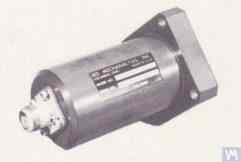
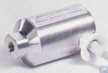
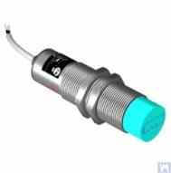
संतुलित रोटर के घूर्णन कोण के साथ कंपन मापन प्रक्रिया को सिंक्रनाइज़ करने के लिए, लेज़र (फोटोइलेक्ट्रिक) या प्रेरक सेंसर जैसे फेज़ एंगल सेंसर का उपयोग किया जाता है। ये सेंसर घरेलू और अंतर्राष्ट्रीय दोनों निर्माताओं द्वारा विभिन्न डिज़ाइनों में निर्मित किए जाते हैं। इन सेंसरों की कीमत लगभग 40 से 200 डॉलर तक काफी भिन्न हो सकती है। ऐसे ही एक उपकरण का उदाहरण "डायमेक्स" द्वारा निर्मित फेज़ एंगल सेंसर है, जिसे चित्र 4.11 में दिखाया गया है।
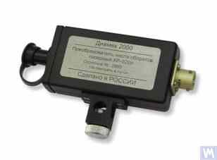
चित्र 4.11: "डायमेक्स" द्वारा निर्मित फेज एंगल सेंसर"
एक अन्य उदाहरण के रूप में, चित्र 4.12 एलएलसी "किनेमेटिक्स" (वाइब्रोमेरा) द्वारा कार्यान्वित एक मॉडल को दर्शाता है, जो चरण कोण सेंसर के रूप में चीन में निर्मित DT 2234C मॉडल के लेजर टैकोमीटर का उपयोग करता है। इस सेंसर के स्पष्ट लाभों में शामिल हैं:
- एक विस्तृत परिचालन सीमा, जो प्रति मिनट 2.5 से 99,999 क्रांतियों तक रोटर घूर्णन आवृत्ति को मापने की अनुमति देती है, जिसका संकल्प एक क्रांति से कम नहीं है;
- डिजिटल प्रदर्शन;
- माप के लिए टैकोमीटर स्थापित करने में आसानी;
- सुलभता और कम बाज़ार लागत;
- संतुलन मशीन की मापन प्रणाली में एकीकरण के लिए संशोधन की सापेक्ष सरलता।
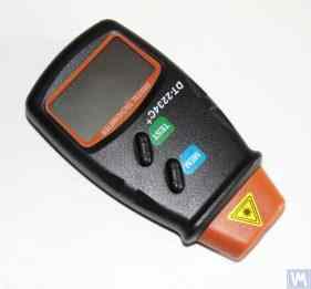
चित्र 4.12: लेजर टैकोमीटर मॉडल DT 2234C
कुछ मामलों में, जब किसी कारण से ऑप्टिकल लेजर सेंसर का उपयोग अवांछनीय हो, तो उन्हें प्रेरणिक गैर-संपर्क विस्थापन सेंसर से प्रतिस्थापित किया जा सकता है, जैसे कि पहले उल्लेखित ISAN E41A मॉडल या अन्य निर्माताओं के समान उत्पाद।
4.3. कंपन सेंसर में सिग्नल प्रोसेसिंग विशेषताएँ
संतुलन उपकरणों में कंपन संकेत के घूर्णी घटक के आयाम और चरण के सटीक माप के लिए, हार्डवेयर और सॉफ़्टवेयर प्रसंस्करण उपकरणों के संयोजन का आमतौर पर उपयोग किया जाता है। ये उपकरण सक्षम करते हैं:
- सेंसर के एनालॉग सिग्नल का ब्रॉडबैंड हार्डवेयर फ़िल्टरिंग;
- सेंसर के एनालॉग सिग्नल का प्रवर्धन;
- एनालॉग सिग्नल का एकीकरण और/या दोहरा एकीकरण (यदि आवश्यक हो);
- ट्रैकिंग फ़िल्टर का उपयोग करके एनालॉग सिग्नल की नैरोबैंड फ़िल्टरिंग;
- सिग्नल का एनालॉग-टू-डिजिटल रूपांतरण;
- डिजिटल सिग्नल की तुल्यकालिक फ़िल्टरिंग;
- डिजिटल सिग्नल का हार्मोनिक विश्लेषण.
4.3.1. ब्रॉडबैंड सिग्नल फ़िल्टरिंग
यह प्रक्रिया कंपन सेंसर सिग्नल को डिवाइस की आवृत्ति सीमा के निचले और ऊपरी दोनों छोरों पर उत्पन्न होने वाले संभावित अवरोधों से मुक्त करने के लिए आवश्यक है। बैलेंसिंग मशीन के मापन उपकरण के लिए बैंड-पास फ़िल्टर की निचली सीमा 2-3 हर्ट्ज़ और ऊपरी सीमा 50 (100) हर्ट्ज़ निर्धारित करना उचित है। "निचली" फ़िल्टरिंग विभिन्न प्रकार के सेंसर मापन एम्पलीफायरों के आउटपुट पर उत्पन्न होने वाले निम्न-आवृत्ति शोर को दबाने में सहायक होती है। "ऊपरी" फ़िल्टरिंग संयोजन आवृत्तियों और मशीन के अलग-अलग यांत्रिक घटकों के संभावित अनुनादी कंपनों के कारण होने वाले अवरोधों को समाप्त करती है।
4.3.2. सेंसर से एनालॉग सिग्नल का प्रवर्धन
यदि बैलेंसिंग मशीन के मापन प्रणाली की संवेदनशीलता बढ़ाने की आवश्यकता हो, तो कंपन सेंसर से मापन इकाई के इनपुट तक जाने वाले संकेतों को प्रवर्धित किया जा सकता है। स्थिर लाभ वाले मानक प्रवर्धन और बहु-चरण प्रवर्धन, जिनका लाभ सेंसर से प्राप्त वास्तविक संकेत स्तर के आधार पर प्रोग्राम द्वारा बदला जा सकता है, दोनों का उपयोग किया जा सकता है। प्रोग्रामेबल बहु-चरण प्रवर्धन का एक उदाहरण LLC "L-Card" द्वारा निर्मित E154 या E14-140 जैसे वोल्टेज मापन कन्वर्टर्स में लगे प्रवर्धन हैं।
4.3.3. एकीकरण
जैसा कि पहले उल्लेख किया गया है, संतुलन मशीनों की माप प्रणालियों में कंपन सेंसर संकेतों के हार्डवेयर एकीकरण और/या दोहरे एकीकरण की सिफारिश की जाती है। इस प्रकार, कंपन-त्वरण के समानुपातिक प्रारंभिक एक्सेलेरोमीटर संकेत को कंपन-गति (एकीकरण) या कंपन-विस्थापन (दोहरा एकीकरण) के समानुपातिक संकेत में परिवर्तित किया जा सकता है। इसी तरह, एकीकरण के बाद कंपन-गति सेंसर संकेत को कंपन-विस्थापन के समानुपातिक संकेत में परिवर्तित किया जा सकता है।
4.3.4. ट्रैकिंग फ़िल्टर का उपयोग करके एनालॉग सिग्नल की नैरोबैंड फ़िल्टरिंग
संतुलन मशीनों के मापन प्रणालियों में कंपन सिग्नल प्रोसेसिंग की गुणवत्ता में सुधार और हस्तक्षेप को कम करने के लिए नैरोबैंड ट्रैकिंग फिल्टर का उपयोग किया जा सकता है। इन फिल्टरों की केंद्रीय आवृत्ति रोटर के घूर्णन सेंसर सिग्नल का उपयोग करके संतुलित रोटर की घूर्णन आवृत्ति के अनुरूप स्वचालित रूप से समायोजित हो जाती है। ऐसे फिल्टर बनाने के लिए "MAXIM" द्वारा निर्मित MAX263, MAX264, MAX267 और MAX268 जैसे आधुनिक एकीकृत परिपथों का उपयोग किया जा सकता है।
4.3.5. सिग्नलों का एनालॉग-टू-डिजिटल रूपांतरण
एनालॉग-टू-डिजिटल रूपांतरण एक महत्वपूर्ण प्रक्रिया है जो आयाम और चरण के मापन के दौरान कंपन सिग्नल प्रोसेसिंग की गुणवत्ता में सुधार सुनिश्चित करती है। यह प्रक्रिया सभी आधुनिक बैलेंसिंग मशीन मापन प्रणालियों में लागू की जाती है। ऐसे एडीसी के प्रभावी कार्यान्वयन का एक उदाहरण एलएलसी "एल-कार्ड" द्वारा निर्मित वोल्टेज मापन कन्वर्टर टाइप E154 या E14-140 है, जिसका उपयोग एलएलसी "किनेमेटिक्स" (वाइब्रोमेरा) द्वारा निर्मित कई बैलेंसिंग मशीन मापन प्रणालियों में किया जाता है। इसके अतिरिक्त, एलएलसी "किनेमेटिक्स" (वाइब्रोमेरा) को "माइक्रोचिप" द्वारा निर्मित PIC18F4620 माइक्रोकंट्रोलर और इसी तरह के उपकरणों पर आधारित सस्ते माइक्रोप्रोसेसर सिस्टम का उपयोग करने का अनुभव है।
4.1.2.2. पीजोइलेक्ट्रिक एक्सेलेरोमीटर पर आधारित कंपन वेग सेंसर
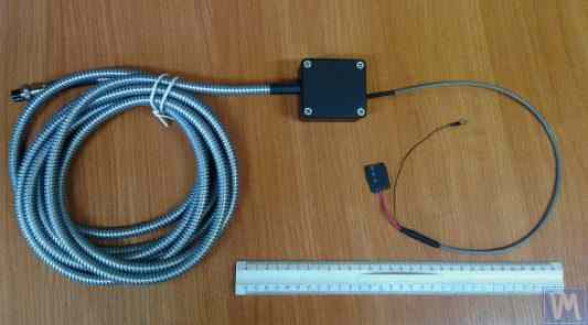
इस प्रकार का सेंसर एक मानक पीजोइलेक्ट्रिक एक्सेलेरोमीटर से इस मायने में भिन्न होता है कि इसके आवरण में एक अंतर्निर्मित चार्ज एम्पलीफायर और इंटीग्रेटर होता है, जो इसे कंपन वेग के समानुपाती सिग्नल उत्पन्न करने में सक्षम बनाता है। उदाहरण के लिए, घरेलू निर्माताओं (ZETLAB कंपनी और LLC "Vibropribor") द्वारा निर्मित पीजोइलेक्ट्रिक कंपन वेग सेंसर चित्र 4.6 और 4.7 में दिखाए गए हैं।
चित्र 4.6. ZETLAB (रूस) द्वारा मॉडल AV02 सेंसर
चित्र 4.7. एलएलसी "वाइब्रोप्रिबोर" द्वारा निर्मित मॉडल डीवीएसटी 2 सेंसर।"
ऐसे सेंसर विभिन्न उत्पादकों (घरेलू और विदेशी दोनों) द्वारा निर्मित किए जाते हैं और वर्तमान में विशेष रूप से पोर्टेबल कंपन उपकरणों में व्यापक रूप से उपयोग किए जाते हैं। इन सेंसरों की लागत काफी अधिक होती है और घरेलू निर्माताओं से भी प्रत्येक सेंसर की कीमत 20,000 से 30,000 रूबल तक हो सकती है।
4.1.3. विस्थापन सेंसर
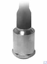
संतुलन मशीनों के मापन प्रणालियों में, गैर-संपर्क विस्थापन सेंसर – संधारित्र या प्रेरक – का भी उपयोग किया जा सकता है। ये सेंसर स्थिर मोड में कार्य कर सकते हैं, जिससे 0 हर्ट्ज़ से शुरू होने वाली कंपन प्रक्रियाओं का रिकॉर्ड रखा जा सकता है। इनका उपयोग 120 आरपीएम और उससे कम घूर्णन गति वाले कम गति वाले रोटरों के संतुलन के मामले में विशेष रूप से प्रभावी हो सकता है। इन सेंसरों के रूपांतरण गुणांक 1000 mV/mm और उससे अधिक तक पहुँच सकते हैं, जो अतिरिक्त प्रवर्धन के बिना भी विस्थापन को मापने में उच्च सटीकता और रिज़ॉल्यूशन प्रदान करते हैं। इन सेंसरों का एक स्पष्ट लाभ इनकी अपेक्षाकृत कम लागत है, जो कुछ घरेलू निर्माताओं के लिए 1000 रूबल से अधिक नहीं होती है। संतुलन मशीनों में इन सेंसरों का उपयोग करते समय, यह ध्यान रखना महत्वपूर्ण है कि सेंसर के संवेदनशील तत्व और कंपन करने वाली वस्तु की सतह के बीच नाममात्र कार्यशील अंतर सेंसर कॉइल के व्यास द्वारा सीमित होता है। उदाहरण के लिए, चित्र 4.8 में दिखाए गए सेंसर, "TEKO" द्वारा निर्मित ISAN E41A मॉडल के लिए, निर्दिष्ट कार्यशील अंतराल आमतौर पर 3.8 से 4 मिमी होता है, जो कंपन करने वाली वस्तु के विस्थापन को ±2.5 मिमी की सीमा में मापने की अनुमति देता है।
चित्र 4.8. TEKO (रूस) द्वारा इंडक्टिव विस्थापन सेंसर मॉडल ISAN E41A
4.1.4. बल संवेदक
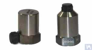
जैसा कि पहले उल्लेख किया गया है, हार्ड बेयरिंग संतुलन मशीनों पर स्थापित मापन प्रणालियों में बल सेंसर का उपयोग किया जाता है। ये सेंसर, विशेष रूप से निर्माण की सादगी और अपेक्षाकृत कम लागत के कारण, आमतौर पर पिएज़ोइलेक्ट्रिक बल सेंसर होते हैं। ऐसे सेंसर के उदाहरण चित्र 4.9 और 4.10 में दिखाए गए हैं।
चित्र 4.9. काइनेमेटिका एलएलसी द्वारा फोर्स सेंसर एसडी 1
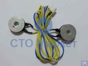
चित्र 4.10: ऑटोमोटिव बैलेंसिंग मशीनों के लिए फोर्स सेंसर, "एसटीओ मार्केट" द्वारा बेचा गया।"
स्ट्रेन गेज बल सेंसर, जिन्हें घरेलू और विदेशी उत्पादकों की एक विस्तृत श्रृंखला द्वारा निर्मित किया जाता है, का उपयोग हार्ड बेयरिंग संतुलन मशीनों के समर्थन में सापेक्ष विकृतियों को मापने के लिए भी किया जा सकता है।
4.4. संतुलन मशीन, "बैलेंससेट 2" की मापन प्रणाली की कार्यात्मक योजना"
"बैलेंसेट 2" मापन प्रणाली, बैलेंसिंग मशीनों में मापन और गणना कार्यों को एकीकृत करने का एक आधुनिक दृष्टिकोण प्रस्तुत करती है। यह प्रणाली प्रभाव गुणांक विधि का उपयोग करके सुधारात्मक भार की स्वचालित गणना प्रदान करती है और इसे विभिन्न मशीन विन्यासों के लिए अनुकूलित किया जा सकता है।
इस प्रणाली में सिग्नल कंडीशनिंग, एनालॉग-टू-डिजिटल रूपांतरण, डिजिटल सिग्नल प्रोसेसिंग और स्वचालित गणना एल्गोरिदम शामिल हैं। यह प्रणाली दो-स्तरीय और बहु-स्तरीय संतुलन दोनों स्थितियों को उच्च परिशुद्धता के साथ संभाल सकती है।
4.5. रोटर संतुलन में प्रयुक्त सुधार भारों के मापदंडों की गणना
सुधारात्मक भारों की गणना प्रभाव गुणांक विधि पर आधारित है, जो यह निर्धारित करती है कि रोटर विभिन्न तलों में परीक्षण भारों के प्रति कैसी प्रतिक्रिया देता है। यह विधि सभी आधुनिक संतुलन प्रणालियों का मूलभूत आधार है और कठोर एवं लचीले दोनों प्रकार के रोटरों के लिए सटीक परिणाम प्रदान करती है।
4.5.1. द्वि-समर्थन रोटरों का संतुलन कार्य और इसके समाधान के तरीके
दोहरे समर्थन वाले रोटरों (सबसे आम विन्यास) के लिए, संतुलन कार्य में दो सुधारात्मक भार निर्धारित करना शामिल है - प्रत्येक सुधार तल के लिए एक। प्रभाव गुणांक विधि निम्नलिखित दृष्टिकोण का उपयोग करती है:
- प्रारंभिक माप (रन 0): बिना किसी परीक्षण भार के कंपन को मापें
- पहला परीक्षण (रन 1): प्लेन 1 में ज्ञात परीक्षण भार जोड़ें, प्रतिक्रिया मापें
- दूसरा परीक्षण (रन 2): परीक्षण भार को तल 2 पर ले जाएं, प्रतिक्रिया मापें
- गणना: सॉफ्टवेयर मापी गई प्रतिक्रियाओं के आधार पर स्थायी सुधार भार की गणना करता है।
गणितीय आधार में परीक्षण भार के प्रभावों को दोनों तलों में आवश्यक सुधारों से संबंधित रैखिक समीकरणों की एक प्रणाली को एक साथ हल करना शामिल है।
आंकड़े 3.26 और 3.27 खराद बेड का उपयोग करने के उदाहरण दिखाएं, जिसके आधार पर ऑगर्स को संतुलित करने के लिए एक विशेष हार्ड बेयरिंग मशीन और बेलनाकार रोटर के लिए एक सार्वभौमिक सॉफ्ट बेयरिंग बैलेंसिंग मशीन का निर्माण किया गया था। DIY निर्माताओं के लिए, ऐसे समाधान न्यूनतम समय और लागत के साथ संतुलन मशीन के लिए एक कठोर समर्थन प्रणाली बनाने की अनुमति देते हैं, जिस पर विभिन्न प्रकार के समर्थन स्टैंड (हार्ड बेयरिंग और सॉफ्ट बेयरिंग दोनों) लगाए जा सकते हैं। इस मामले में निर्माता के लिए मुख्य कार्य मशीन गाइड की ज्यामितीय परिशुद्धता सुनिश्चित करना (और यदि आवश्यक हो तो बहाल करना) है जिस पर समर्थन स्टैंड आधारित होंगे। DIY उत्पादन स्थितियों में, गाइड की आवश्यक ज्यामितीय सटीकता को बहाल करने के लिए आमतौर पर बारीक स्क्रैपिंग का उपयोग किया जाता है।
चित्र 3.28 दो चैनलों से बने एक इकट्ठे बिस्तर का एक संस्करण दिखाता है। इस बिस्तर के निर्माण में, अलग किए जा सकने वाले बोल्ट वाले कनेक्शन का उपयोग किया जाता है, जिससे अतिरिक्त तकनीकी संचालन के बिना असेंबली के दौरान बिस्तर के विरूपण को कम से कम या पूरी तरह से समाप्त किया जा सकता है। निर्दिष्ट बिस्तर के गाइड की उचित ज्यामितीय सटीकता सुनिश्चित करने के लिए, उपयोग किए गए चैनलों के शीर्ष फ्लैंग्स की यांत्रिक प्रसंस्करण (पीसना, बारीक मिलिंग) की आवश्यकता हो सकती है।
आंकड़े 3.29 और 3.30 वेल्डेड बेड की विविधताएं भी दो चैनलों से बनी हैं। ऐसे बेड के लिए विनिर्माण प्रौद्योगिकी में कई अतिरिक्त संचालन की आवश्यकता हो सकती है, जैसे वेल्डिंग के दौरान होने वाले आंतरिक तनाव को दूर करने के लिए गर्मी उपचार। इकट्ठे बेड के साथ, वेल्डेड बेड के गाइड की उचित ज्यामितीय सटीकता सुनिश्चित करने के लिए, उपयोग किए गए चैनलों के शीर्ष फ्लैंग्स की यांत्रिक प्रसंस्करण (पीसना, बारीक मिलिंग) की योजना बनाई जानी चाहिए।
4.5.2. बहु-समर्थन रोटरों के गतिशील संतुलन के लिए कार्यप्रणाली
मल्टी-सपोर्ट रोटर्स (तीन या चार बेयरिंग पॉइंट्स) के लिए अधिक जटिल बैलेंसिंग प्रक्रियाओं की आवश्यकता होती है। प्रत्येक सपोर्ट पॉइंट समग्र डायनामिक व्यवहार में योगदान देता है, और करेक्शन में सभी तलों के बीच की परस्पर क्रियाओं को ध्यान में रखना आवश्यक है।
यह पद्धति दो-तल दृष्टिकोण को निम्नलिखित तरीकों से विस्तारित करती है:
- सभी सपोर्ट बिंदुओं पर कंपन का मापन
- कई परीक्षण भार स्थितियों का उपयोग करना
- रैखिक समीकरणों की बड़ी प्रणालियों को हल करना
- सुधार भार वितरण को अनुकूलित करना
कार्डन शाफ्ट और इसी तरह के लंबे रोटरों के लिए, यह दृष्टिकोण आमतौर पर आईएसओ गुणवत्ता ग्रेड जी6.3 या उससे बेहतर के अनुरूप अवशिष्ट असंतुलन स्तर प्राप्त करता है।
4.5.3. बहु-समर्थन रोटरों के संतुलन के लिए कैलकुलेटर
तीन और चार सपोर्ट वाले रोटर कॉन्फ़िगरेशन के लिए विशेष गणना एल्गोरिदम विकसित किए गए हैं। ये कैलकुलेटर Balanset-4 सॉफ़्टवेयर में कार्यान्वित किए गए हैं और जटिल रोटर ज्यामिति को स्वचालित रूप से संभाल सकते हैं।
ये कैलकुलेटर निम्नलिखित बातों का ध्यान रखते हैं:
- परिवर्तनीय समर्थन कठोरता
- सुधार तलों के बीच क्रॉस-युग्मन
- सुगमता के लिए भार स्थान का अनुकूलन
- गणना किए गए परिणामों का सत्यापन
5. संतुलन मशीनों के संचालन और सटीकता की जाँच के लिए अनुशंसाएँ
किसी बैलेंसिंग मशीन की सटीकता और विश्वसनीयता कई कारकों पर निर्भर करती है, जिनमें उसके यांत्रिक घटकों की ज्यामितीय सटीकता, सपोर्ट की गतिशील विशेषताएं और मापन प्रणाली की परिचालन क्षमता शामिल हैं। इन मापदंडों का नियमित सत्यापन बैलेंसिंग की गुणवत्ता को बनाए रखता है और उत्पादन को प्रभावित करने से पहले संभावित समस्याओं की पहचान करने में मदद करता है।
5.1. मशीन की ज्यामितीय सटीकता की जाँच
ज्यामितीय सटीकता सत्यापन में सपोर्ट के संरेखण, गाइड की समानांतरता और स्पिंडल असेंबली की संकेंद्रता की जाँच शामिल है। सटीकता बनाए रखने के लिए ये जाँचें प्रारंभिक सेटअप के दौरान और संचालन के दौरान समय-समय पर की जानी चाहिए।
5.2. मशीन की गतिशील विशेषताओं की जाँच
गतिशील विशेषताओं के सत्यापन में सपोर्ट और फ्रेम घटकों की प्राकृतिक आवृत्तियों को मापना शामिल है ताकि यह सुनिश्चित किया जा सके कि वे परिचालन आवृत्तियों से उचित रूप से अलग हैं। इससे अनुनाद संबंधी समस्याओं को रोका जा सकता है जो संतुलन सटीकता को प्रभावित कर सकती हैं।
5.3. मापन प्रणाली की परिचालन क्षमता की जाँच
मापन प्रणाली सत्यापन में सेंसर अंशांकन, चरण संरेखण सत्यापन और सिग्नल प्रोसेसिंग सटीकता जांच शामिल हैं। यह सभी परिचालन गतियों पर कंपन आयाम और चरण के विश्वसनीय मापन को सुनिश्चित करता है।
5.4. ISO 21940-21 (पूर्व में ISO 2953) के अनुसार Accuracy Characteristics की जाँच
ISO 21940-21 (पूर्व में ISO 2953) calibrated test rotors का उपयोग करके balancing machine accuracy को सत्यापित करने के लिए standardized procedures प्रदान करता है। ये procedures machine performance को internationally recognized standards के विरुद्ध validate करने में मदद करती हैं।
साहित्य
- रेशेतोव डीएन (संपादक)। "धातु-काटने वाली मशीन औजारों के विवरण और क्रियाविधियाँ।" मॉस्को: माशिनोस्ट्रोएनी, 1972।
- केलनबर्गर डब्ल्यू. "बेलनाकार सतहों की सर्पिल पिसाई।" मशीनरी, 1963।
- ISO 281 "Rolling Bearings - Dynamic Load Ratings and Rating Life."
- GOST 17383-73 (national standard) "Pulleys for flat drive belts."
- ISO 21940-11 (पूर्व में ISO 1940-1) "Mechanical vibration - Rotor balancing - Part 11: Procedures and tolerances for rotors with rigid behaviour."
- ISO 21940-21 (पूर्व में ISO 2953) "Mechanical vibration - Rotor balancing - Part 21: Description and evaluation of balancing machines."
परिशिष्ट 1: तीन समर्थन शाफ्टों के संतुलन के मापदंडों की गणना के लिए एल्गोरिदम
तीन-समर्थन रोटर संतुलन के लिए तीन अज्ञात राशियों वाले तीन समीकरणों की प्रणाली को हल करना आवश्यक है। यह परिशिष्ट तीन सुधार तलों में सुधारात्मक भार निर्धारित करने के लिए गणितीय आधार और चरण-दर-चरण गणना प्रक्रिया प्रदान करता है।
A1.1. गणितीय आधार
तीन सपोर्ट वाले रोटर के लिए, प्रभाव गुणांक मैट्रिक्स परीक्षण भार प्रभावों को प्रत्येक बेयरिंग स्थान पर कंपन प्रतिक्रियाओं से संबंधित करता है। समीकरण प्रणाली का सामान्य रूप इस प्रकार है:
[V₂] = [A₂₁ A₂₂ A₂₃] [W₂]
[V₃] = [A₃₁ A₃₂ A₃₃] [W₃]
कहाँ:
- वी₁, वी₂, वी₃ सपोर्ट 1, 2 और 3 पर कंपन सदिश
- W₁, W₂, W₃ तल 1, 2 और 3 में सुधार भार
- Aᵢⱼ - भार j और आधार i पर कंपन के बीच संबंध स्थापित करने वाले प्रभाव गुणांक
A1.2. गणना प्रक्रिया
- प्रारंभिक माप: बिना परीक्षण भार के तीनों आधारों पर कंपन आयाम और चरण को रिकॉर्ड करें।
- परीक्षण भार अनुक्रम: ज्ञात परीक्षण भार को क्रमिक रूप से प्रत्येक सुधार तल पर लागू करें और कंपन परिवर्तनों को रिकॉर्ड करें।
- प्रभाव गुणांक की गणना: यह निर्धारित करें कि प्रत्येक परीक्षण भार प्रत्येक सपोर्ट पर कंपन को कैसे प्रभावित करता है।
- मैट्रिक्स समाधान: इष्टतम सुधार भार ज्ञात करने के लिए समीकरणों की प्रणाली को हल करें।
- वजन रखने की जगह: निर्धारित कोणों पर परिकलित भार स्थापित करें।
- सत्यापन: सुनिश्चित करें कि अवशिष्ट कंपन विनिर्देशों के अनुरूप है।
A1.3. तीन-समर्थन वाले रोटरों के लिए विशेष विचार
तीन-समर्थन विन्यास आमतौर पर लंबे कार्डन शाफ्ट के लिए उपयोग किए जाते हैं जहां अत्यधिक विक्षेपण को रोकने के लिए मध्यवर्ती समर्थन की आवश्यकता होती है। मुख्य विचारणीय बिंदु इस प्रकार हैं:
- मध्यवर्ती सपोर्ट की कठोरता समग्र रोटर गतिशीलता को प्रभावित करती है।
- सटीक परिणामों के लिए समर्थन संरेखण महत्वपूर्ण है।
- परीक्षण भार की मात्रा से सभी आधारों पर मापने योग्य प्रतिक्रिया उत्पन्न होनी चाहिए।
- तलों के बीच क्रॉस-युग्मन के लिए सावधानीपूर्वक विश्लेषण की आवश्यकता होती है।
परिशिष्ट 2: चार समर्थन शाफ्टों के संतुलन के मापदंडों की गणना के लिए एल्गोरिदम
चार-समर्थन रोटर संतुलन सबसे जटिल सामान्य विन्यास का प्रतिनिधित्व करता है, जिसके लिए 4x4 मैट्रिक्स प्रणाली के समाधान की आवश्यकता होती है। यह विन्यास कागज मिल रोल, कपड़ा मशीनरी शाफ्ट और भारी औद्योगिक रोटर जैसे बहुत लंबे रोटरों के लिए विशिष्ट है।
A2.1. विस्तारित गणितीय मॉडल
चार-समर्थन प्रणाली चार बेयरिंग स्थानों को ध्यान में रखते हुए अतिरिक्त समीकरणों के साथ तीन-समर्थन मॉडल का विस्तार करती है:
[V₂] = [A₂₁ A₂₂ A₂₃ A₂₄] [W₂]
[V₃] = [A₃₁ A₃₂ A₃₃ A₃₄] [W₃]
[V₄] = [A₄₁ A₄₂ A₄₃ A₄₄] [W₄]
A2.2. अनुक्रमिक परीक्षण भार प्रक्रिया
चार-समर्थन प्रक्रिया के लिए पांच मापन चरणों की आवश्यकता होती है:
- रन 0: चारों आधारों पर प्रारंभिक माप
- रन 1: प्लेन 1 में परीक्षण भार रखें, सभी सपोर्टों को मापें
- रन 2: प्लेन 2 में परीक्षण भार रखें, सभी सपोर्टों को मापें
- रन 3: तल 3 में परीक्षण भार रखें, सभी आधारों को मापें
- रन 4: तल 4 में परीक्षण भार रखें, सभी आधारों को मापें
A2.3. अनुकूलन संबंधी विचार
चार-समर्थन संतुलन अक्सर कई वैध समाधानों की अनुमति देता है। अनुकूलन प्रक्रिया निम्नलिखित बातों पर विचार करती है:
- कुल सुधार भार द्रव्यमान को न्यूनतम करना
- वजन रखने के लिए सुलभ स्थानों को सुनिश्चित करना
- विनिर्माण सहनशीलता और लागतों के बीच संतुलन बनाना
- निर्दिष्ट अवशिष्ट कंपन सीमाओं को पूरा करना
परिशिष्ट 3: बैलेंसर कैलकुलेटर का उपयोग करने हेतु मार्गदर्शिका
बैलेंससेट बैलेंसर कैलकुलेटर परिशिष्ट 1 और 2 में वर्णित जटिल गणितीय प्रक्रियाओं को स्वचालित कर देता है। यह गाइड DIY बैलेंसिंग मशीनों के साथ कैलकुलेटर का प्रभावी ढंग से उपयोग करने के लिए व्यावहारिक निर्देश प्रदान करता है।
A3.1. सॉफ्टवेयर सेटअप और कॉन्फ़िगरेशन
- मशीन की परिभाषा: मशीन की ज्यामिति, सपोर्ट लोकेशन और करेक्शन प्लेन को परिभाषित करें।
- सेंसर अंशांकन: सेंसर के अभिविन्यास और अंशांकन कारकों को सत्यापित करें
- परीक्षण के लिए वजन तैयार करना: रोटर की विशेषताओं के आधार पर उपयुक्त परीक्षण भार की गणना करें।
- सुरक्षा सत्यापन: सुरक्षित परिचालन गति और भार संलग्न करने के तरीकों की पुष्टि करें।
A3.2. मापन अनुक्रम
यह कैलकुलेटर माप की गुणवत्ता पर वास्तविक समय में प्रतिक्रिया और सिग्नल-टू-शोर अनुपात में सुधार के लिए सुझावों के साथ उपयोगकर्ता को माप अनुक्रम के माध्यम से मार्गदर्शन करता है।
A3.3. परिणामों की व्याख्या
यह कैलकुलेटर कई आउटपुट फॉर्मेट प्रदान करता है:
- सुधार आवश्यकताओं को दर्शाने वाले ग्राफिकल वेक्टर डिस्प्ले
- संख्यात्मक भार और कोण विनिर्देश
- गुणवत्ता मापदंड और विश्वास संकेतक
- मापन सटीकता में सुधार के लिए सुझाव
A3.4. सामान्य समस्याओं का निवारण
DIY मशीनों के साथ कैलकुलेटर का उपयोग करते समय आने वाली सामान्य समस्याएं और उनके समाधान:
- परीक्षण के दौरान वजन की अपर्याप्त प्रतिक्रिया: परीक्षण भार की मात्रा बढ़ाएँ या सेंसर माउंटिंग की जाँच करें
- असंगत माप: यांत्रिक अखंडता की पुष्टि करें, अनुनाद स्थितियों की जाँच करें
- खराब सुधार परिणाम: कोण माप की सटीकता सत्यापित करें, क्रॉस-कपलिंग प्रभावों की जाँच करें
- सॉफ्टवेयर त्रुटियाँ: सेंसर कनेक्शन की जांच करें, इनपुट पैरामीटर सत्यापित करें, स्थिर आरपीएम सुनिश्चित करें