← Balanset-1A zināšanu bāze — visas nodaļas
Šī nodaļa ir minimālā teorija, kas nepieciešama, lai apzināti strādātu ar Balanset-1A, nevis vienkārši spiestu pogas.
Kas ir vibrācija un kāpēc mašīna trīc
Jebkura rotora (mulčētāja cilindra, ventilatora lāpstiņriteņa, vārpstas) masas centram ideālā gadījumā jāatrodas tieši uz rotācijas ass. Patiesībā vienmēr ir neliela masas nobīde — disbalanss. Rotoram griežoties, smagā vieta katrā apgriezienā velk to uz sāniem, radot centrbēdzes spēku, kas liek mašīnai vibrēt rotācijas frekvencē.
Svarīgi: nebalanss ir tikai viens no vibrācijas cēloņiem. Mašīna vibrē arī šādu iemeslu dēļ:
- gultņa brīvkustība un nodilums,
- vārpstas nesaosošanās (sajūgi, siksnas),
- plaisas un vaļīgi stiprinājumi (skrūves, rāmis),
- izliekta vārpsta,
- konstrukcijas rezonanse,
- aerodinamiskie un elektromagnētiskie spēki (ventilatori, frekvenču pārveidotāji).
Balansēšana novērš tikai disbalansu. Viss pārējais jāremontē, nevis jābalansē. Tāpēc galvenais noteikums ir šāds: balansēšana nevar salabot bojātu mašīnu.
Kādās vienībās mēra vibrāciju
Balanset-1A mēra vibrācijas ātruma efektīvo vērtību (RMS) vienībās mm/s. Tas ir standarta lielums mašīnas stāvokļa novērtēšanai darba frekvenču diapazonā.
Rupja ātrā novērtējuma skala (balstīta uz ISO 10816/20816, detaļas 6. nodaļa):
| Vibrācijas ātrums (RMS) | Novērtējums |
|---|---|
| līdz 1,4 mm/s | izcili |
| 1,4–2,8 mm/s | labs |
| 2.8 – 4.5 mm/s | pieņemami |
| virs 4,5 mm/s | slikti — nepieciešama rīcība |
Lauksaimniecības tehnikai (mulčētājiem, pļaujmašīnām) robežas ir mīkstākas: līdz 4,8 mm/s ir normāli, līdz 7,1 mm/s uz mīkstiem balstiem, un, ņemot vērā darba apstākļus, “zem 8 mm/s jau ir labi”.
Frekvence, apgriezieni un harmonikas
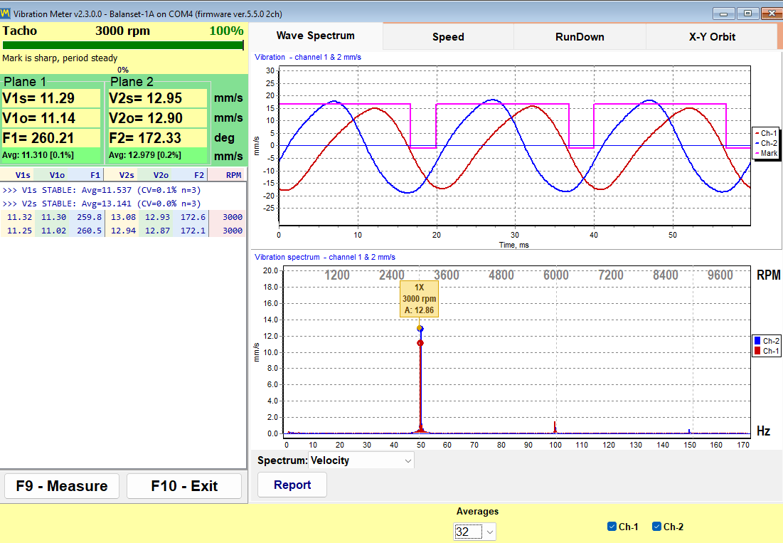
Pieņemsim, ka rotors griežas ar 3000 apgr./min. Tie ir 50 apgriezieni sekundē jeb 50 Hz. Vibrāciju sadala frekvenču komponentēs, kas veido spektru (FFT). Spektrs parāda vibrācijas avotus:
- 1x (rotācijas frekvence) ir klasiska disbalansa pazīme. Balansēšana samazina tieši šo komponenti.
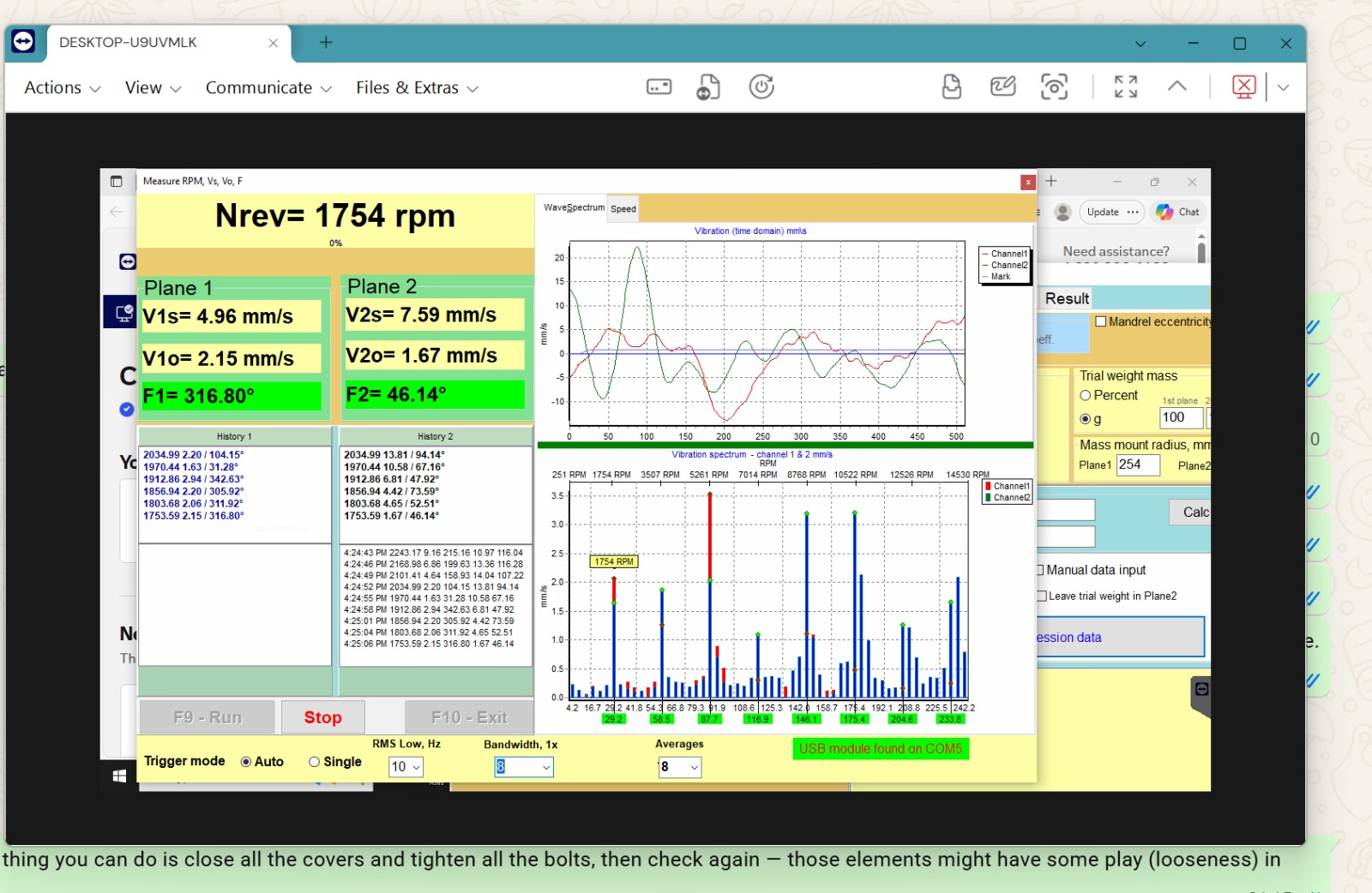
- 2x, 3x (2., 3. harmonika) — biežāk vārpstas nobīde, vaļīgi stiprinājumi, izliekta vārpsta. Ja 2x ir lielāks par 1x — vēl par agru balansēt; vispirms meklējiet nesaosošanos/vaļīgumu.
- Augstas frekvences, “troksnis” — gultņu un zobratu sazobes defekti.
- Zemas frekvences, kas nav saistītas ar apgriezieniem — vaļīgs pamats/stiprinājumi, aerodinamika.
- Elektrotīkla frekvences reizinājumi (piemēram, 6 × 50 Hz = 300 Hz) — elektromagnētiskie traucējumi no frekvenču pārveidotāja. Pārbaude: izslēdziet frekvenču pārveidotāju izskrējiena laikā — ja pīķis pazūd, tas ir elektrisks, nevis mehānisks.
Praktisks tehniskā atbalsta likums: ja spektra pīķis nobīdās proporcionāli mainoties apgriezieniem — tā ir rotācijas harmonika; ja tas paliek nekustīgs — tā ir konstrukcijas rezonanse vai ārējs avots.
Kā tas izskatās ekrānā:
Fāze: smagās vietas virziens
Papildus amplitūdai ierīce mēra fāzi — leņķi starp tahometra impulsu (kad atstarojošā atzīme šķērso lāzera staru) un vibrācijas maksimumu. Fāze parāda, kur atrodas disbalanss. Pēc izmēģinājuma atsvara uzstādīšanas ierīce no amplitūdas un fāzes izmaiņām aprēķina korekcijas atsvara masu un leņķi, izmantojot ietekmes koeficientu metodi.
Praktiskās sekas:
- tahometra atzīmi nedrīkst pielīmēt no jauna starp ieskrējieniem — fāzes “nulle” nobīdās. Pašu tahometru arī nedrīkst pārvietot vai pārvirzīt;
- Apgriezieniem jābūt vienādiem visos sērijas mērījumos;
- fāzei jābūt stabilai no ieskrējiena uz ieskrējienu (izkliede ne vairāk kā ~10–20°). Ja fāze klīst — mērījumam nevar uzticēties; meklējiet mehānisku cēloni vai rezonansi.
Rezonanse: galvenais šķērslis balansēšanai
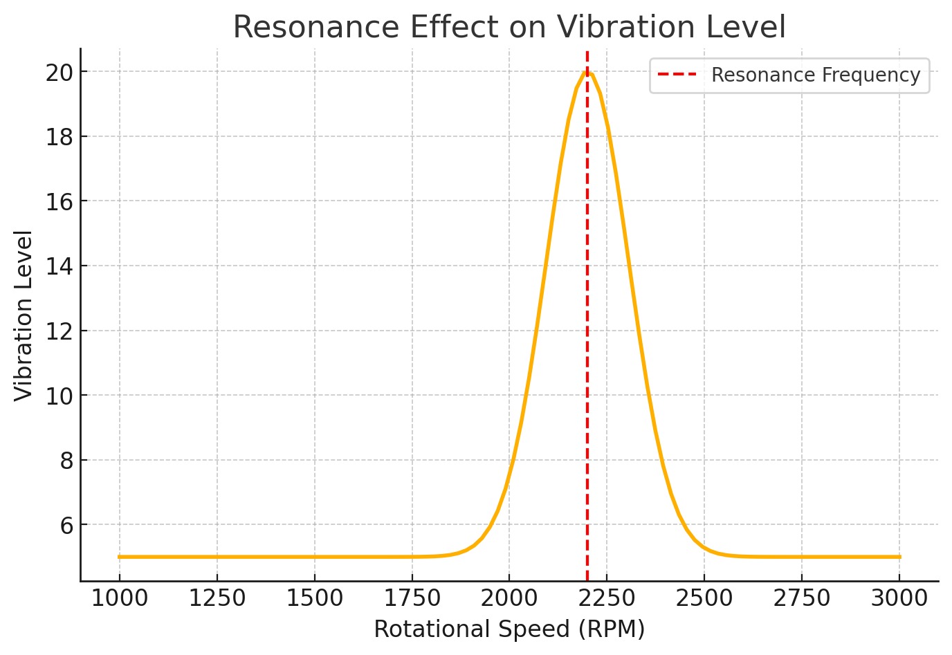
Katrai konstrukcijai (rotors + balsti + rāmis) ir pašfrekvences. Ja darba apgriezieni sakrīt ar pašfrekvenci, rezonanse notiek: vibrācija strauji pieaug, fāze lēkā, ierīces aprēķini pārstāj konverģēt, un “ierīce vienmēr pieprasa vēl vairāk atsvara”.
Rezonanses pazīmes:
- neliela apgriezienu izmaiņa maina vibrāciju vairākkārt;
- pēc aprēķinātā atsvara uzstādīšanas vibrācija pieaug, nevis samazinās;
- amplitūda un fāze ir nestabila nemainītos apstākļos.
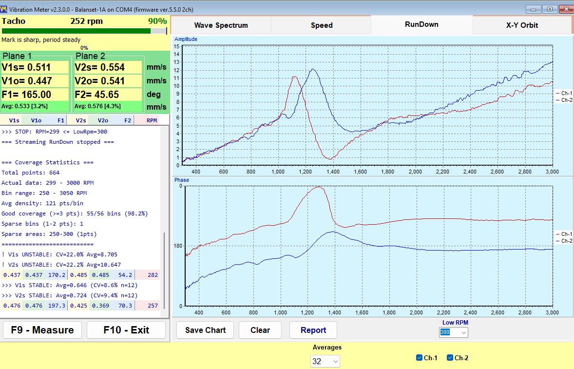
Ko darīt: balansējiet pie citiem apgriezieniem — parasti zem rezonanses. Tipiskā mulčētāju recepte: rupja balansēšana pie 600–900 apgr./min, tad pāreja uz darba apgriezieniem. Jaunākajām programmatūras versijām ir RunDown (izskrējiena) grafiks — iegrieziet rotoru, atslēdziet piedziņu un ierakstiet izskrējienu: pīķi atklāj rezonanses frekvences, un balansēšanas apgriezienus izvēlaties starp tiem.
Reāls piemērs: klientam neizdevās nobalansēt rotoru pie 1600 apgr./min, bet pie 1000 apgr./min tas izdevās. Cēlonis bija rezonanse tuvu 1600 apgr./min.
Linearitāte un kāpēc uzstādāt pusi no masas
Ierīces aprēķins pieņem, ka sistēma ir lineāra: divreiz lielāks atsvars rada divreiz lielāku reakciju. Stingrām mašīnām uz laba pamata tas ir tuvu patiesībai. Taču mulčētājs uz traktora, mašīna uz mīkstiem balstiem vai konstrukcija ar brīvkustību un plaisām uzvedas nelineāri: reakcija uz atsvaru bieži nav proporcionāla.
Tāpēc praksē pārbaudīts likums: uzstādiet 1/2 (sliktām mašīnām 1/3) no aprēķinātās masas un veiciet kontrolizmērījumu. Ierīce pēc tam precizēs atlikumu. Tas ir ātrāk nekā pārmetināt lielu atsvaru, kas “pārsniedza” mērķi.
Statiskais un dinamiskais nebalanss
Statiskais — smagā vieta atrodas rotora vienā pusē. Apturēts rotors uz brīviem balstiem pats no sevis apgāzīsies ar smago pusi uz leju. Koriģē ar vienu atsvaru vienā plaknē.
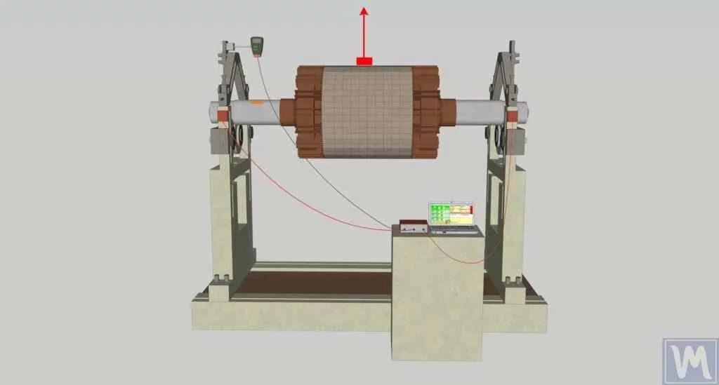
Dinamiskais — smagie punkti dažādos rotora galos un dažādās pusēs. Rotors ne tikai vibrē, bet griežoties “svārstās”. Nepieciešami atsvari divās plaknēs. Statiski to nevar atklāt: pagriežot rotoru par 90° šķiet, ka abi atsvari līdzsvaro viens otru, bet kustībā katrs smagais punkts velk savu virzienu.
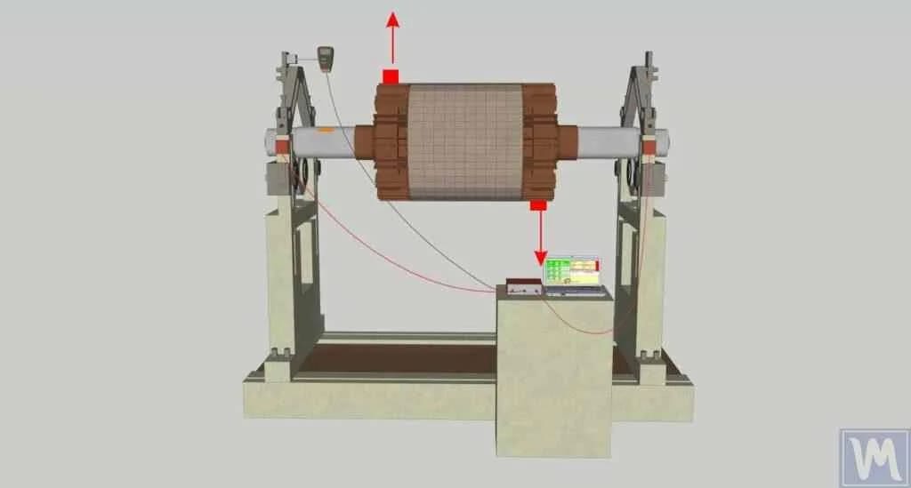
Viena plakne vai divas?
- Viena plakne — šauri rotori (diski, skriemeļi, šauri darbrati). ISO 21940-11 vienkāršais likums: ja rotora platums ir mazāks par pusi no tā diametra (attiecība ~1:2; praksē atbalsts iesaka 1:3) — pietiek ar vienu plakni.
- Divas plaknes — gari rotori (mulčētāju cilindri, vārpstas, kombainu rotori, ventilatori pie 3000 apgr./min un vairāk). Nebalanss rotora abos galos savstarpēji ietekmē viens otru, tāpēc ierīce vienlaikus mēra divus kanālus (sensori X1 un X2) un vienlaikus aprēķina abus atsvarus.
G balansēšanas kvalitātes klases (ISO 1940 / ISO 21940-11)
Atlikušais nebalanss tiek norādīts g-mm pēc G klasēm:
| Pakāpe | Tipisks lietojums |
|---|---|
| G16 | lauksaimniecības tehnika, kardānvārpstas |
| G6.3 | ventilatori, bungas, skriemeļi, vispārējie rotori — visbiežāk lietotā klase |
| G2.5 | turbīnas, elektromotori, darbmašīnas |
| G1 – G0.4 | vārpstas, precīzie rotori |
Jo lielāki apgriezieni un mazāks rotors — jo stingrāka klase. Balanset programmatūrā ir tolerances kalkulators: ievadiet rotora masu, apgriezienus un G klasi — tas atgriež pieļaujamo atlikušo disbalansu g·mm katrai plaknei. Reāls piemērs: 80 kg rotors pie 3000 apgr./min, G6.3 → tolerance ≈ 802 g·mm katrai plaknei.
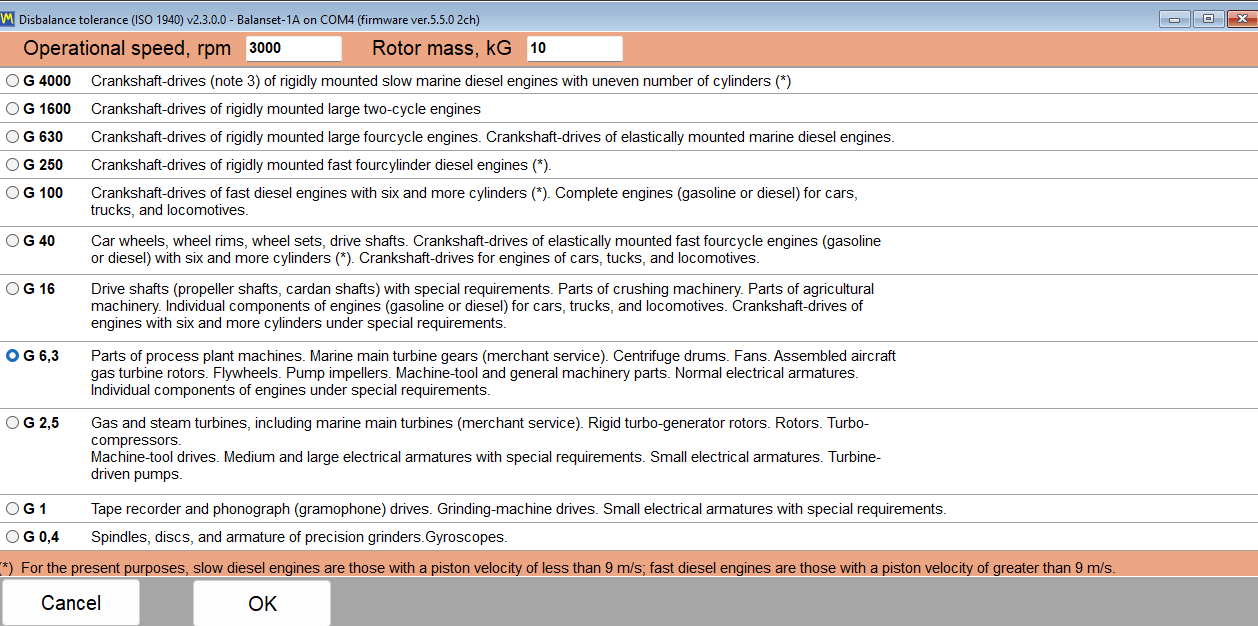
Nejauciet abas novērtēšanas sistēmas:
- mm/s (vibrācijas ātrums) — samontētas mašīnas novērtējums uz vietas saskaņā ar ISO 10816/20816;
- g-mm (atlikušais disbalanss) — paša rotora novērtējums, pēc ISO 1940/21940. Balansēšanas iekārtas strādā g·mm, ekspluatācijas balansēšana parasti seko mm/s.
Mini-glosārijs
| Termiņš | Vienkāršiem vārdiem |
|---|---|
| Nelīdzsvarotība | Rotora masas nobīde attiecībā pret tā rotācijas asi |
| RMS | Vidējais vibrācijas lielums, ko izmanto stāvokļa novērtēšanai |
| 1x, 2x, 3x | Vibrācijas komponentes 1., 2., 3. rotācijas frekvences reizinājumos |
| FFT / spektrs | Vibrācijas sadalījums pa frekvencēm, kas parāda vibrācijas avotus |
| Fāze | Leņķis, kas norāda nebalansa atrašanās vietu |
| Izmēģinājuma svars | Zināma masa, kas uzstādīta, lai ierīce varētu “iepazīt” mašīnas atbildes reakciju |
| Ietekmes koeficienti | Aprēķina metode: kā vibrācija mainījās, uzstādot zināmu atsvaru → cik daudz un kur uzstādīt |
| Rezonanse | apgriezieni sakrīt ar pašfrekvenci; vibrācija strauji pieaug |
| RunDown (izskrējiens) | Vibrācijas ierakstīšana, rotoram brīvi izskrienoties — veids, kā atrast rezonanses |
| g-mm | Nebalansa vienība: masa × tās atrašanās vietas rādiuss |

