Table of Contents
- What is the difference between static and dynamic balance?
- Dynamic Shaft Balancing Instruction
- Description of the Angle Measurement Process for Installing Corrective Weights
- Calculation of the Trial Weight Mass
- Correction Planes Relative to Installed Vibration Sensors
- Two-Plane Dynamic Balancing of a Fan
What is the difference between static and dynamic balance?
Static Balance
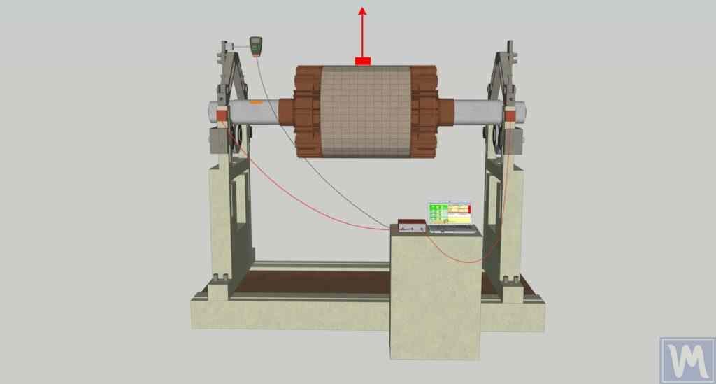
In the first photograph, the rotor is in a state of static imbalance. In this case, the rotor’s center of gravity is offset from the axis of rotation, causing a one-sided force that tries to bring the rotor to a position where its heavier part is down. This imbalance is corrected by adding or removing mass at specific points on the rotor so that the center of gravity coincides with the axis of rotation. When the rotor is in static imbalance, turning it 90 degrees always results in the “heavy point” turning downward.
Static unbalance:
- Occurs when the rotor is stationary.
- The heavy point of the rotor is rotated downwards by gravity.
Static balancing: Used for narrow disk-shaped rotors. It eliminates uneven mass distribution in one plane.
Dynamic Balance
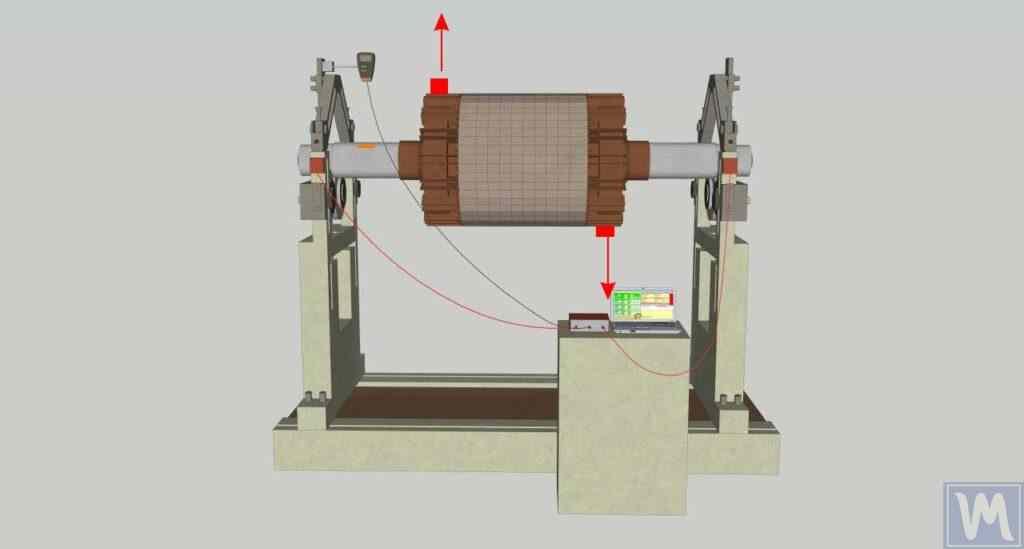
In the second photograph, the rotor is in a state of dynamic imbalance. In this case, the rotor has two different mass displacements in different planes. This not only causes a one-sided force, as in static imbalance, but also moments that create additional vibrations during rotation. In the case of dynamic imbalance, the forces in one plane and in the other plane balance each other. This means that when the rotor is turned 90 degrees, it does not turn “heavy point” downward, which distinguishes it from static imbalance. This type of imbalance can only be corrected dynamically, using a vibration analyzer with a two-plane balancing function.
Dynamic imbalance:
- Appears only when the rotor is rotating.
- It occurs because two unbalanced masses are in different planes along the length of the rotor. When the rotor rotates, these masses create centrifugal forces that do not compensate for each other due to their different locations.
To eliminate the dynamic unbalance, two compensating weights must be installed to create a torque equal and opposite in direction to the torque generated by the unbalanced masses. These compensating weights do not have to be equal in weight or opposite to the original masses, as long as they create the necessary torque to balance the rotor.
Dynamic balancing: Suitable for long double axle rotors. Eliminates uneven weight distribution in two planes, which prevents vibration during rotation.
Dynamic Shaft Balancing Instruction
For dynamic balancing of shafts, we use the Balanset-1A balancing and vibration analysis device.
Balanset -1A được trang bị 2 kênh và được thiết kế để cân bằng động trên hai mặt phẳng . Điều này làm cho nó phù hợp với nhiều ứng dụng khác nhau, bao gồm máy nghiền, quạt, máy nghiền, máy khoan trên máy gặt đập liên hợp, trục, máy ly tâm, tua bin và nhiều loại khác . Tính linh hoạt của nó trong việc xử lý nhiều loại rôto khác nhau làm cho nó trở thành một công cụ thiết yếu cho nhiều ngành công nghiệp.
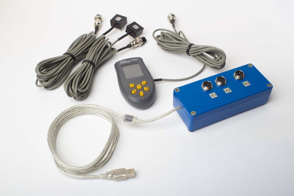
Photo 1: Initial Vibration Measurement

The first photo shows the initial stage of the two-plane dynamic rotor balancing process. The rotor is mounted on the balancing machine. Vibration sensors are connected to the rotor and linked to a computer through a measuring unit. The operator starts the rotor, and the system measures the initial vibrations displayed on the computer screen. This data is used as a baseline for subsequent calculations.
Photo 2: Installing the Calibration Weight and Measuring Vibration Changes
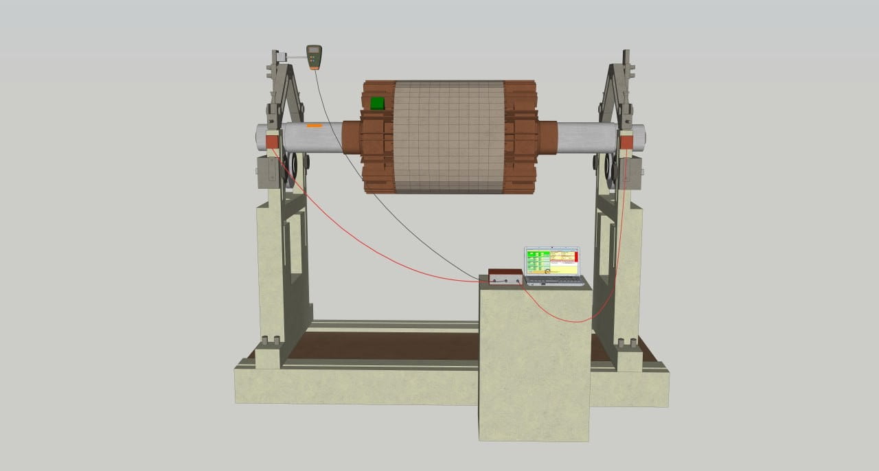
The second photo shows the stage of installing a calibration weight on one side of the rotor in the first plane. A weight of known mass is secured at an arbitrary point on the rotor, on the side of sensor X1. The rotor is started again, and the system measures the vibration changes with the installed weight. This data is recorded by the vibration analyzer to determine the impact of the weight on the vibrations.
Photo 3: Moving the Calibration Weight and Re-Measuring Vibration

The third photo shows the stage of moving the calibration weight to the other side of the rotor. The weight is removed from the initial point and installed at another point on the opposite side of the rotor. The rotor is started again, and the vibration changes with the weight in the new position are measured. This data is also recorded by the portable balancing instrument for further analysis.
Photo 4: Installing the Final Weights and Checking the Balance
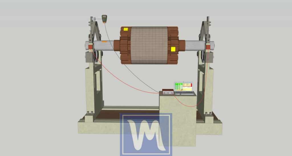
The fourth photo shows the final stage of balancing. Using the measurement data from both sides, the vibration analyzer determines the angle and mass needed to be added for complete rotor balancing. The weights are installed at the points indicated by the instrument on the rotor. After installation, the rotor is started again to check the results. The system shows that the vibration levels have significantly decreased, confirming a successful balance.
Description of the Angle Measurement Process for Installing Corrective Weights
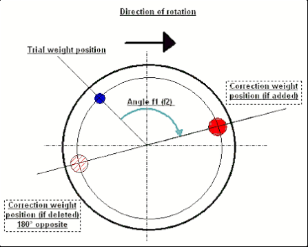
The image shows the method for measuring the angle to install corrective weights during rotor balancing.
Direction of Rotation
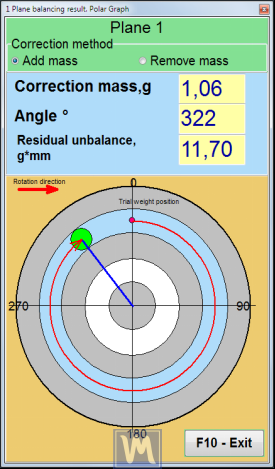
The diagram shows the rotor’s direction of rotation with an arrow. The angle is measured in the direction of the rotor’s rotation.
Trial Weight Position
The trial weight is installed at an arbitrary point on the rotor. This point is called the “Trial weight position”.
Angle Measurement
The diagram shows the angle f1 (or f2), which is measured from the trial weight position in the direction of the rotor’s rotation. This angle indicates where the corrective weight needs to be installed for balancing.
Corrective Weight Position (if added)
The corrective weight is installed at the point marked with a red dot on the diagram. This point is called the “Correction weight position (if added)”. The angle f1 (or f2) is used to determine the exact location of this weight.
Corrective Weight Position (if removed)
If balancing requires weight removal, the corrective weight is removed from the point located 180° opposite the trial weight position. This point is marked with a red dot with diagonal lines on the diagram and is called the “Correction weight position (if deleted; 180° opposite)”.
Calculation of the Trial Weight Mass
The trial weight mass is calculated using the formula:
MA = Mp / (RA * (N/100)^2)
where:
- MA – test weight mass, in grams (g)
- Mp – balanced rotor mass, in grams (g)
- RA – test weight installation radius, in centimeters (cm)
- N – rotor speed, in revolutions per minute (rpm)
Correction Planes Relative to Installed Vibration Sensors
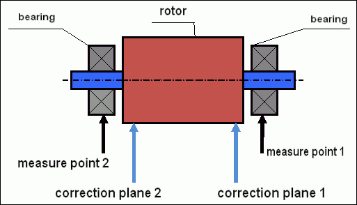

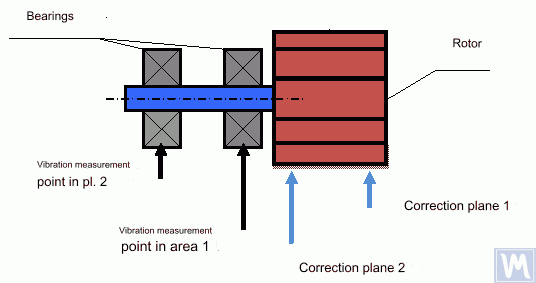
The following photo shows the mulcher rotor and indicates the correction planes and vibration measurement points:
Planes 1 and 2:
Plane 1 (blue 1): Indicates the first plane of rotor balancing, where sensor X1 is installed (closer to the right edge of the photo).
Plane 2 (blue 2): Indicates the second plane of rotor balancing, where sensor X2 is installed (closer to the left edge of the photo).
Installations 1 and 2:
Installation 1 (red 1): The place where the mass correction for the first plane will be carried out.
Installation 2 (red 2): The place where the mass correction for the second plane will be carried out.
This photo demonstrates the process of balancing a mulcher rotor. It shows the zones for installing corrective weights in two planes.
Two-Plane Dynamic Balancing of a Fan
Determining Planes and Installing Sensors
Preparation for Sensor Installation
Clean the surfaces for sensor installation from dirt and oil. Sensors must fit snugly to the surface.
Installing Vibration Sensors

- Vibration sensors are installed on the bearing housing or directly on the bearing housing.
- Sensors are usually installed in two perpendicular radial directions – typically horizontal and vertical directions.
- Vibration measurements are also taken at the machine mounting points to the foundation or frame.
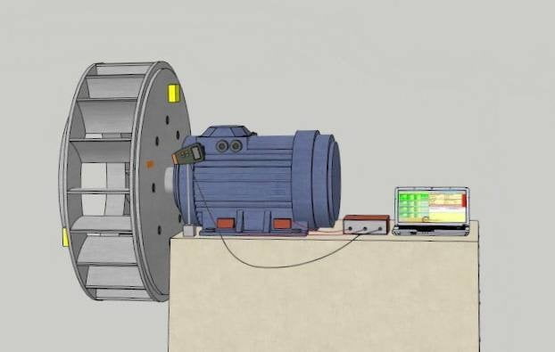
- Sensor 1 (red): Install the sensor closer to the front of the fan, as shown in the image.
- Sensor 2 (green): Install the sensor closer to the rear of the fan.
Connecting Sensors
Connect the sensors to the Balanset-1A vibration analyzer.
Determining Correction Planes
- Plane 1 (red zone): Correction plane located closer to the right side of the fan.
- Plane 2 (green zone): Correction plane located closer to the left side of the fan.
Balancing Process
Initial Vibration Measurement
Start the fan and take initial vibration measurements.
Installing the Trial Weight
Install a trial weight of known mass on the first plane (Plane 1) at an arbitrary point. Start the fan and measure the vibrations.
Move the trial weight to the second plane (Plane 2) also at an arbitrary point. Start the fan again and measure the vibrations.
Data Analysis

Using the obtained data, determine the correction weights and the points where they need to be installed to balance the fan.
Angle Measurement
Determining the Angle for Installing Correction Weights

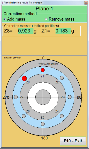

The following image shows the method for determining the angle for installing correction weights:
- Trial weight position (blue dot): Position of the trial weight. This is the reference point, zero degrees.
- Correction weight position (red dot): Position of the correction weight.
- Angle f1 (f2): Angle measured from the trial weight position in the direction of fan rotation.
Installing the Correction Weights
Based on the angles and masses determined by the analyzer, install the correction weights on the first and second planes.
Take vibration measurements after installing the weights and ensure that the vibrations have decreased to an acceptable level.


0 Comment