动态轴平衡平衡说明: 静态与动态, 现场操作规程和 ISO 21940 等级
现场工程师进行转子平衡所需的一切——从不平衡的物理原理到最终验证运行。七步流程、试重公式、校正角度测量和 ISO 公差表。已在风机、粉碎机、破碎机和轴类设备的 2000 多个转子上进行测试。
什么是动态平衡?
动态平衡 动平衡是指在旋转体(转子)以工作转速旋转时,测量并校正其质量分布不均的过程。与校正单个平面内质量偏移的静态平衡不同,动态平衡解决的是多个平面上的不平衡问题。 两个或多个飞机同时, 消除了引起轴承振动的离心力和摇摆力矩。
从200公斤重的粉碎机转子到5克重的牙科钻轴,所有旋转部件都存在一定的残余不平衡。制造公差、材料不一致性、腐蚀和沉积物都会使质心偏离几何旋转轴。其结果是产生离心力,该离心力与转速的平方成正比:转速翻倍,离心力则增加四倍。
转子以 3000 转/分的速度旋转,在 150 毫米半径处仅有 10 克的不平衡量,就会产生约 150 牛顿的旋转力——足以在几周内损坏轴承。动态平衡可以将这种力降低到国际标准(ISO 21940-11,原 ISO 1940)规定的水平,从而将轴承寿命从几个月延长到几年,并减少振动引起的停机时间。
静态平衡与动态平衡
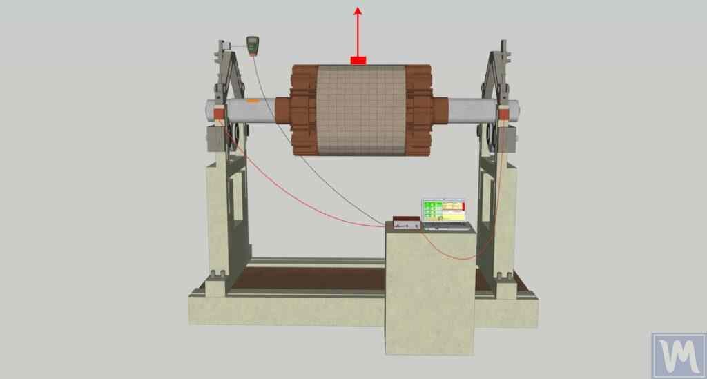
转子的重心偏离旋转轴。 一个平面. 当放置在刀刃状支架上时,较重的一侧会滚到底部——即使不旋转也能察觉到这一点。
更正: 在与重物点相对的单个角度位置上增加或移除质量。一个修正平面就足够了。
适用于 直径大于宽度 7 倍的窄圆盘状零件——飞轮、砂轮、单盘叶轮、锯片、制动盘。
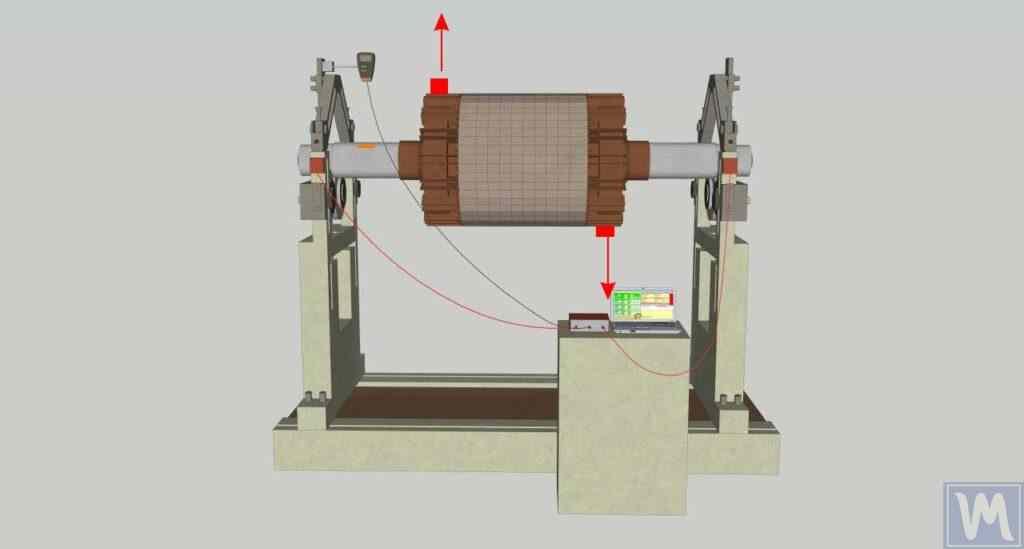
两个(或更多)质量偏移位于 不同的平面 沿转子长度方向。它们在静态情况下可能会相互抵消——转子静止地位于刀刃上——但会产生一个 摇滚情侣 旋转时。如果不旋转,就无法检测或纠正这种相互作用。
更正: 两个补偿配重分别位于两个不同的平面上。该仪器根据影响系数矩阵计算每个平面上的质量和角度。
适用于 细长转子——轴、宽叶轮风扇、粉碎机转子、滚筒、多级泵叶轮、涡轮机。
四种失衡类型
ISO 21940-11区分了四种基本的不平衡模式。了解哪种模式占主导地位有助于选择正确的平衡策略。
实际上,几乎所有现场遇到的转子都存在动态不平衡——力和力矩分量的组合。因此,对于非薄盘状转子,双平面平衡是默认的平衡方法。
何时使用单平面平衡法与双平面平衡法
决定性因素是转子的 几何比长径比 (轴向长度与外径之比)及其运行速度。
| 标准 | 单平面(1个传感器) | 双平面(2个传感器) |
|---|---|---|
| 升/直径比 | 长径比 < 0.14(直径 > 7 倍宽度) | 长径比 ≥ 0.14 |
| 典型部件 | 砂轮、飞轮、单盘叶轮、皮带轮、制动盘、锯片 | 风扇转子、粉碎机、轴、滚筒、多级泵、涡轮机、破碎机 |
| 不平衡类型已纠正 | 仅静态(力) | 静力 + 力偶 + 动力(力 + 力矩) |
| 校正平面 | 1 | 2 |
| 测量运行 | 2(初始 + 1 次试验) | 3(初始 + 2 次试验,每个平面一次) |
| 现场停留时间 | 15-20分钟 | 30-45分钟 |
ISO 21940-11 平衡质量等级
ISO 21940-11(ISO 1940-1 的后续标准)对每一类旋转机械进行分类。 平衡质量等级 G, 定义为转子重心的最大允许速度,单位为毫米/秒。允许的残余比不平衡 eper (单位为g·mm/kg)由料级和运行速度计算得出:
G — 平衡质量等级(例如 6.3 表示 6.3 毫米/秒)
ω — 角速度,弧度/秒
转速 — 运行速度,转/分钟
| 等级 | e·ω,毫米/秒 | 机器类型 |
|---|---|---|
G 0.4 |
0.4 | 陀螺仪,精密磨床主轴 |
G 1.0 |
1.0 | 涡轮增压器、燃气轮机、有特殊要求的小型电枢 |
G 2.5 |
2.5 | 电动机、发电机、中/大型涡轮机、有特殊要求的泵 |
G 6.3 |
6.3 | 风机、泵、工艺机械、飞轮、离心机、通用工业机械 |
G 16 |
16 | 农业机械、破碎机、传动轴(万向轴)、破碎机零部件 |
G 40 |
40 | 乘用车车轮、曲轴总成(批量生产) |
G 100 |
100 | 大型低速船用柴油发动机的曲轴组件 |
实例:风扇转子
离心风扇转子重 80 kg,转速为 1,450 RPM,修正半径为 250 mm。所需等级:G 6.3。
修正半径为 250 毫米时:最大残余质量 = 3320 / 250 = 13.3克 每架飞机
这意味着每个校正平面最多只能保留 13.3 克的不平衡量——大约相当于三个 M6 垫圈的重量。
相关标准: ISO 21940-11 (刚性转子), ISO 21940-12 (柔性转子), ISO 10816-3 (振动严重程度限值), ISO 1940 (前身).
七步现场平衡程序
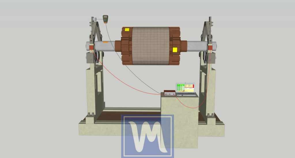
这是利用便携式仪器(例如……)进行双平面场平衡的影响系数法。 Balanset-1A. 同样的逻辑也适用于任何双通道平衡分析仪。

Mt = Mr × K / (Rt × (N/100)²) 其中 Mr = 转子质量 (g),K = 支撑刚度系数 (1–5,平均值取 3),Rt = 安装半径(厘米),N = 转速。或者使用我们的 在线试用体重计算器 — 输入转子参数,即可立即获得推荐质量。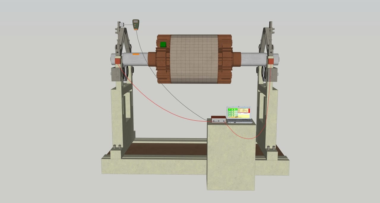

试验重量计算
试验砝码必须足够重,能够产生明显的振动变化,但又不能太重,以免轴承过载或造成危险情况。标准经验公式考虑了转子质量、修正半径、运行速度和支撑刚度:
Mr —转子质量,克
K — 支撑刚度系数(1 = 软支撑,3 = 平均,5 = 刚性基础)
Rt — 试验重量安装半径,厘米
N — 运转速度,RPM
不想手动计算?使用我们的 在线试用体重计算器↗ — 输入转子参数、支撑类型和振动水平,即可立即获得推荐的质量。
实例分析(K = 3,平均刚度)
| 机器 | 转子质量 | 转速 | 半径 | 试验重量(K = 3) |
|---|---|---|---|---|
| 粉碎机转子 | 120公斤 | 2,200 | 30厘米 | 360,000 / (30 × 484) ≈ 25克 |
| 工业风扇 | 80公斤 | 1,450 | 40厘米 | 240,000 / (40 × 210.25) ≈ 29克 |
| 离心机滚筒 | 45公斤 | 3,000 | 15厘米 | 135,000 / (15 × 900) = 10克 |
| 破碎机轴 | 250公斤 | 900 | 25厘米 | 750,000 / (25 × 81) ≈ 370克 |
校正角度测量
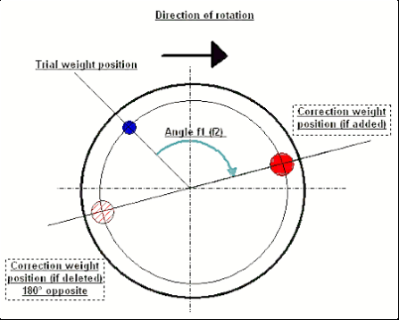
平衡仪每个平面输出两个数值: 质量 (重量)和 角度 (放置位置)。角度始终以试重位置为参考。
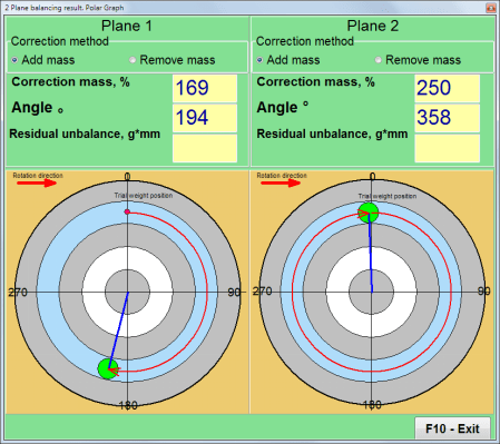
如何测量角度
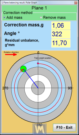
- 参考点(0°): 放置试验砝码的角度位置。在试运行前,请在转子上清晰标记该位置。
- 测量方向: 始终沿转子旋转方向。
- 解读角度: 仪器显示平面 1 的角度 f₁ 和平面 2 的角度 f₂。从试重标记开始,沿旋转方向数出相应的角度——这就是校正砝码放置的位置。
- 如果要切除组织: 将修正量放置在与指示的"添加"位置相反的 180° 位置。
将重量分配到固定位置
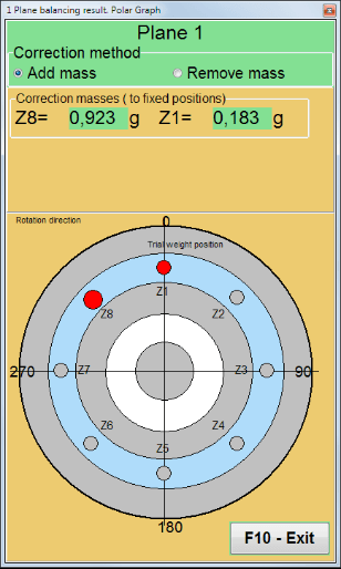
当转子上有预钻孔或固定安装位置(例如风扇叶片螺栓)时,您可能无法将配重放置在精确计算的角度。Balanset-1A 包含一个 权重分割函数您输入两个最近可用位置的角度,软件会将单个校正向量分解为这两个位置上的两个较小权重。组合后的效果与原始向量相匹配。
校正平面和传感器放置
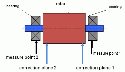
校正平面是指转子上增加或减少质量的轴向位置。传感器测量最近轴承处的振动。以下是一些关键规则:
- 传感器安装在轴承座上 — 尽可能靠近轴承中心线,沿径向(最好是水平方向)。
- 平面 1 对应于传感器 1,, 平面 2 到传感器 2。保持编号一致,否则软件会交换校正平面。
- 最大程度地拉开平面间距: 两个校正平面之间的距离越大,力偶分辨率越高。最小实际间距为轴承跨距的三分之一。
- 选择合适的岗位: 校正平面必须是可以在物理上施加重物的位置——法兰边缘、螺栓圆周、轮辋或焊接表面。
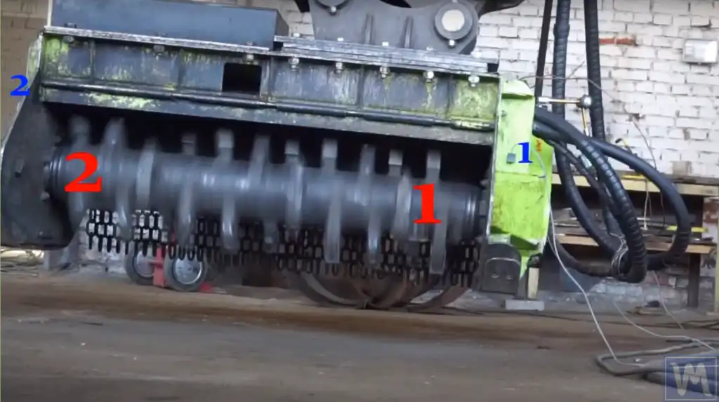
上图所示为一台碎枝机转子,正准备进行双平面平衡。蓝色标记 1 和 2 指示轴承座上的传感器位置。红色标记 1 和 2 指示校正平面——在本例中,即转子本体的法兰端,配重块将焊接于此。
悬臂式(过伸式)转子
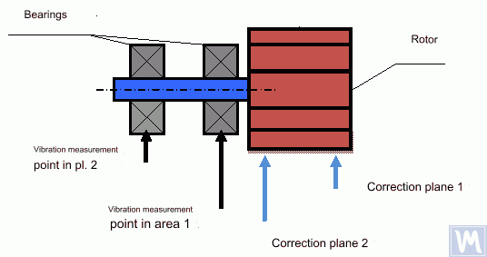
悬臂式转子——例如风扇叶轮、安装在轴承跨距外侧的飞轮以及泵叶轮——需要不同的传感器和校正平面布局。两个校正平面都位于轴承的同一侧,传感器位置必须考虑悬臂质量放大力矩不平衡的影响。
按机器类型划分的应用
重量附加方法
| 方法 | 依恋 | 最适合 | 限值 |
|---|---|---|---|
| 焊接 | 将钢垫圈或钢片点焊到转子轮辋上 | 粉碎机、破碎机、重型工业转子 | 永久性。不使用专用杆,无法用于铝或不锈钢。 |
| 螺栓和螺母 | 螺栓穿过预钻孔,并用锁紧螺母固定 | 风机叶轮、飞轮、联轴器法兰 | 需要利用现有孔洞或进行新钻孔。 |
| 软管夹 | 带配重的夹式不锈钢软管夹 | 现场的轴、滚子、圆柱转子 | 临时或半永久性。检查夹紧扭矩 |
| 螺丝夹 | 预制夹式配重块(例如轮胎配重块) | 风扇叶片、薄轮辋、轻型转子 | 质量范围有限。高转速时可能打滑。 |
| 粘合剂(环氧树脂) | 配重粘在表面上 | 精密转子,洁净环境 | 需要清洁干燥的表面。温度限制约为120°C |
| 材料去除 | 将材料从较重的一侧钻除或磨除 | 涡轮增压器、高速主轴、叶轮 | 永久且精准,但不可逆。适用于增加体重不安全的情况。 |
场平衡中的常见错误
| # | 错误 | 结果 | 使固定 |
|---|---|---|---|
| 1 | 安装在防护罩或盖板上的传感器 | 盖子的共振会使振幅和相位读数失真 → 导致校正错误 | 务必安装在轴承座金属表面上。 |
| 2 | 试用重量太轻 | 相位和振幅变化在噪声范围内 → 影响系数不可靠 | 确保至少一个传感器的振幅变化≥30%或相位偏移≥30° |
| 3 | 跑步间的速度变化 | 振动频率随转速²变化,即使是5%转速的变化也会破坏数据。 | 使用转速表精确跟踪转速。等待转速稳定。 |
| 4 | 忘记取出试验用砝码 | 校正计算包含了试验体重的影响 → 结果毫无意义 | 严格按照流程操作:先移除试用配重,再安装矫正配重。 |
| 5 | 混淆了平面 1 和平面 2 | 校正配重安装位置错误 → 振动加剧 | 清晰标注传感器和平面。传感器 1 → 平面 1,传感器 2 → 平面 2 |
| 6 | 测量与旋转方向相反的角度 | 修正方向为 360° − f 而不是 f → 转子的另一侧 | 开始前请确认旋转方向。始终沿旋转方向测量。 |
| 7 | 运行过程中的热增长 | 冷启动运行期间轴承间隙的变化 → 测量漂移 | 要么在第 0 次运行前进行热身至稳定状态,要么快速完成所有运行(间隔 <5 分钟)。 |
| 8 | 在长转子上使用单平面 | 力偶不平衡未得到纠正 → 远端轴承处的振动甚至可能加剧 | 对于长径比 (L/D) ≥ 0.14 或平面间距较大的转子,应采用双平面平衡法。 |
现场报告:碎枝机转子平衡
机器: Maschio Bisonte 280 型旋耕机,转子重 165 公斤,动力输出轴转速 2100 转/分。客户反映更换 8 个刀片后,机器振动剧烈。
设置: 轴承座上装有两个加速度计,动力输出轴上装有一个激光转速计。Balanset-1A 双平面模式。
运行 0: 传感器 1 = 12.4 毫米/秒 @ 47°,传感器 2 = 8.9 毫米/秒 @ 213°。ISO 10816-3 D 区(危险)。
试运行: 两个平面均使用 500 克试验砝码。响应清晰——两个传感器的振幅变化均大于 60%。
更正: 平面 1:340 克,焊接角度 128°。平面 2:215 克,焊接角度 276°。
验证: 传感器 1 = 0.8 毫米/秒,传感器 2 = 0.6 毫米/秒。ISO A 区(良好)。无需微调。
风扇的双平面动态平衡
工业风机——包括离心式、轴流式和混流式风机——是现场最常见的需要进行动平衡的转子之一。以下步骤将指导您使用 Balanset-1A 对一台径向风机进行实际的双平面动平衡作业。
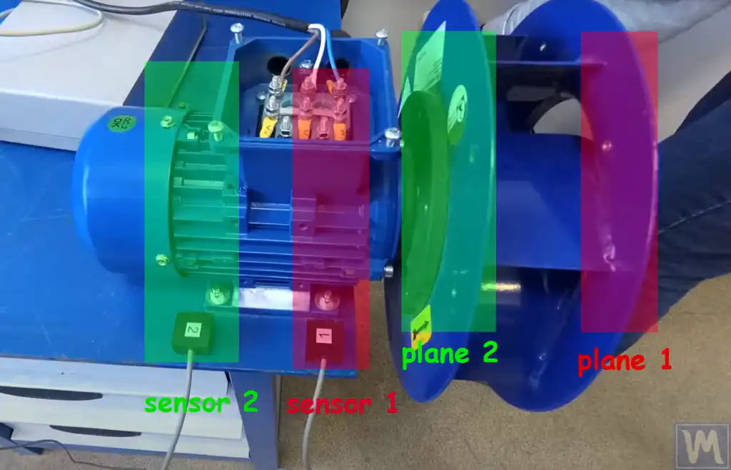
确定平面和安装传感器
安装传感器前,请清除表面污垢和油渍。传感器必须紧密贴合轴承座的金属表面——切勿安装在盖子、防护罩或无支撑的金属板上。
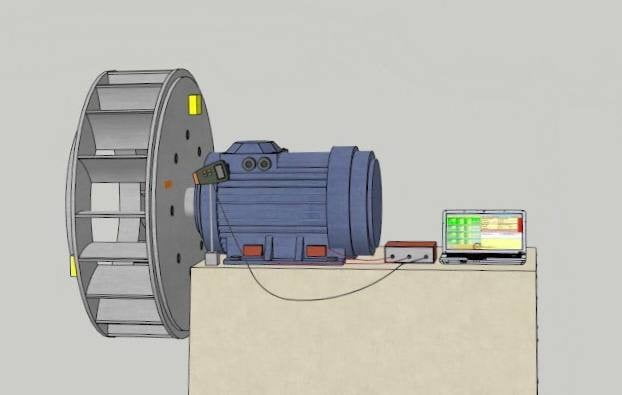
- 传感器 1(红色): 安装位置靠近风扇前部(平面 1 侧)。
- 传感器 2(绿色): 安装位置靠近风扇后部(平面 2 侧)。
- 1号平面(红色区域): 叶轮盘上的修正平面,靠近前端。
- 平面 2(绿色区域): 校正平面更靠近背板或轮毂。
将两个振动传感器和激光转速表连接到 Balanset‑1A。将反光胶带贴在轴或轮毂上作为转速参考。
平衡过程
启动风扇并进行初始振动测量(运行 0)。在平面 1 的任意位置安装已知质量的试重,运行风扇并记录振动变化(运行 1)。将试重移至平面 2 的任意位置,再次运行风扇并记录(运行 2)。Balanset-1A 软件使用这三次测量结果来计算每个平面的修正质量和角度。
风扇校正配重角度测量
角度的测量是从试验砝码的位置沿风扇旋转方向进行的——正如文中所述: 校正角度测量 按照上文所述步骤,标记试验砝码的放置位置(0°参考点),然后沿旋转方向计算所示角度,即可找到校正砝码的位置。

根据软件计算出的角度和质量,在平面 1 和平面 2 上安装校正配重。再次运行风扇,并确认振动已降至可接受的水平。 ISO 21940-11 (通常通用风扇为 G 6.3)。如果残余振动仍然高于目标值,则进行一次微调运行。
常见问题
现场平衡设备
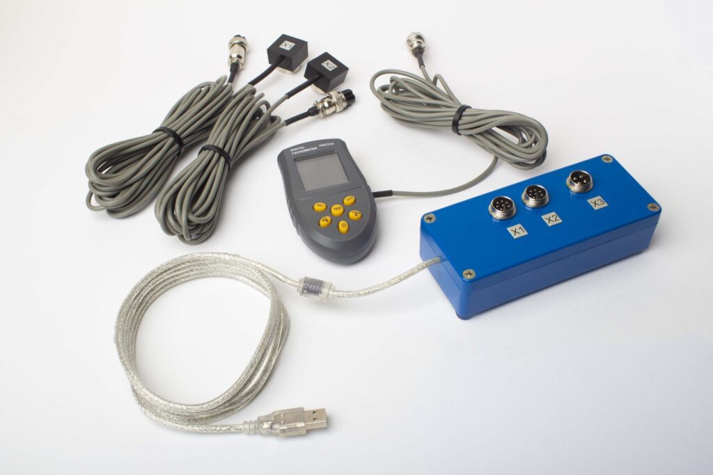
Balanset-1A 是一款双通道便携式仪器,可进行单平面和双平面动平衡,以及振动分析(整体速度、频谱、波形)。它以完整套件的形式发货:
- 2个带磁性安装座的压电式振动传感器
- 带反光胶带的激光转速表(非接触式转速传感器)
- USB测量单元(可连接至任何Windows笔记本电脑)
- 软件:平衡向导、振动计、频谱分析仪
- 包含所有线缆和配件的便携箱
转速测量范围:100–100,000 rpm。振动速度 RMS 测量范围(1× 振动):0.02–80 mm/s。相位精度:±1°。软件包含配重分配、微调运行、公差检查和报告生成功能。全套装备重量不到 5 kg。详见 操作手册第 2 节,了解规格。

Nikolai Shelkovenko
Nikolai Shelkovenko是一名振动分析工程师,也是Vibromera的创始人兼首席执行官。 15年多来,他一直在现场——而非在试验台上——为旋转设备进行平衡:粉碎机、工业风机、破碎机、离心机、轴和主轴。正是这些实际工作催生了Balanset系列仪器——它们被设计为一种专业人员可以随身携带到机器旁、在现场独立使用的工具,而非实验室设备。 Vibromera成立于2017年,自2023年起总部设于葡萄牙波尔图。Balanset系列产品的研发、组装与支持均在此完成。旗舰产品是Balanset-1A,一款用于单平面及双平面平衡和振动诊断的便携式分析仪。 Nikolai亲自参与客户支持工作,处理各种棘手的平衡案例,并参与软件开发。他以任何语言为全球客户提供服务。


0 评论