At a lime production plant, the separator rotor separates the product in the quicklime and slaking process. When the rotor went out of balance and started to vibrate, the whole line was at risk. We balanced it in place with the Balanset-1A portable balancer in about one hour, and the line went back to normal operation.
The machine and the problem
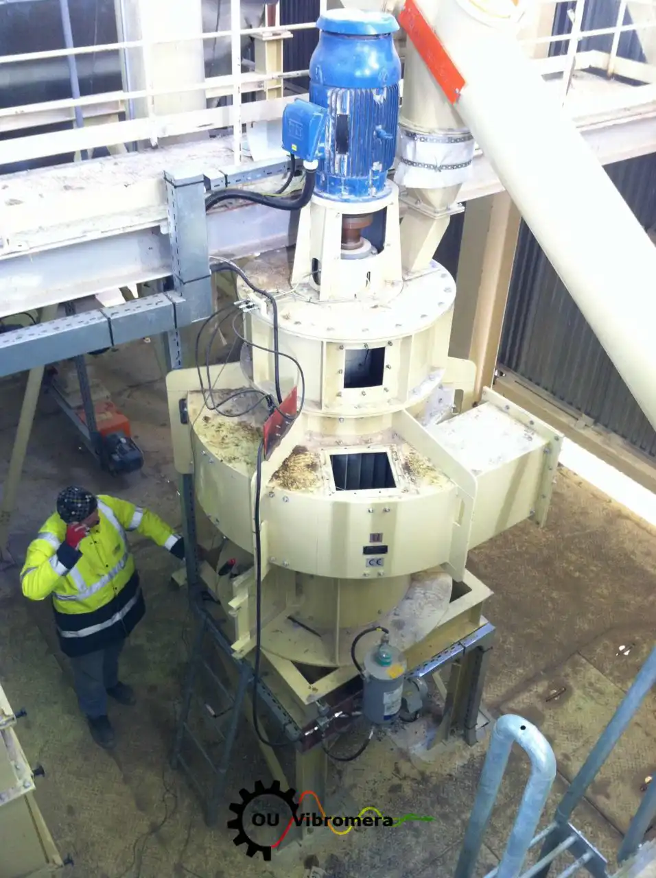
The separator stands on a steel frame inside the plant. Its electric motor sits on top and drives the rotor on a vertical shaft inside the round housing. The rotor began to show signs of unbalance: the vibration rose to a level that threatened the normal operation of the lime line.
Left alone, this leads to production delays or a mechanical failure, so the fix had to be quick. Removing the rotor and sending it to a balancing shop would have meant a long stop, so the rotor was balanced where it works.
How the Balanset-1A was used
The work was done in place, with the rotor in its own bearings and at its working speed. The program leads you through the runs and calculates the correction; the technicians mount the sensors and fix the weights.
Vibration sensors
On a vertical machine "radial" means horizontal. The sensors go on the housing next to the bearings, at right angles to the shaft, on solid metal rather than on thin covers.
Laser tachometer
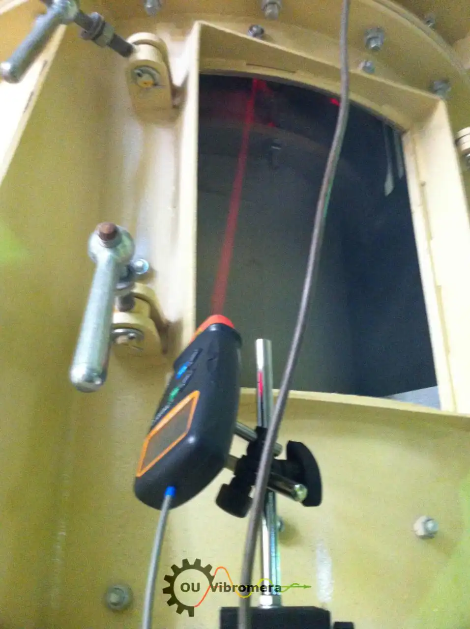
The laser tachometer of the Balanset-1A kit sits on a magnetic stand and looks through an inspection opening in the housing at a reflective mark on the rotor. Once per revolution it gives the rotor speed and the phase reference. Nobody touches the stand until the job is finished: the program counts every angle from this mark.
Run 0
The separator runs at working speed, and the program records the amplitude, phase and speed of the vibration at the running frequency. The live waveform and spectrum show whether the vibration really comes from unbalance: a clear peak at the rotor speed.
Trial run
A trial weight of known mass goes on the rotor at a known radius. It is chosen by force: about 7 % of the rotor's weight as centrifugal force at working speed.
The "First trial weight estimate" in the program or our trial weight calculator gives the mass. The next run shows how the rotor responds to the weight.
Correction
The program calculates the correction mass in grams and its angle from the trial weight position, in the direction of rotation. The trial weight comes off, and the correction weight goes on at the same radius.
Trim run and check
A final run confirms the effect. The program shows the residual vibration and the residual unbalance and, with an ISO 21940-11 tolerance set, a clear pass or fail. If a small addition is needed, it is calculated at once, without a new trial run.
Tips for vertical rotors
- Mount the sensors horizontally, at right angles to the shaft. A sensor on the end face measures axial vibration, and the balancing will not work.
- Keep the background around the reflective mark matte and dark, and shade the tachometer from bright light: glare gives false marks.
- Do not move the mark, the tachometer or the sensors between runs. The program would take the shift for the effect of the weight.
Result
The whole job took about one hour. The excessive vibration was gone, the separator rotor was balanced, and the lime line went back to smooth, efficient operation.
What it gave the plant
- Short downtime: about one hour on site, without removing the rotor.
- No forced stop and no mechanical failure caused by the vibrating rotor.
- A saved record: the program keeps the influence coefficients of the rotor, so a later re-balance can start from them and needs only one measuring run.
About the instrument
Balanset-1A is a two-channel portable balancer and vibration analyzer. It finds the size and position of the unbalance, calculates the correction and checks the result in one session, with the rotor in its own bearings. The same kit serves as a vibration meter and a spectrum analyzer.
More examples: our article on centrifuge balancing and the answers in our FAQ.

Nikolai Shelkovenko
Nikolai Shelkovenko is a vibration analysis engineer and the founder and CEO of Vibromera. For more than 15 years he has balanced rotating equipment in the field rather than on a test bench: mulchers, industrial fans, crushers, centrifuges, shafts and spindles. That work is what the Balanset instruments grew out of — they were designed as a tool a specialist can carry to the machine and use alone, on site, not as laboratory equipment. Vibromera was founded in 2017 and has been based in Porto, Portugal, since 2023. Development, assembly and support of the Balanset line all happen here. The flagship instrument is the Balanset-1A, a portable analyser for single- and two-plane balancing and for vibration diagnostics. Nikolai is personally involved in customer support, in working through difficult balancing cases and in the development of the software. He works with customers worldwide, in any language.