传动轴平衡:综合指南
自行平衡传动轴——无需拆卸,直接在车上进行
Balanset-1A是一款两平面便携式平衡仪:振动传感器、激光转速表和软件集成于一套设备之中。它既能在车上直接平衡传动轴,也能平衡风机、飞轮、破碎机以及其他任何在自身轴承中旋转的转子。提供两年保修,全球DHL / UPS发货,无需订阅。
想象一下,您正在驾驶一辆卡车,突然感到剧烈的震动,或者在加速或换挡时听到巨大的撞击声。这不仅仅是一种干扰,它可能是传动轴不平衡的征兆。对于工程师和技术人员来说,这样的震动和噪音预示着效率的下降、部件的磨损加速,如果不加以处理,还可能造成代价高昂的停机。
正在维修车辆?请参见 无需拆卸的车内传动轴平衡.
车载传动轴平衡:真实案例,逐步讲解
下面的照片来自一次真实的平衡作业,车辆架在举升机上进行。传动轴全程未拆卸:传感器直接安装在车辆本体上,轴由发动机通过传动系带动旋转,校正重块从下方安装。这样传动轴始终处于自身的轴承和工作角度中,因此结果能真实反映整套总成的实际运行状态——这是台架式平衡机无法完全再现的。
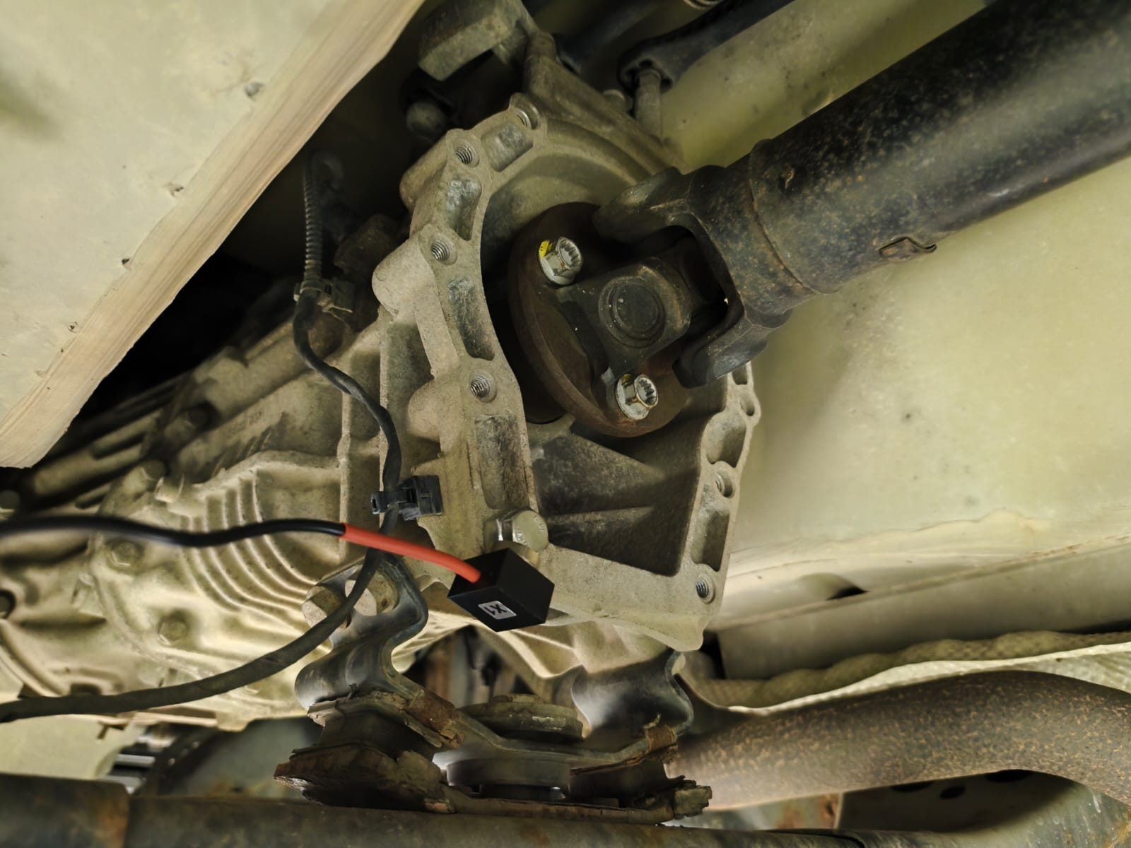
图24. 振动传感器安装在主减速器壳体上,尽可能靠近传动轴支撑轴承。
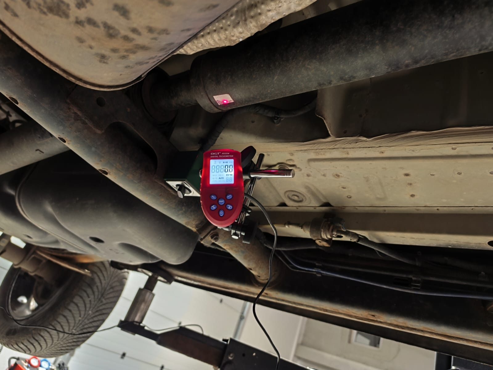
图25. 激光转速表对准轴上的反光胶带——它可同时提供转速和不平衡的相位角。
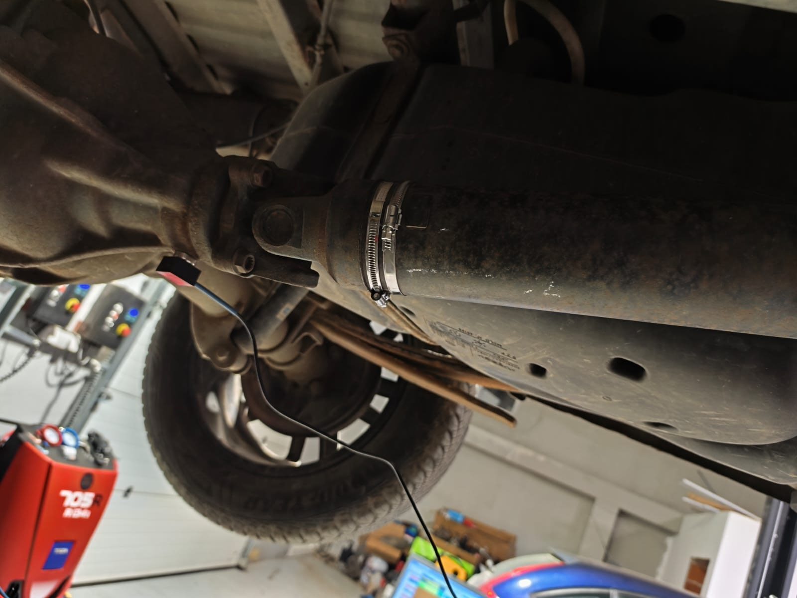
图26. 按软件计算出的角度和质量,用不锈钢管夹将校正配重固定在轴管上。
完整流程——传感器布置、安全试运行、试重和残余振动检查——详见 无需拆卸的车内传动轴平衡.
在本指南中,我们将提供传动轴平衡问题的实用解决方案。您将了解什么是传动轴以及为什么需要进行平衡,识别导致振动或噪音的常见故障,并遵循清晰的分步流程进行动态传动轴平衡。通过应用这些最佳实践,您可以节省维修费用,减少故障排除时间,并确保您的机械或车辆以最小的振动可靠运行。
目录
1.传动轴的类型
万向节驱动装置(传动轴)是一种在万向节中心相交的轴之间传递扭矩的装置,这些轴可以相对移动一定角度。在传统或全轮驱动配置的车辆中,传动轴将扭矩从变速箱(或分动箱)传递到驱动桥。对于全轮驱动车辆,万向节通常将变速箱的从动轴连接到分动箱的驱动轴,并将分动箱的从动轴连接到从动车桥主驱动装置的驱动轴。
安装在车架上的单元(例如变速箱和分动箱)由于其支架和车架本身的变形而彼此相对移动。同时,驱动桥通过悬架连接到车架,由于悬架弹性元件的变形,驱动桥可以相对于车架及其上安装的单元移动。这种移动不仅会改变连接单元的驱动轴的角度,还会改变单元之间的距离。
万向节传动装置存在一个明显的缺点,那就是:两根轴的旋转是不均匀的。如果其中一根轴在匀速旋转,那么另一根轴就无法做到匀速旋转,而且这种不均匀的程度,会随着两轴之间夹角的增大而进一步增大。正是这一局限性,使得万向节传动装置无法应用于许多场合,比如前轮驱动车辆的传动系统,因为在这类应用中,主要的问题在于要把扭矩传递给正在转向的车轮。这一缺点,可以通过在同一根轴上使用两个万向节的方式来部分加以补偿——具体做法是,设置相等的接头角度(γ1 = γ2),并使中间轴两端的轭处于同一个平面内(也就是同相位)。如果两个轭的相位相差90°,那么波动不但不会被抵消,反而会被叠加放大。然而,在那些确实需要匀速旋转的应用场合,通常会改用等速万向节(也就是CV接头)来代替。CV接头是一种设计上更为先进、但同时也更为复杂的方案,用来实现与前者相同的目的。
万向节传动装置可由一个或多个万向节组成,通过传动轴和中间支撑连接。
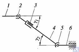
图 1.万向节传动装置示意图:1、4、6 - 传动轴;2、5 - 万向节;3 - 补偿连接;u1、u2 - 轴间夹角
万向节传动装置一般由万向节2和5、驱动轴1、4和6以及补偿连接3组成。有时,驱动轴安装在与车架横梁连接的中间支架上。万向节确保在轴线成一定角度的轴之间传递扭矩。万向节分为非等速万向节和等速万向节。非等速万向节进一步分为弹性万向节和刚性万向节。等速万向节可以是带分度槽的球头万向节、带分度杆的球头万向节和凸轮万向节。它们通常安装在前导控制轮的驱动装置中,其中轴之间的角度可达45°,并且万向节的中心必须与车轮的旋转轴和转向轴的交点重合。
弹性万向节,是依靠连接部件的弹性变形,在轴线相交呈2...3°夹角的两根轴之间传递扭矩的。而刚性的非匀速接头,则是通过刚性部件之间的可动连接,把扭矩从一根轴传递到另一根轴上去的。它由两个轭——也就是图中的3号和5号——所组成,这两个轭的圆柱形孔洞内,装有连接部件——也就是十字轴4号——的四个端部A、B、C、D,并且是通过轴承来安装固定的。这两个轭,分别与轴1和轴2实现刚性连接。轭5,既可以绕十字轴的B–D轴线旋转,同时又能够与十字轴一起,绕A–C轴线旋转,从而能够在两根轴之间的夹角不断发生变化的情况下,依然把旋转运动从一根轴传递到另一根轴上去。
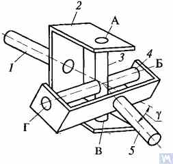
图 2.刚性非匀速万向节示意图
如果轴1绕其轴线转过角度α,那么在同一时间内轴2将转过角度β。轴1和轴2转角之间的关系由以下表达式决定 tanα = tanβ * cosγ,其中γ为两根轴线之间的夹角。该表达式表明,角度β有时小于、等于或大于角度α。这两个角度每隔轴1旋转90°就会相等一次。因此,在轴1匀速旋转的情况下,轴2的角速度是不均匀的,并按正弦规律变化。随着两轴轴线之间夹角γ增大,轴2转动的不均匀程度也会加剧。
如果轴 2 的不均匀旋转传递到机组的轴上,则会在传动过程中产生额外的脉动载荷,并随角度 γ 的增大而增大。为了防止轴 2 的不均匀旋转传递到机组的轴上,在万向节传动中使用了两个万向节。安装时,γ1 和 γ2 的角度相等;固定在非均匀旋转轴 4 上的万向节叉应位于同一平面内。
万向节传动装置主要部件的设计如图3所示。非等速万向节由两个轭杆(1)组成,并通过十字轴(3)连接。其中一个轭杆有时带有法兰,而另一个轭杆则焊接在驱动轴管上,或带有用于连接到驱动轴的花键端(6)(或套筒)。十字轴的耳轴安装在两个轭杆的孔眼中,由滚针轴承(7)支撑。每个轴承都装在一个轴承箱(2)中,并通过一个轴承盖固定在轭杆孔眼中,轴承盖通过两个螺栓固定在轭杆上,螺栓通过垫圈上的卡舌锁定。在某些情况下,轴承通过卡簧固定在轭杆上。为了保持轴承的润滑并防止其受到水和灰尘的侵蚀,轴承配有橡胶自紧密封件。十字轴的内腔通过一个通向轴承的注油嘴注入润滑脂。十字接头通常配有安全阀,以防止因泵入十字接头的润滑脂压力而损坏密封件。花键连接件(6)使用黄油嘴(5)进行润滑。
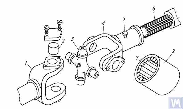
图 3.刚性非匀速万向节的细节
由刚性不等速万向节连接的两轴之间的最大夹角通常不超过20°,因为夹角更大时效率会明显下降。如果两轴轴线之间的夹角在0~2°范围内变化,十字轴的轴颈就会被滚针轴承压出变形,导致万向节很快失效。
在高速履带式车辆的传动中,经常使用齿式联轴器,这种万向节可以在轴线相交角度达 1.5...2° 的轴之间传递扭矩。
传动轴通常使用特殊钢无缝管或焊接管制成管状。万向节、花键套筒或尖端的轭焊接在管子上。为减少传动轴上的横向载荷,在装配万向节时进行动平衡。通过在传动轴上焊接平衡板或有时在万向节轴承盖下安装平衡板来纠正不平衡。在工厂对万向节传动装置进行装配和平衡后,花键连接部件的相对位置通常会用特殊标签进行标记。
万向节传动装置的补偿连接通常采用花键连接形式,允许万向节传动装置部件轴向移动。它包括一个花键头,与万向节传动装置的花键套配合。润滑油通过黄油接头进入花键连接,或在装配时涂抹,并在车辆长期使用后更换。通常会安装一个密封件和一个盖子,以防止润滑脂泄漏和污染。
对于长传动轴,中间支撑通常用于万向节传动。中间支撑通常包括一个用螺栓固定在车架横梁上的支架,支架上的球轴承安装在橡胶弹性圈中。轴承两侧用盖密封,并带有润滑装置。弹性橡胶圈有助于补偿由于车架变形可能造成的装配误差和轴承偏差。
带滚针轴承的万向节(图 4a)由轭、十字架、滚针轴承和密封件组成。带滚针轴承的杯装在十字架的耳轴上,并用密封件密封。滚针轴承杯用卡环或用螺丝固定的盖子固定在轭上。万向节通过十字架内部钻孔的黄油接头进行润滑。安全阀用于消除接头中过量的油压。在驱动轭匀速转动时,从动轭的旋转是不均匀的:每转一圈前进和落后驱动轭两次。为了消除非均匀旋转并减少惯性负载,使用了两个万向节。
在前驱动轮的传动装置中,安装了等速万向节。GAZ-66 和 ZIL-131 车辆的等速万向节传动装置由轭 2、5(图 4b)、四个球 7 和一个中心球 8 组成。驱动轭 2 与内轴是一体的,而从动轭则与外轴锻造在一起,外轴末端固定有轮毂。从动轭 2 到从动轭 5 的驱动力矩通过滚珠 7 传递,滚珠 7 沿着轭上的环形凹槽移动。中心球 8 的作用是使轭对中,并由螺柱 3 和 4 固定。由于机构相对于轭的对称性,轭 2 和轭 5 的旋转频率相同。轴长度的变化由轭与轴的自由花键连接来保证。
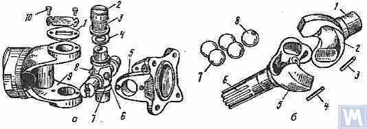
图 4.万向节:a - 万向节:1 - 盖;2 - 杯;3 - 滚针轴承;4 - 密封圈;5、9 - 轭;6 - 安全阀;7 - 十字架;8 - 黄油接头;10 - 螺钉;b - 等速万向节:1 - 内轴轴;2 - 驱动轭;3、4 - 螺柱;5 - 从动轭;6 - 外轴轴;7 - 滚珠;8 - 中心滚珠
2.万向节驱动装置故障
万向节驱动故障通常表现为车辆行驶时,特别是在换挡和发动机曲轴转速突然升高时(例如,从发动机制动过渡到加速时),万向节出现剧烈敲击声。万向节故障的一个迹象是温度升高(超过 100°C)。出现这种情况的原因是万向节的衬套和耳轴、滚针轴承、十字架和花键连接严重磨损,导致万向节不对中,滚针轴承承受巨大的冲击轴向载荷。万向节十字架软木密封件的损坏会导致耳轴及其轴承的快速磨损。
在维护过程中,用手双向急转传动轴,检查万向节驱动装置。轴的自由旋转程度决定了万向节和花键连接的磨损程度。每行驶 8,000 至 10,000 公里,检查变速箱从动轴法兰和主传动齿轮传动轴与端部万向节法兰的螺栓连接情况以及传动轴中间支架的紧固情况。还要检查花键连接处的橡胶套和万向节十字的软木密封件的状况。所有紧固螺栓必须完全拧紧(拧紧扭矩为 8-10 kgf-m)。
万向节的滚针轴承使用变速箱用液体润滑油润滑;大多数车辆的花键连接使用润滑脂(US-1、US-2、1-13 等)润滑;严禁使用润滑脂润滑滚针轴承。在某些车辆中,花键连接采用变速箱油润滑。安装在橡胶套筒中的中间支撑轴承实际上不需要润滑,因为在工厂装配时已经进行了润滑。ZIL-130 车辆的支撑轴承在定期维护时(每行驶 1100-1700 公里)通过压力接头加注润滑脂。
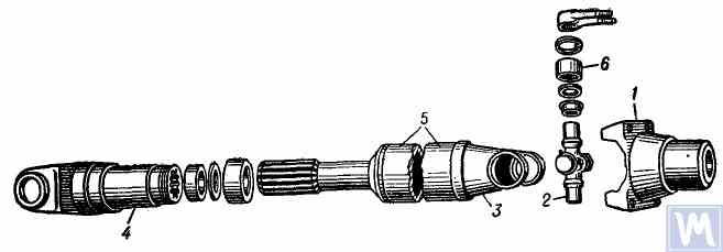
图 5.万向节传动装置:1 - 用于固定传动轴的法兰;2 - 万向节十字架;3 - 万向节轭;4 - 滑动轭;5 - 传动轴管;6 - 封闭端滚针轴承
万向节传动装置由两个带滚针轴承的万向节(通过空心轴连接)和一个带渐开线花键的滑动轭组成。为确保可靠的防污保护并为花键连接提供良好的润滑,与变速箱副轴 (2) 连接的滑动轭 (6) 被放置在变速箱壳体的延伸部分 (1) 中。此外,花键连接的这一位置(在接头之间的区域之外)大大提高了万向节传动装置的刚度,并降低了滑动花键连接磨损时轴振动的可能性。
驱动轴由薄壁电焊管(8)制成,两个相同的轭(9)分别压入管内,然后通过电弧焊焊接在一起。十字轴(25)的滚针轴承座(18)压入轭(9)的孔眼中,并用弹簧挡圈(20)固定。每个万向节轴承包含22个滚针(21)。冲压盖(24)压入十字轴突出的耳轴上,并在耳轴上安装软木圈(23)。轴承润滑使用角形黄油嘴(17),该黄油嘴拧入十字轴中心的螺纹孔中,并与十字轴耳轴中的通孔相连。万向节十字轴的另一侧,中心位置有一个安全阀(16),用于在填充十字轴和轴承时释放多余的润滑脂,并防止十字轴内部在运行过程中压力过大(当压力达到约 3.5 千克/平方厘米时,安全阀启动)。之所以需要安装安全阀,是因为十字轴内部压力过大会导致软木密封圈损坏(挤压)。
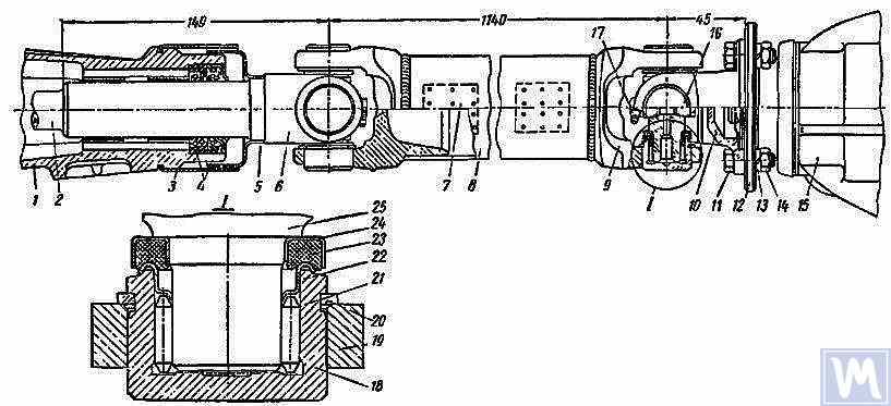
图 6.传动轴组件:1 - 变速箱延长件;2 - 变速箱副轴;3 和 5 - 挡土板;4 - 橡胶密封件;6 - 滑动轭;7 - 平衡板;8 - 传动轴管;9 - 轭;10 - 法兰轭;11 - 螺栓;12 - 后桥驱动齿轮法兰;13 - 弹簧垫圈;14 - 螺母;15 - 后轴;16 - 安全阀;17 - 角形润滑脂接头;18 - 滚针轴承;19 - 轭眼;20 - 弹簧固定环;21 - 滚针;22 - 带环形端头的垫圈;23 - 软木环;24 - 冲压盖;25 - 十字架
驱动轴由两个万向节组装而成,两端均需通过焊接平衡板(7)到驱动轴管上进行仔细的动态平衡。因此,拆卸驱动轴时,必须仔细标记所有零件,以便将其重新安装到原位。不遵守此说明会破坏驱动轴的平衡,从而引起振动,进而损坏变速箱和车身。如果单个零件磨损,尤其是驱动轴管因冲击而弯曲,导致组装后无法进行动态平衡,则必须更换整根驱动轴。
可能的传动轴故障、原因和解决方案
| 故障原因 | 解决方案 |
|---|---|
| 传动轴振动 | |
| 1.轴因障碍物而弯曲 | 1.调直装配好的轴并进行动态平衡,或更换装配好的轴 |
| 2.轴承和交叉磨损 | 2.更换轴承和十字架,并对装配好的轴进行动态平衡 |
| 3.加长衬套和滑动轭磨损 | 3.更换加长杆和滑动轭,并对装配好的轴进行动态平衡 |
| 启动和滑行时的敲击声 | |
| 1.滑动轭花键或二级齿轮箱轴磨损 | 1.更换磨损部件。更换滑动轭时,对装配好的轴进行动态平衡。 |
| 2.将法兰轭固定到后车桥驱动齿轮法兰上的螺栓松动 | 2.拧紧螺栓 |
| 万向节密封件甩油 | |
| 万向节密封件软木环的磨损 | 更换软木环,在重新组装过程中保持所有传动轴部件的相对位置。如果十字架和轴承有磨损,则更换轴承和十字架,并对组装好的轴进行动态平衡。 |
3.传动轴平衡
在修理和组装传动轴后,要在机器上对其进行动态平衡。图 7 显示了平衡机的一种设计。该机器由一个底板 (18)、一个安装在四根垂直弹性杆 (3) 上的摆架 (8) 组成,确保其在水平面内摆动。固定在支架 (4) 上的支架和前座 (9) 安装在摆架 (8) 的纵向管上。后头架 (6) 安装在活动横梁 (5) 上,可对不同长度的传动轴进行动态平衡。头架主轴安装在精密滚珠轴承上。前头架 (9) 的主轴由安装在机器底座上的电动机通过三角皮带驱动和中间轴驱动,中间轴上安装有一个刻度盘 (10)(刻度盘)。此外,在机器底板 (18) 上还安装了两个带有可伸缩锁定销 (17) 的支架 (15),以确保根据传动轴前端或后端的平衡情况固定摆架的前后端。
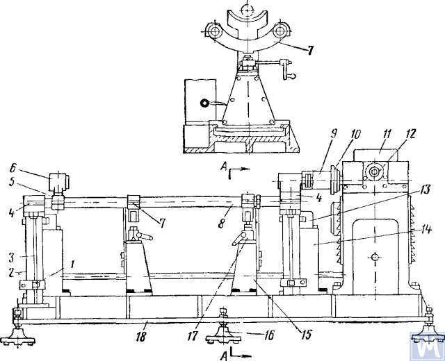
图 7.传动轴动平衡机
1-夹具;2-阻尼器;3-弹性杆;4-支架;5-可移动横梁;6-后头架;7-横杆;8-摆架;9-前驱动头架;10-刻度盘;11-毫伏计;12-换向器整流器轴刻度盘;13-磁电传感器;14-固定架;15-固定器架;16-支架;17-固定器;18-支撑板
固定支架 (14) 安装在机器板的后部,上面安装有磁电传感器 (13),连杆与摆杆框架的两端相连。为防止框架共振,在支架 (4) 下方安装了注满油的阻尼器 (2)。
在使用平衡机对驱动轴进行动平衡处理的过程中,需要先将带有滑动轭的驱动轴组件安装到机器上,并将其牢固地固定住。驱动轴的一端,是通过一个法兰轭连接到前部驱动主轴箱的法兰上的;而驱动轴的另一端,则是通过滑动轭的支撑颈,连接到后部主轴箱的花键套筒上的。接下来,需要检查驱动轴的旋转是否顺畅无阻,并使用固定器,将机器摆动架的一端固定住。启动机器之后,需要将整流器的刻度臂沿逆时针方向缓慢旋转,使毫伏表的指针达到其最大读数值。此时,毫伏表仪表上所显示出来的读数,对应的正是不平衡量的大小程度。毫伏表的刻度,是以克·厘米,或者以配重的克数来标定的。继续沿逆时针方向旋转整流器的刻度臂,使毫伏表的读数逐渐回落到零位,然后将机器停止运转。根据整流器刻度臂上所显示的读数,可以确定出角位移,也就是不平衡的位移角度;接着,通过用手转动驱动轴,将这一角度数值设置到中间轴的刻度臂上。平衡板的焊接位置,应当设在驱动轴的顶部,而配重的部分,则应设在校正平面的底部。随后,将平衡板安装到位,并在距离焊缝10毫米处,用一根细铁丝将其绑扎固定,再启动机器,检查装有平衡板之后驱动轴端的平衡情况。此处的不平衡量,不应超过70克·厘米,即700克·毫米。之后,松开摆动架的一端,同时用固定架,将摆动架的另一端固定住,再按照上文所述的同样工艺顺序,对驱动轴的另一端进行动平衡处理。
传动轴具有一些平衡特性。对于大多数零件来说,动平衡的基础是支撑颈(如电机转子、涡轮机、主轴、曲轴等),但对于传动轴来说,基础是法兰。在装配过程中,不同连接处不可避免地会出现间隙,从而导致不平衡。如果在平衡过程中无法达到最小的不平衡,轴就会被剔除。平衡精度受以下因素影响:
- 传动轴法兰着陆带与左右支撑头架夹紧法兰内孔之间的连接间隙;
- 法兰基面的径向和端面跳动;
- 铰链和花键连接处存在间隙。花键连接腔内如果存在润滑脂,则会导致“浮动”不平衡。如果这会影响达到所需的平衡精度,则驱动轴无需润滑脂即可进行平衡。
有些不平衡可能完全无法纠正。如果传动轴万向节的摩擦力增加,校正平面的相互影响也会增加。这会导致平衡性能和精度下降。
根据 OST 37.001.053-74,建立了以下不平衡标准:具有两个接头(双支撑)的传动轴需要动态平衡,具有三个接头(三支撑)的传动轴需要与中间支撑一起组装;在组装轴或联轴器之前,重量超过 5 公斤的传动轴和联轴器的法兰(轭)需要静态平衡;三关节传动轴两端或中间支撑处的传动轴残余不平衡标准通过特定的不平衡进行评估;
传动轴两端或中间支撑处的最大允许特定残余不平衡量标准,以及平衡台上任何位置的三节传动轴,均不得超过:乘用车、轻载卡车(1吨以下)和超小型客车的变速器不得超过6g-cm/kg,其余车辆不得超过10g-cm/kg。传动轴或三节传动轴的最大允许残余不平衡量标准,应在平衡台上以与最高车速下变速器中传动频率一致的转速进行测量。
说明:OST 37.001.053-74是1974年苏联汽车工业标准,此处仅作历史参考引用。以现代标准换算,3,000 rpm下6 g·cm/kg大致对应G 19,10 g·cm/kg大致对应G 31——该OST要求介于G 16和G 40之间,与ISO 21940-11(原ISO 1940-1)针对传动轴的等级要求是一致的。新的工作应按ISO 21940-11的等级来规定。
对于载重量为4吨及以上的卡车、小型和大型客车的传动轴和三节传动轴,允许将平衡台上的转速降低至最高车速下传动轴转速的70%。根据OST 37.001.053-74,传动轴的平衡转速应等于:
nb = (0.7 ... 1.0) nr,
其中 nb – 平衡旋转频率(应与机架的主要技术数据相对应,n=3000 min-1); nr – 最大工作旋转频率,分钟-1.
在实际应用中,由于接头和花键连接处存在间隙,驱动轴无法在建议的旋转频率下保持平衡。在这种情况下,可选择另一种旋转频率,并在该频率下实现平衡。
4.用于传动轴的现代平衡机
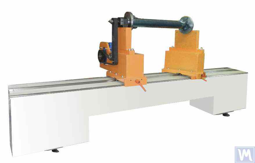
图 8.用于长达 2 米、重达 500 千克传动轴的平衡机
该模型有 2 个支架,可在 2 个校正平面上保持平衡。
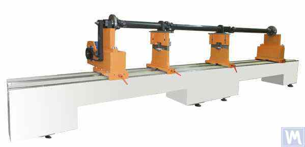
图 9.用于长达 4200 毫米、重达 400 千克传动轴的平衡机
该模型有 4 个支架,可同时在 4 个校正平面上进行平衡。
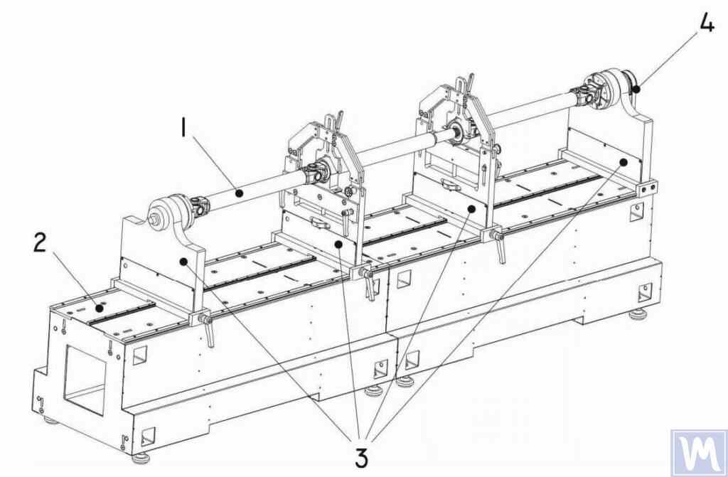
图 10.用于传动轴动平衡的卧式硬轴承平衡机
1 – 平衡对象(传动轴);2 – 机座;3 – 机器支座;4 – 机器驱动装置;机器支座的结构组成如图11所示。
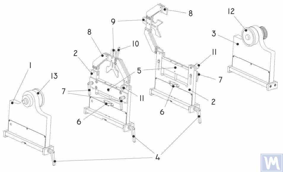
图 11.用于传动轴动平衡的机器支撑元件
1 - 左侧不可调支撑;2 - 中间可调支撑(2 件);3 - 右侧不可调固定支撑;4 - 支撑架锁定手柄;5 - 可移动支撑平台;6 - 支撑垂直调节螺母;7 - 垂直位置锁定手柄;8 - 支撑夹紧支架;9 - 中间轴承活动夹钳;10 - 夹钳锁定手柄;11 - 夹紧支架锁定;12 - 用于物品安装的驱动(前导)主轴;13 - 驱动主轴
5.传动轴平衡的准备工作
下面,我们将讨论机器支架的设置以及在机器支架上安装平衡部件(四支撑传动轴)的问题。
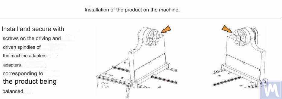
图 12.在平衡机主轴上安装过渡法兰
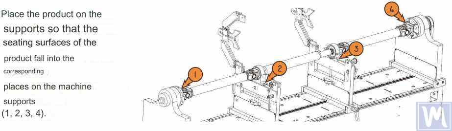
图 13.在平衡机支架上安装传动轴
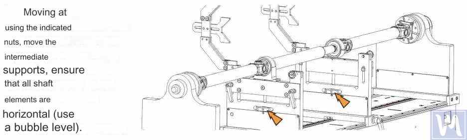
图 14.使用气泡水平仪水平校准平衡机支架上的传动轴
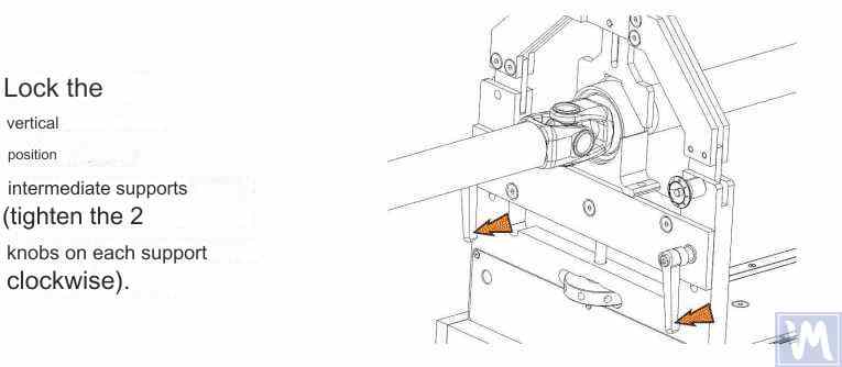
图 15.固定平衡机的中间支架以防止传动轴垂直位移
手动旋转物品一圈。确保旋转自如,不会卡在支架上。之后,机器的机械部分安装完毕,物品安装也就完成了。
6. 如何平衡传动轴:分步操作指南
我需要哪款套件? 一台在两个平面内进行校正的双支承机器(图8),需要用到双通道的Balanset-1A。而一台同时在四个平面内进行校正的四支承机器(图9,以及下文所述的操作步骤),则需要用到四通道的Balanset-4A。测量与计算的整个工作流程,两者是完全相同的;唯一不同的,只是通道的数量。下面所描述的操作步骤,是针对四平面的配置来说明的,而软件的截图,展示的则是双平面Balanset-1A上完全相同的工作流程——在Balanset-4A上,同样的这些界面,只是简单地增加了平面3和平面4而已。
下面以Balanset-4A测量系统为例,介绍在平衡机上进行传动轴平衡的过程。Balanset-4A是一款便携式平衡套件,可对在自身轴承中旋转或安装在平衡机上的转子进行一至四个校正平面的平衡。该设备最多包含四个振动传感器、一个相位角传感器、一个四通道测量单元,以及一台便携式计算机。
整个平衡过程,包括对校正配重的大小以及安装位置这些信息的测量、处理与显示,全部都是自动完成的,用户完全不需要具备说明书之外的任何额外技能或者专业知识。所有平衡作业所得到的结果,都会被保存在平衡档案(Balancing Archive)当中,如果有需要的话,还可以把它们打印成报告。除了平衡这项功能之外,Balanset-4A还可以当作一台普通的振动转速计来使用,能够在四个通道上,分别测量总振动的均方根值(RMS)、振动旋转分量的均方根值,并且对转子的旋转频率进行监控。
此外,该设备还可显示时间函数图和按振动速度绘制的振动频谱图,有助于评估平衡机械的技术状况。
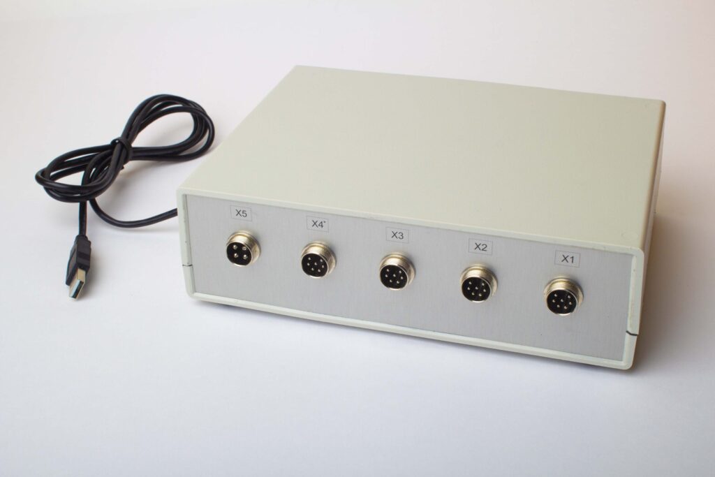
图16. 用作传动轴平衡机测量与运算系统的Balanset-4A设备外观图
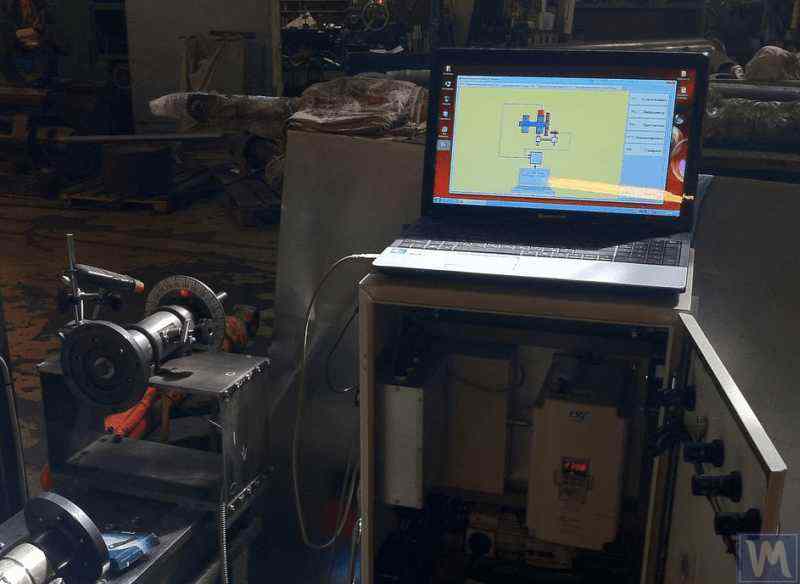
图17. 将Balanset-4A装置用作传动轴平衡机测量计算系统的示例
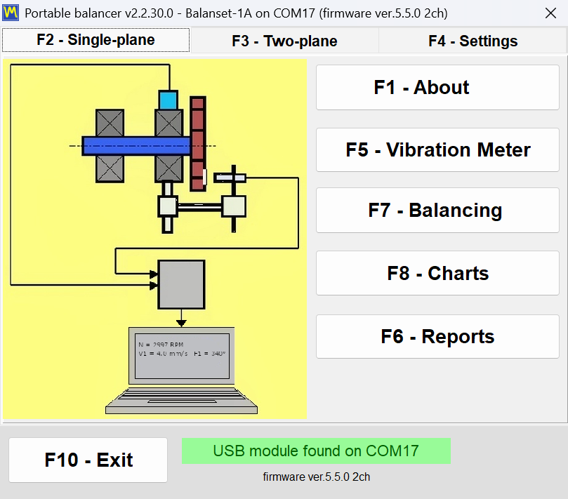
图 18。Balanset 软件主窗口:F1 - About、F5 - Vibration Meter、F6 - Balancing、F7 - Charts、F8 - Reports
Balanset-4A设备随附振动传感器。传感器为加速度计式;软件对信号进行积分处理,并以mm/s RMS的形式显示振动速度。
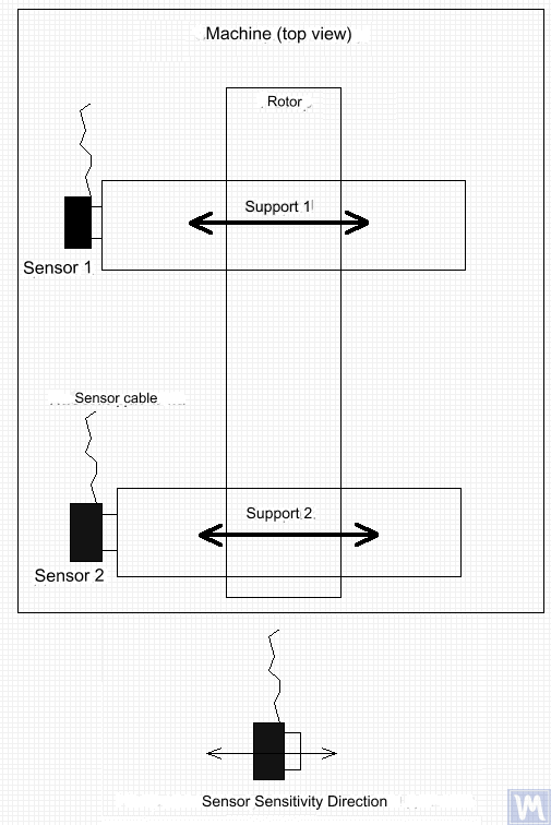
图19. 将Balanset-4A振动传感器安装在平衡机支座上
传感器灵敏轴的方向应与支座的振动位移方向一致,在本例中即为水平方向。有关传感器安装的更多信息,请参见 运行状态下的转子平衡.
- 在平衡机支架上安装振动传感器 1、2、3、4。
- 将振动传感器连接至连接器 X1、X2、X3 和 X4。
- 安装相位角传感器(激光转速计)5,使平衡转子的径向(或端面)与传感器外壳之间的标称间隙在 10 至 300 毫米之间。
- 在转子表面贴上宽度至少为 10-15 毫米的反光胶带标记。
- 将相角传感器连接至连接器 X5。
- 将测量装置连接到计算机的 USB 端口。
- 使用市电时,请将计算机连接至电源装置。
- 将供电装置连接至 220 伏 50 赫兹的网络。
- 打开电脑,启动Balanset软件。
- 通过 “F6 - Balancing” 按钮打开平衡工作区,并在 “Plane count” 字段中设置所需的校正平面数,这样连接到测量单元输入端的振动传感器即可同时测量振动。
- 计算机屏幕上会显示传感器与测量单元连接方式的示意图,如图18所示。
在进行平衡之前,建议使用测振仪模式(F5 按钮)进行测量。
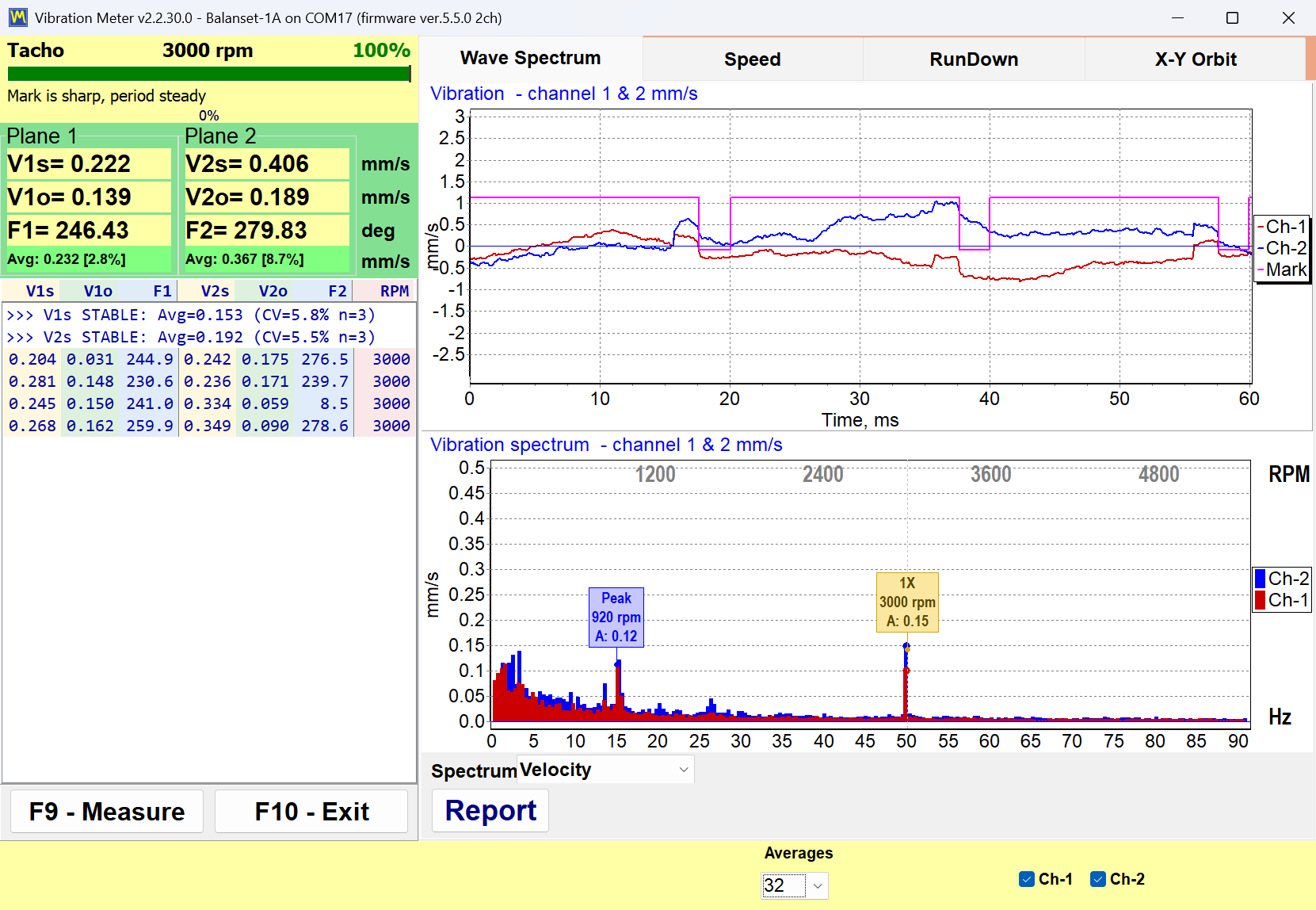
图20. 振动计模式(F5):总振动V1s、V2s及转动分量V1o、V2o,附相位F1、F2,以mm/s RMS的振动速度显示
如果总振动幅值 V1s (V2s) 与旋转分量幅值 V1o (V2o) 大致匹配,则可以推断机构振动的主要贡献来自转子不平衡。如果总振动幅值 V1s (V2s) 明显超过旋转分量 V1o (V2o),建议检查机构——检查轴承状况,确保其牢固地安装在基础上,确认转子在旋转过程中不会接触固定部件,并考虑其他机构振动的影响等。
在图表模式(“F7 - Charts”,“F5-Spectrum (Hz)” 选项卡)中研究时间函数图和振动频谱,在此可能会有帮助。
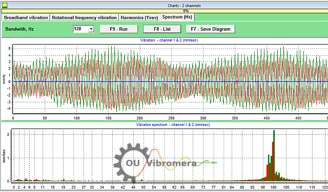
图 21.振动时间函数和频谱图
该图显示了振动水平最高的频率。如果这些频率与平衡机构转子的旋转频率不同,则需要在平衡之前确定这些振动成分的来源并采取措施消除它们。
解读传动轴频谱:1x为不平衡,2x可能来自万向节本身。 转频(1×)处的主导峰值指向不平衡——这正是平衡所要消除的。转频二倍频(2×)处的主导峰值,尤其是伴有较强轴向振动时,则指向万向节夹角、十字轴或花键磨损,或 错位:以角度 γ 工作的万向节会使从动叉每转超前和滞后两次,因此即使轴已完全平衡,也会产生 2x 分量。平衡无法消除它——应使两个万向节的角度相等(γ1 = γ2),并先检查万向节。在图表模式(“F7 - Charts”)中,“F5-Spectrum (Hz)” 选项卡显示频谱,“F3-1x vibration” 选项卡显示转频分量;在 3000 min-1 1x = 50 Hz,2x = 100 Hz。
同样重要的是要注意测振仪模式下读数的稳定性--测量过程中振动幅度和相位的变化不应超过 10-15%。否则,机械装置可能会在共振区附近运行。在这种情况下,应调整转子速度。
在对新转子进行四平面平衡时,需要进行五次标定运转,以及至少一次修正运转(Run T)。第一次不加试重的机器运转,在平衡工作区中作为Run 0进行振动测量。随后的各次运转均加装试重,依次将试重安装在传动轴的每个校正平面上(即每个平衡机支承处)。
以后每次运行前,都应采取以下步骤:
- 停止平衡机器转子的旋转。
- 取下之前安装的试重。
- 在下一个平面安装试重。
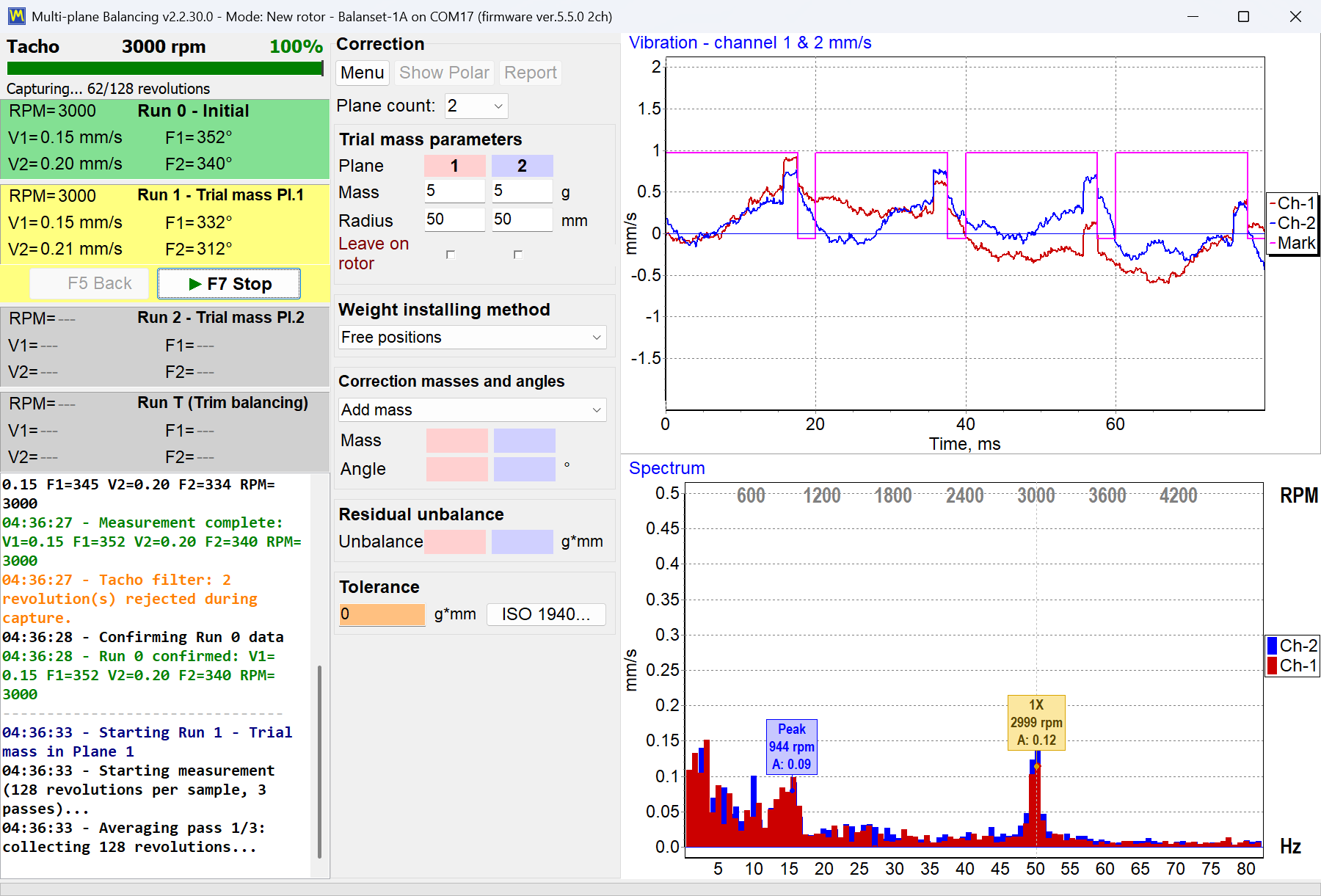
图 22。测量运行期间的平衡工作区(“F6 - Balancing”):Run 0 - 初始运行,试重运行 Run 1 和 Run 2,以及微调运行 Run T
每次测量完成后,转子旋转频率(Nob)以及有效值(Vo1, Vo2, Vo3, Vo4)和相位(F1, F2, F3, F4)都会保存在程序窗口相应的字段中,对应被平衡转子旋转频率下的振动值。完成第五次运转(Weight in Plane 4)后,会显示带有极坐标图的平衡结果(见图23),其中给出计算出的质量值(M1, M2, M3, M4)和安装角度(f1, f2, f3, f4) 的校正砝码,这些砝码需要安装在转子的四个平面上,以补偿转子的不平衡。
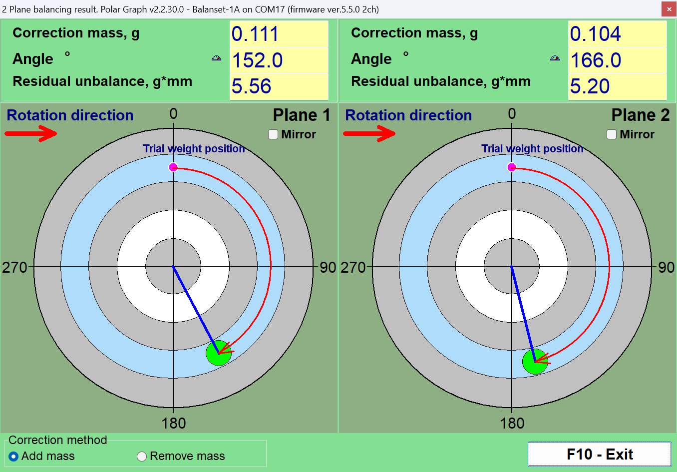
图23. 平衡结果的极坐标图:各平面计算出的校正质量和角度,自试重位置沿旋转方向测量得出
请注意! 在平衡机第五次运行期间完成测量过程后,必须停止转子旋转并移除之前安装的试配重块。只有在此之后,才能继续在转子上安装(或移除)校正配重块。
在极坐标系中,转子上添加(或移除)校正配重的角位置是从试配重安装位置测量的。角度测量方向与转子旋转方向一致。在按叶片平衡的情况下,平衡转子中条件上视为第一个叶片的叶片与试配重安装位置一致。计算机显示屏上显示的叶片编号方向与转子旋转方向一致。
在这个版本的程序中,默认假定校正重块是以增加质量的方式安装在转子上,这一点由“Add mass”(增加质量)字段中的标记体现。如果需要通过去除质量(例如钻孔)来校正不平衡,可用鼠标在“Remove mass”(去除质量)字段中设置标记,此后校正重块的角度位置会自动改变180度。
在平衡转子上安装校正配重后,进行精修运行(Run T)以检查平衡效果。精修运行完成后,转子转频(Nob)和有效值(Vo1, Vo2, Vo3, Vo4)和相位(F1, F2, F3, F4)平衡转子在其旋转频率处所测得的振动数值,将会被保存下来,记录在程序窗口当中对应的字段里面。与此同时,平衡结果(参见图23)也会随之更新,显示出需要在转子上安装(或者拆除)的附加校正配重的各项计算参数,以便用来补偿其残余不平衡量。除此之外,这个工作区界面,还会显示出经过平衡之后所达到的残余不平衡数值。如果这台被平衡转子的残余振动数值,以及/或者残余不平衡数值,符合技术文档当中所规定的公差要求,那么就可以完成整个平衡过程;反之,则可以继续进行平衡作业。这种方法,可以通过逐次逼近的方式,去修正在被平衡转子上安装(或者拆除)校正配重时,有可能出现的各种误差。
如果平衡过程继续进行,则需要根据平衡结果中显示的计算参数,在被平衡转子上继续安装(或拆除)校正配重。
根据五次标定运行结果计算出的转子平衡系数(动态影响系数)会保存在计算机内存中,在平衡同类型转子时可通过“Load Coefficients”(加载系数)功能重复使用。
7.推荐的刚性转子平衡精度等级
以下等级为ISO 1940-1的平衡品质等级G,其数值在被ISO 21940-11:2016取代后保持不变。该等级定义为G = eper·Ω,其中 eper 是许用比残余不平衡量(g·mm/kg = µm),Ω = 2πn/60是使用角速度(rad/s)。许用残余不平衡量由此得出,记为Uper = 9549·G·M/n [g·mm],在各校正平面之间分配。参见我们的 ISO 1940-1 词汇表条目。
公路车辆传动轴的默认等级为G 40;当图纸或主机厂规范提出特殊要求时,则采用G 16。请注意,残余不平衡和振动是两项独立的验收标准:整机装配后的振动应依据ISO 20816(原ISO 10816)进行评定——详见我们的 ISO 10816-1 词汇表条目。
G等级表仅适用于刚性转子——即工作转速保持在第一阶弯曲临界转速的约0.5~0.7倍以下的转子。较长的传动轴(2米及以上,以及任何带中间支撑的轴)可能接近这一极限:应同时对照工作转速和平衡转速检查轴的第一阶临界转速。如果轴在该转速下表现为柔性,应采用模态/多转速平衡程序(ISO 21940-12)——按刚性转子的两平面校正方法将不起作用。
表 2.推荐的刚性转子平衡精度等级。

| 机器类型(转子) | 平衡精度等级 | 平衡质量等级 G = eper·Ω, mm/s |
|---|---|---|
| 用于大型低速船用柴油机的驱动曲轴(结构不平衡)(活塞速度小于 9 米/秒) | G 4000 | 4000 |
| 用于大型低速船用柴油机的驱动曲轴(结构平衡)(活塞速度小于 9 米/秒) | G 1600 | 1600 |
| 安装在隔振器上的驱动曲轴(结构不平衡 | G 630 | 630 |
| 刚性支架上的驱动曲轴(结构不平衡 | G 250 | 250 |
| 为客车、卡车和机车组装的往复式发动机 | G 100 | 100 |
| 安装在隔振器上的驱动曲轴(结构平衡) | G 40 | 40 |
| 汽车车轮、轮辋、轮对、传动轴(万向轴) | G 40 | 40 |
| 农业机械 | G 16 | 16 |
| 刚性支架上的驱动曲轴(平衡的) | G 16 | 16 |
| 破碎机 | G 16 | 16 |
| 有特殊要求的传动轴(螺旋桨轴/万向轴) | G 16 | 16 |
| 飞机燃气轮机 | G 6.3 | 6.3 |
| 离心机(分离器、沉淀器) | G 6.3 | 6.3 |
| 电动机和发电机(轴高度至少为 80 毫米),最高额定转速可达 950 分钟-1 | G 6.3 | 6.3 |
| 轴高度小于 80 毫米的电机 | G 6.3 | 6.3 |
| 风机 | G 6.3 | 6.3 |
| 齿轮传动装置 | G 6.3 | 6.3 |
| 通用机械 | G 6.3 | 6.3 |
| 金属切割机 | G 6.3 | 6.3 |
| 造纸机 | G 6.3 | 6.3 |
| 水泵 | G 6.3 | 6.3 |
| 涡轮增压器 | G 6.3 | 6.3 |
| 水轮机 | G 6.3 | 6.3 |
| 压缩机 | G 6.3 | 6.3 |
| 计算机控制的驱动器 | G 2.5 | 2.5 |
| 最大额定转速超过 950 分钟的电动机和发电机(轴高度至少为 80 毫米)。-1 | G 2.5 | 2.5 |
| 燃气轮机和蒸汽轮机 | G 2.5 | 2.5 |
| 金属切割机驱动器 | G 2.5 | 2.5 |
| 纺织机械 | G 2.5 | 2.5 |
| 音频和视频设备驱动器 | G 1 | 1 |
| 磨床驱动装置 | G 1 | 1 |
| 高精密设备的主轴和驱动器 | G 0.4 | 0.4 |
关于驱动轴平衡的常见问题
什么是传动轴平衡?
驱动轴平衡是校正驱动轴中任何质量不平衡的过程,使其平稳旋转且不引起振动。这包括测量驱动轴一侧较重的位置,然后通过增加或减少少量重量(例如焊接平衡块)来抵消这种不平衡。平衡的驱动轴运转平稳,可防止车辆部件过度振动和磨损。
为什么传动轴平衡很重要?
不平衡的驱动轴会导致强烈的振动,尤其是在特定速度下,并且可能在加速或换挡时发出咔嗒声。随着时间的推移,这些振动会损坏轴承、万向节和其他传动系统部件。平衡驱动轴可以消除这些振动,确保更平稳的行驶,减少零件的负担,并避免代价高昂的损坏或停机。
传动轴不平衡的常见症状有哪些?
传动轴不平衡或故障的典型症状包括车辆地板或座椅明显振动或颤动,尤其是在车速增加时。换挡或加速减速时,您还可能会听到敲击声或咔哒声。在某些情况下,万向节可能会因不平衡而过热。如果您发现这些迹象,则很可能是传动轴需要平衡或维修。
如何平衡传动轴?
传动轴的平衡工作,通常是使用专门的平衡机来完成的。把传动轴装夹好,并使其高速旋转,与此同时,传感器负责检测其中是否存在不平衡。接下来,技术人员会根据机器所显示出来的读数,在特定的位置上,往传动轴上添加一些小的配重(或者去除一部分材料)。这一过程会不断重复,直到传动轴旋转起来不再产生明显的振动为止。像Balanset-4A这样的现代化系统,能够对整个过程加以引导,并且精确计算出,究竟应当在什么位置、添加多少重量,才能实现精准的平衡。
结论
总之,适当的传动轴平衡对于安全、性能和成本节约至关重要。 通过检测并纠正不平衡,可以避免零部件不必要的磨损,防止发生破坏性故障,并保持机器处于最佳性能状态。像我们的Balanset-1A和Balanset-4A这样的现代平衡系统,让这一过程变得高效,即使是小型维修车间也能达到专业水准的效果。
如果您遇到持续的传动轴振动问题,或需要可靠的平衡解决方案,请立即行动。请按照本指南中的步骤操作,或咨询我们的专家寻求帮助。采用正确的方法和设备,确保您的传动轴在未来数年内平稳可靠地运行。 联系我们 了解更多信息或探索最适合您需求的传动轴平衡设备。








Nikolai Shelkovenko
Nikolai Shelkovenko是一名振动分析工程师,也是Vibromera的创始人兼首席执行官。 15年多来,他一直在现场——而非在试验台上——为旋转设备进行平衡:粉碎机、工业风机、破碎机、离心机、轴和主轴。正是这些实际工作催生了Balanset系列仪器——它们被设计为一种专业人员可以随身携带到机器旁、在现场独立使用的工具,而非实验室设备。 Vibromera成立于2017年,自2023年起总部设于葡萄牙波尔图。Balanset系列产品的研发、组装与支持均在此完成。旗舰产品是Balanset-1A,一款用于单平面及双平面平衡和振动诊断的便携式分析仪。 Nikolai亲自参与客户支持工作,处理各种棘手的平衡案例,并参与软件开发。他以任何语言为全球客户提供服务。


0 评论