ড্রাইভ শ্যাফ্ট ব্যালান্সিং: বিস্তৃত নির্দেশিকা
নিজেই ড্রাইভশ্যাফট ব্যালান্স করুন — গাড়িতেই, খোলার দরকার নেই
Balanset-1A একটি দুই-প্লেন পোর্টেবল ব্যালান্সার: এক কিটে ভাইব্রেশন সেন্সর, লেজার টাকোমিটার এবং সফটওয়্যার। এটি গাড়িতে ড্রাইভশ্যাফট, এছাড়া ফ্যান, ফ্লাইহুইল, ক্রাশার এবং তাদের নিজস্ব বিয়ারিংয়ে অন্য যেকোনো রোটর ব্যালান্স করে। দুই বছরের ওয়ারেন্টি, বিশ্বব্যাপী DHL / UPS শিপিং, কোনো সাবস্ক্রিপশন নেই।
ভাবুন, আপনি একটি ট্রাক চালাচ্ছেন এবং হঠাৎ তীব্র কম্পন অনুভব করলেন বা ত্বরণ বা গিয়ার বদলের সময় জোরে ধাক্কার শব্দ শুনলেন। এটি শুধু বিরক্তিকর নয় — এটি ভারসাম্যহীন ড্রাইভশ্যাফ্টের লক্ষণ হতে পারে। প্রকৌশলী ও প্রযুক্তিবিদদের জন্য, এ ধরনের কম্পন ও শব্দ মানে হলো দক্ষতা হ্রাস, উপাদানে দ্রুত ক্ষয়, এবং সমস্যা উপেক্ষা করলে সম্ভাব্য ব্যয়বহুল ডাউনটাইম।
গাড়িতে কাজ করছেন? দেখুন খোলা ছাড়াই গাড়িতে ড্রাইভশ্যাফট ব্যালান্সিং.
গাড়িতে ড্রাইভশ্যাফট ব্যালান্সিং: একটি প্রকৃত কাজ, ধাপে ধাপে
নিচের ছবিগুলি একটি প্রকৃত ব্যালেন্সিং কাজ থেকে নেওয়া, যা লিফটে থাকা গাড়ির সাথে সম্পন্ন হয়েছিল। ড্রাইভশ্যাফট কখনো খোলা হয়নি: সেন্সরগুলি গাড়িতেই সংযুক্ত, শ্যাফটটি ড্রাইভট্রেনের মাধ্যমে ইঞ্জিন দ্বারা ঘোরানো হয়, এবং সংশোধন ওজন নিচ থেকে লাগানো হয়। এটি শ্যাফটটিকে তার নিজস্ব বিয়ারিং এবং নিজস্ব ওয়ার্কিং অ্যাঙ্গেলে রাখে, তাই ফলাফলটি প্রতিফলিত করে অ্যাসেম্বলিটি আসলে কীভাবে চলে — যা একটি বেঞ্চ ব্যালেন্সিং মেশিন সম্পূর্ণরূপে পুনরুৎপাদন করতে পারে না।
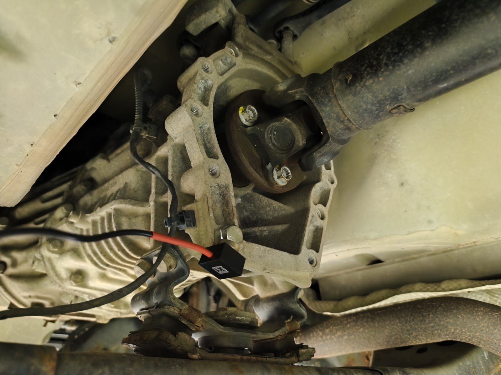
চিত্র 24। ড্রাইভশ্যাফট সাপোর্ট বিয়ারিং-এর যতটা সম্ভব কাছাকাছি, ফাইনাল ড্রাইভ হাউজিং-এ মাউন্ট করা vibration sensor।
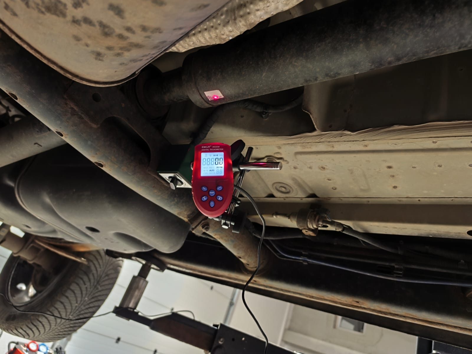
চিত্র 25। শ্যাফটের একটি reflective tape-এর স্ট্রিপে তাক করা Laser tachometer — এটি ঘূর্ণন গতি এবং unbalance-এর ফেজ কোণ উভয়ই সরবরাহ করে।
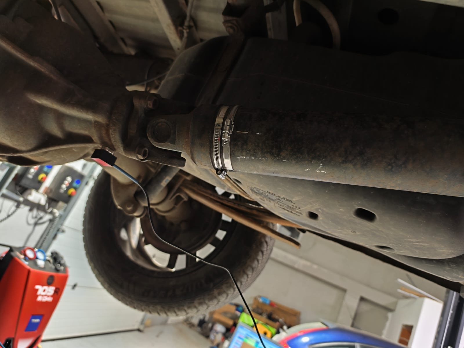
চিত্র 26। সফটওয়্যার দ্বারা গণনাকৃত কোণ ও ভরে স্টেইনলেস হোজ ক্ল্যাম্প দিয়ে শ্যাফট টিউবে সুরক্ষিত করা correction ওজন।
সম্পূর্ণ পদ্ধতি — সেন্সর স্থাপন, নিরাপদ টেস্ট রান, ট্রায়াল ওজন এবং residual-vibration চেক — বর্ণনা করা হয়েছে খোলা ছাড়াই গাড়িতে ড্রাইভশ্যাফট ব্যালান্সিং.
এই বিস্তৃত নির্দেশিকায় আমরা ড্রাইভশ্যাফ্ট ব্যালান্স সমস্যার ব্যবহারিক সমাধান দিচ্ছি। আপনি জানবেন ড্রাইভশ্যাফ্ট কী এবং কেন এর ব্যালান্সিং দরকার, কম্পন বা শব্দ সৃষ্টিকারী সাধারণ ত্রুটিগুলো চিনতে পারবেন, এবং ডাইনামিক ড্রাইভশ্যাফ্ট ব্যালান্সিংয়ের একটি পরিষ্কার ধাপে-ধাপে প্রক্রিয়া অনুসরণ করতে পারবেন। এই সর্বোত্তম পদ্ধতিগুলো প্রয়োগ করে আপনি মেরামতের খরচ বাঁচাতে, ত্রুটিসন্ধানের সময় কমাতে এবং আপনার যন্ত্রপাতি বা যানবাহনকে ন্যূনতম কম্পনে নির্ভরযোগ্যভাবে চালাতে পারবেন।
সূচিপত্র
- 1. ড্রাইভশ্যাফটের প্রকারভেদ
- 2. ইউনিভার্সাল জয়েন্ট ড্রাইভের ত্রুটি
- 3. ড্রাইভশ্যাফ্ট ব্যালেন্সিং
- 4. ড্রাইভশ্যাফ্টের জন্য আধুনিক ব্যালেন্সিং মেশিন
- 5. ড্রাইভশ্যাফ্ট ব্যালেন্সিংয়ের জন্য প্রস্তুতি
- 6. কীভাবে ড্রাইভশাফ্ট ব্যালেন্স করবেন: ধাপে ধাপে পদ্ধতি
- 7. অনমনীয় রটারগুলির জন্য ভারসাম্যপূর্ণ নির্ভুলতা ক্লাসের প্রস্তাবিত
1. ড্রাইভশ্যাফটের প্রকারভেদ
একটি সর্বজনীন জয়েন্ট ড্রাইভ (ড্রাইভশ্যাফ্ট) এমন একটি প্রক্রিয়া যা সার্বজনীন জয়েন্টের কেন্দ্রে ছেদ করা শ্যাফ্টের মধ্যে টর্ক প্রেরণ করে এবং একটি কোণে একে অপরের সাথে আপেক্ষিকভাবে চলতে পারে। একটি গাড়িতে, ক্লাসিক্যাল বা অল-হুইল-ড্রাইভ কনফিগারেশনের ক্ষেত্রে ড্রাইভশ্যাফ্ট গিয়ারবক্স (বা ট্রান্সফার কেস) থেকে চালিত এক্সেলগুলিতে টর্ক প্রেরণ করে। অল-হুইল-ড্রাইভ যানবাহনের জন্য, ইউনিভার্সাল জয়েন্ট সাধারণত গিয়ারবক্সের চালিত শ্যাফ্টকে ট্রান্সফার কেসের ড্রাইভ শ্যাফটের সাথে এবং ট্রান্সফার কেসের চালিত শ্যাফ্টকে চালিত এক্সেলের প্রধান ড্রাইভের ড্রাইভ শ্যাফটের সাথে সংযুক্ত করে।
Units mounted on the frame (such as the gearbox and transfer case) can move relative to each other due to the deformation of their supports and the frame itself. Meanwhile, the drive axles are attached to the frame through the suspension and can move relative to the frame and the units mounted on it due to the deformation of the suspension’s elastic elements. This movement can change not only the angles of the driveshafts connecting the units but also the distance between the units.
ইউনিভার্সাল জয়েন্ট ড্রাইভের একটি উল্লেখযোগ্য অসুবিধা রয়েছে: শ্যাফটের অসম ঘূর্ণন। যদি একটি শ্যাফট সমানভাবে ঘোরে, তবে অন্যটি ঘোরে না, এবং শ্যাফটগুলির মধ্যবর্তী কোণ বাড়ার সাথে সাথে এই অসমতা বৃদ্ধি পায়। এই সীমাবদ্ধতা অনেক প্রয়োগে ইউনিভার্সাল জয়েন্ট ড্রাইভ ব্যবহার প্রতিরোধ করে, যেমন সামনের চাকা-চালিত গাড়ির ট্রান্সমিশনে, যেখানে মূল সমস্যা হলো ঘূর্ণায়মান চাকায় টর্ক প্রেরণ করা। দুটি ইউনিভার্সাল জয়েন্ট একই শ্যাফটে ব্যবহার করে, সমান জয়েন্ট কোণে সেট করে (γ1 = γ2) এবং ইন্টারমিডিয়েট শ্যাফটের উভয় প্রান্তের ইয়োক একই তলে (ইন-ফেজ) রেখে এই অসুবিধা আংশিকভাবে পূরণ করা যায়। 90° ফেজ-ভিন্ন ইয়োক ওঠানামা বাতিল করে না — বরং তা বাড়িয়ে দেয়। তবে, সমান ঘূর্ণন প্রয়োজন এমন প্রয়োগে সাধারণত কনস্ট্যান্ট ভেলোসিটি জয়েন্ট (CV জয়েন্ট) ব্যবহার করা হয়। CV জয়েন্ট একই উদ্দেশ্য পূরণ করে এমন একটি আরও উন্নত কিন্তু আরও জটিল নকশা।
ইউনিভার্সাল জয়েন্ট ড্রাইভ ড্রাইভশ্যাফ্ট এবং মধ্যবর্তী সমর্থন দ্বারা সংযুক্ত এক বা একাধিক সর্বজনীন জয়েন্টগুলি নিয়ে গঠিত হতে পারে।
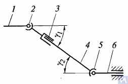
চিত্র 1. একটি সর্বজনীন জয়েন্ট ড্রাইভের চিত্র: 1, 4, 6 — ড্রাইভশ্যাফ্ট; 2, 5 — সর্বজনীন জয়েন্টগুলি; 3 - ক্ষতিপূরণ সংযোগ; u1, u2 — শ্যাফ্টের মধ্যে কোণ
In general, a universal joint drive consists of universal joints 2 and 5, driveshafts 1, 4, and 6, and a compensating connection 3. Sometimes the driveshaft is installed on an intermediate support attached to the vehicle frame cross member. Universal joints ensure the transmission of torque between shafts whose axes intersect at an angle. Universal joints are divided into non-uniform and constant velocity types. Non-uniform velocity joints are further classified into elastic and rigid types. Constant velocity joints can be ball-type with dividing grooves, ball-type with a dividing lever, and cam-type. They are typically installed in the drive of the leading controlled wheels, where the angle between the shafts can reach 45°, and the center of the universal joint must coincide with the intersection point of the wheel’s rotation axes and its turning axis.
ইলাস্টিক ইউনিভার্সাল জয়েন্ট সংযোগকারী উপাদানের ইলাস্টিক বিকৃতির কারণে 2...3° কোণে ছেদকারী অক্ষবিশিষ্ট শ্যাফটের মধ্যে টর্ক প্রেরণ করে। একটি দৃঢ় অসম-বেগ জয়েন্ট দৃঢ় অংশগুলির চলমান সংযোগের মাধ্যমে একটি শ্যাফট থেকে অন্যটিতে টর্ক প্রেরণ করে। এটি দুটি ইয়োক নিয়ে গঠিত – 3 এবং 5, যাদের সিলিন্ড্রিক্যাল গর্তে সংযোগকারী উপাদান – ক্রস 4-এর প্রান্ত A, B, C, এবং D বিয়ারিং-এর উপর ইনস্টল করা থাকে। ইয়োকগুলি শ্যাফট 1 এবং 2-এর সাথে দৃঢ়ভাবে সংযুক্ত। ইয়োক 5 ক্রসের অক্ষ B–D-এর চারপাশে ঘুরতে পারে এবং একই সাথে, ক্রসের সাথে, অক্ষ A–C-এর চারপাশে ঘুরতে পারে, যার ফলে তাদের মধ্যবর্তী পরিবর্তনশীল কোণ সহ একটি শ্যাফট থেকে অন্যটিতে ঘূর্ণন প্রেরণ সম্ভব হয়।
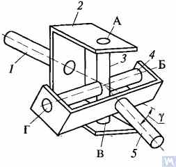
চিত্র 2. একটি অনমনীয় নন-ইউনিফর্ম বেগ সার্বজনীন জয়েন্টের চিত্র
যদি শ্যাফট 1 তার অক্ষের চারপাশে α কোণে ঘোরে, তাহলে শ্যাফট 2 একই সময়ের মধ্যে β কোণে ঘুরবে। শ্যাফট 1 এবং 2-এর ঘূর্ণন কোণের মধ্যে সম্পর্ক নিম্নলিখিত রাশি দ্বারা নির্ধারিত হয় tanα = tanβ * cosγ, যেখানে γ হলো সেই কোণ যেখানে শ্যাফটগুলির অক্ষ অবস্থিত। এই এক্সপ্রেশন নির্দেশ করে যে কোণ β কখনো কখনো কোণ α-এর চেয়ে কম, সমান, বা বেশি। এই কোণগুলির সমতা শ্যাফট 1-এর প্রতি 90° ঘূর্ণনে ঘটে। অতএব, শ্যাফট 1-এর সমান ঘূর্ণনের সাথে, শ্যাফট 2-এর কৌণিক বেগ অসম এবং সাইনুসয়ডাল নিয়ম অনুসারে পরিবর্তিত হয়। শ্যাফট অক্ষের মধ্যবর্তী কোণ γ বাড়ার সাথে সাথে শ্যাফট 2-এর ঘূর্ণনের অসমতা আরও উল্লেখযোগ্য হয়ে ওঠে।
যদি শ্যাফ্ট 2-এর অ-ইউনিফর্ম ঘূর্ণন ইউনিটগুলির শ্যাফ্টে প্রেরণ করা হয়, তাহলে ট্রান্সমিশনে অতিরিক্ত স্পন্দনশীল লোড ঘটবে, কোণ γ দিয়ে বৃদ্ধি পাবে। শ্যাফ্ট 2-এর নন-ইউনিফর্ম ঘূর্ণনকে ইউনিট শ্যাফ্টে প্রেরণ করা থেকে প্রতিরোধ করার জন্য, ইউনিভার্সাল জয়েন্ট ড্রাইভে দুটি সার্বজনীন জয়েন্ট ব্যবহার করা হয়। তারা ইনস্টল করা হয় যাতে কোণ γ1 এবং γ2 সমান হয়; সার্বজনীন জয়েন্টগুলির কাঁটাগুলি, অ-সমভাবে ঘূর্ণায়মান শ্যাফ্ট 4-এ স্থির, একই সমতলে অবস্থান করা উচিত।
The design of the main parts of universal joint drives is shown in Figure 3. A non-uniform velocity universal joint consists of two yokes (1) connected by a cross (3). One of the yokes sometimes has a flange, while the other is welded to the driveshaft tube or has a splined end (6) (or sleeve) for connection to the driveshaft. The trunnions of the cross are installed in the eyes of both yokes on needle bearings (7). Each bearing is housed in a case (2) and held in the yoke’s eye with a cap, which is attached to the yoke with two bolts locked by tabs on the washer. In some cases, the bearings are secured in the yokes with snap rings. To retain lubrication in the bearing and protect it from water and dirt, there is a rubber self-tightening seal. The inner cavity of the cross is filled with grease through a grease fitting, which reaches the bearings. The cross typically has a safety valve to protect the seal from damage due to the pressure of the grease being pumped into the cross. The splined connection (6) is lubricated using the grease fitting (5).
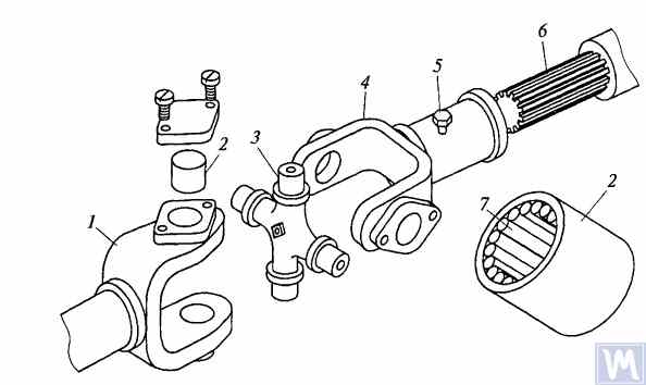
চিত্র 3. একটি অনমনীয় নন-ইনিফর্ম বেগ সার্বজনীন জয়েন্টের বিবরণ
দৃঢ় অসম-বেগ ইউনিভার্সাল জয়েন্ট দ্বারা সংযুক্ত শ্যাফটের অক্ষের মধ্যে সর্বোচ্চ কোণ সাধারণত 20°-এর বেশি হয় না, কারণ বড় কোণে কার্যকারিতা উল্লেখযোগ্যভাবে হ্রাস পায়। যদি শ্যাফট অক্ষের মধ্যে কোণ 0...2°-এর মধ্যে পরিবর্তিত হয়, তাহলে ক্রসের ট্রানিয়নগুলি নিডল বিয়ারিং দ্বারা বিকৃত হয়, যার ফলে ইউনিভার্সাল জয়েন্ট দ্রুত ব্যর্থ হয়।
In the transmissions of high-speed tracked vehicles, universal joints with gear coupling types, which allow the transmission of torque between shafts with axes intersecting at angles up to 1.5…2°, are often used.
ড্রাইভশ্যাফ্টগুলি সাধারণত টিউবুলার তৈরি করা হয়, বিশেষ ইস্পাত বিজোড় বা ঢালাই করা টিউব ব্যবহার করে। সার্বজনীন জয়েন্টগুলির জোয়াল, স্প্লিনড হাতা বা টিপগুলি টিউবগুলিতে ঝালাই করা হয়। ড্রাইভশ্যাফ্টের উপর কাজ করে ট্রান্সভার্স লোড কমাতে, সার্বজনীন জয়েন্টগুলিকে একত্রিত করে গতিশীল ভারসাম্য করা হয়। ভারসাম্যহীনতা ড্রাইভশ্যাফ্টে ব্যালেন্সিং প্লেট ঢালাই করে বা কখনও কখনও সার্বজনীন জয়েন্টের বিয়ারিং ক্যাপের নিচে ব্যালেন্সিং প্লেট বসানোর মাধ্যমে সংশোধন করা হয়। ফ্যাক্টরিতে সার্বজনীন জয়েন্ট ড্রাইভের সমাবেশ এবং ভারসাম্য বজায় রাখার পরে বিফ্যান সংযোগ অংশগুলির আপেক্ষিক অবস্থান সাধারণত বিশেষ লেবেল দ্বারা চিহ্নিত করা হয়।
সার্বজনীন জয়েন্ট ড্রাইভের ক্ষতিপূরণ সংযোগটি সাধারণত একটি স্প্লিনড সংযোগের আকারে তৈরি করা হয়, যা সর্বজনীন জয়েন্ট ড্রাইভ অংশগুলির অক্ষীয় চলাচলের অনুমতি দেয়। এটি একটি স্প্লিনড টিপ নিয়ে গঠিত যা ইউনিভার্সাল জয়েন্ট ড্রাইভের স্প্লিনড হাতাতে ফিট করে। তৈলাক্তকরণ একটি গ্রীস ফিটিংয়ের মাধ্যমে স্প্লিনড সংযোগে প্রবর্তন করা হয় বা সমাবেশের সময় প্রয়োগ করা হয় এবং গাড়ির দীর্ঘায়িত ব্যবহারের পরে প্রতিস্থাপিত হয়। একটি সীল এবং একটি কভার সাধারণত গ্রীস ফুটো এবং দূষণ প্রতিরোধ করার জন্য ইনস্টল করা হয়।
দীর্ঘ ড্রাইভশ্যাফ্টের জন্য, মধ্যবর্তী সমর্থনগুলি সাধারণত সর্বজনীন জয়েন্ট ড্রাইভে ব্যবহৃত হয়। একটি মধ্যবর্তী সাপোর্টে সাধারণত গাড়ির ফ্রেম ক্রস সদস্যের সাথে বোল্ট করা একটি বন্ধনী থাকে, যেখানে একটি রাবার ইলাস্টিক রিংয়ে একটি বল বিয়ারিং মাউন্ট করা হয়। বিয়ারিংটি ক্যাপ দিয়ে উভয় পাশে সিল করা হয়েছে এবং একটি তৈলাক্তকরণ ডিভাইস রয়েছে। স্থিতিস্থাপক রাবার রিং সমাবেশের ত্রুটি এবং ফ্রেমের বিকৃতির কারণে ঘটতে পারে এমন বিয়ারিং মিসলাইনমেন্টের জন্য ক্ষতিপূরণ দিতে সাহায্য করে।
সুই বিয়ারিং সহ একটি সর্বজনীন জয়েন্ট (চিত্র 4a) জোয়াল, একটি ক্রস, সুই বিয়ারিং এবং সীল নিয়ে গঠিত। সুই বিয়ারিং সহ কাপগুলি ক্রুশের ট্রুনিয়নগুলিতে লাগানো হয় এবং সিল দিয়ে সিল করা হয়। কাপগুলি স্ন্যাপ রিং বা স্ক্রু দিয়ে বেঁধে দেওয়া ক্যাপগুলির সাথে জোয়ালগুলিতে সুরক্ষিত থাকে। সার্বজনীন জয়েন্টগুলি ক্রসে অভ্যন্তরীণ ড্রিলিংয়ের মাধ্যমে গ্রীস ফিটিং এর মাধ্যমে লুব্রিকেট করা হয়। জয়েন্টে অতিরিক্ত তেলের চাপ দূর করতে একটি নিরাপত্তা ভালভ ব্যবহার করা হয়। ড্রাইভিং জোয়ালের অভিন্ন ঘূর্ণনের সময়, চালিত জোয়ালটি অ-অভিন্নভাবে ঘোরে: এটি প্রতি বিপ্লবে দুবার ড্রাইভিং জোয়াল থেকে এগিয়ে যায় এবং পিছিয়ে যায়। অ-ইউনিফর্ম ঘূর্ণন দূর করতে এবং জড় লোড কমাতে, দুটি সার্বজনীন জয়েন্ট ব্যবহার করা হয়।
সামনের ড্রাইভিং চাকার ড্রাইভে, ধ্রুবক বেগ সার্বজনীন জয়েন্টগুলি ইনস্টল করা হয়। GAZ-66 এবং ZIL-131 যানবাহনের ধ্রুবক বেগ জয়েন্ট ড্রাইভ 2, 5 (চিত্র 4b), চারটি বল 7, এবং একটি কেন্দ্রীয় বল 8 নিয়ে গঠিত। ড্রাইভিং জোয়াল 2 অভ্যন্তরীণ অ্যাক্সেল শ্যাফ্টের সাথে অবিচ্ছেদ্য, যখন চালিত জোয়ালটি নকল করা হয় যার সাথে শ্যাফটের বাইরের দিকের প্রান্তটি যুক্ত হয়। জোয়াল 2 থেকে জোয়াল 5 পর্যন্ত ড্রাইভিং মুহূর্তটি বল 7 এর মাধ্যমে প্রেরণ করা হয়, যা জোয়ালগুলিতে বৃত্তাকার খাঁজ বরাবর চলে। কেন্দ্রীয় বল 8 জোয়ালকে কেন্দ্র করে এবং 3, 4 স্টাড দ্বারা জায়গায় রাখা হয়। 2, 5 এর ঘূর্ণন ফ্রিকোয়েন্সি জোয়ালগুলির সাথে সম্পর্কিত প্রক্রিয়ার প্রতিসাম্যের কারণে একই। শ্যাফ্টের দৈর্ঘ্যের পরিবর্তন শ্যাফ্টের সাথে জোয়ালের মুক্ত বিফ্যান সংযোগ দ্বারা নিশ্চিত করা হয়।
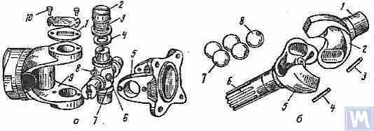
চিত্র 4. সার্বজনীন জয়েন্ট: a — সর্বজনীন জয়েন্ট: 1 — ক্যাপ; 2 - কাপ; 3 - সুই বহন; 4 - সীলমোহর; 5, 9 — জোয়াল; 6 - নিরাপত্তা ভালভ; 7 - ক্রস; 8 - গ্রীস ফিটিং; 10 - স্ক্রু; b — ধ্রুবক বেগ সার্বজনীন জয়েন্ট: 1 — অভ্যন্তরীণ এক্সেল শ্যাফ্ট; 2 - ড্রাইভিং জোয়াল; 3, 4 — স্টাড; 5 - চালিত জোয়াল; 6 - বাইরের এক্সেল শ্যাফ্ট; 7 - বল; 8 - কেন্দ্রীয় বল
2. ইউনিভার্সাল জয়েন্ট ড্রাইভের ত্রুটি
ইউনিভার্সাল জয়েন্ট ড্রাইভের ত্রুটিগুলি সাধারণত সার্বজনীন জয়েন্টগুলিতে তীক্ষ্ণ নক হিসাবে প্রকাশ পায় যা গাড়ি চলার সময় ঘটে, বিশেষ করে গিয়ারগুলির মধ্যে স্থানান্তরের সময় এবং ইঞ্জিন ক্র্যাঙ্কশ্যাফ্টের গতি হঠাৎ বৃদ্ধির সময় (উদাহরণস্বরূপ, ইঞ্জিন ব্রেকিং থেকে ত্বরণে রূপান্তরিত হওয়ার সময়)। সার্বজনীন জয়েন্টের ত্রুটির একটি চিহ্ন এটি একটি উচ্চ তাপমাত্রায় (100 ডিগ্রি সেলসিয়াস) গরম করা হতে পারে। ইউনিভার্সাল জয়েন্ট, সুই বিয়ারিং, ক্রস এবং স্প্লিনড কানেকশনের বুশিং এবং ট্রুনিয়নগুলির উল্লেখযোগ্য পরিধানের কারণে এটি ঘটে, যার ফলে সার্বজনীন জয়েন্টের মিসলাইনমেন্ট হয় এবং সুই বিয়ারিংগুলিতে উল্লেখযোগ্য প্রভাব অক্ষীয় লোড হয়। সার্বজনীন জয়েন্ট ক্রসের কর্ক সিলের ক্ষতির ফলে ট্রুনিয়ন এবং এর ভারবহন দ্রুত পরিধানের দিকে পরিচালিত করে।
রক্ষণাবেক্ষণের সময়, সার্বজনীন জয়েন্ট ড্রাইভটি উভয় দিকে হাত দিয়ে ড্রাইভশ্যাফ্টটিকে তীব্রভাবে ঘোরানোর মাধ্যমে পরীক্ষা করা হয়। শ্যাফ্টের মুক্ত ঘূর্ণনের ডিগ্রী সর্বজনীন জয়েন্ট এবং স্প্লিনড সংযোগগুলির পরিধান নির্ধারণ করে। প্রতি 8-10 হাজার কিলোমিটারে, গিয়ারবক্সের চালিত শ্যাফ্ট ফ্ল্যাঞ্জগুলির বোল্টযুক্ত সংযোগের অবস্থা এবং শেষ সার্বজনীন জয়েন্টগুলির ফ্ল্যাঞ্জগুলির সাথে প্রধান ট্রান্সমিশন গিয়ারের ড্রাইভ শ্যাফ্ট এবং ড্রাইভশ্যাফ্টের মধ্যবর্তী সমর্থনের বেঁধে রাখা অবস্থা পরীক্ষা করা হয়। বিফ্যান সংযোগগুলিতে রাবার বুটের অবস্থা এবং সর্বজনীন জয়েন্ট ক্রসের কর্ক সিলগুলিও পরীক্ষা করা হয়। সমস্ত বেঁধে রাখার বোল্ট অবশ্যই পুরোপুরি শক্ত করতে হবে (আঁটসাঁট টর্ক 8-10 kgf·m)।
সার্বজনীন জয়েন্টগুলির সুই বিয়ারিংগুলি ট্রান্সমিশন ইউনিটের জন্য ব্যবহৃত তরল তেল দিয়ে লুব্রিকেট করা হয়; বেশিরভাগ যানবাহনের স্প্লাইন্ড সংযোগগুলি গ্রীস দিয়ে লুব্রিকেট করা হয় (US-1, US-2, 1-13, ইত্যাদি); সুই বিয়ারিং তৈলাক্তকরণের জন্য গ্রীস ব্যবহার কঠোরভাবে নিষিদ্ধ। কিছু যানবাহনে, বিফ্যান সংযোগগুলি ট্রান্সমিশন তেল দিয়ে লুব্রিকেট করা হয়। মধ্যবর্তী সাপোর্ট বিয়ারিং, একটি রাবার হাতা মধ্যে মাউন্ট করা, কার্যত তৈলাক্তকরণের প্রয়োজন হয় না, কারণ এটি কারখানায় সমাবেশের সময় লুব্রিকেটেড হয়। ZIL-130 গাড়ির সাপোর্ট বিয়ারিং নিয়মিত রক্ষণাবেক্ষণের সময় (প্রতি 1100-1700 কিমি) চাপ ফিটিং এর মাধ্যমে গ্রীস দিয়ে লুব্রিকেট করা হয়।
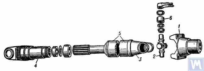
চিত্র 5. ইউনিভার্সাল জয়েন্ট ড্রাইভ: 1 — ড্রাইভশ্যাফ্ট সুরক্ষিত করার জন্য ফ্ল্যাঞ্জ; 2 - সার্বজনীন যৌথ ক্রস; 3 - সর্বজনীন যৌথ জোয়াল; 4 — স্লাইডিং জোয়াল; 5 - ড্রাইভশ্যাফ্ট টিউব; 6 — বন্ধ প্রান্ত সঙ্গে সুই রোলার ভারবহন
ইউনিভার্সাল জয়েন্ট ড্রাইভে সুই বিয়ারিং সহ দুটি সার্বজনীন জয়েন্ট থাকে, একটি ফাঁপা শ্যাফ্ট দ্বারা সংযুক্ত থাকে এবং একটি স্লাইডিং জোয়াল থাকে যার মধ্যে অনাবৃত স্প্লাইন থাকে। ময়লা থেকে নির্ভরযোগ্য সুরক্ষা নিশ্চিত করতে এবং স্প্লিনড সংযোগের ভাল তৈলাক্তকরণ প্রদান করতে, গিয়ারবক্সের সেকেন্ডারি শ্যাফ্ট (2) এর সাথে সংযুক্ত স্লাইডিং জোয়াল (6), গিয়ারবক্স হাউজিংয়ের সাথে সংযুক্ত একটি এক্সটেনশন (1) এ স্থাপন করা হয়। অতিরিক্তভাবে, স্প্লাইন্ড সংযোগের এই অবস্থান (জয়েন্টগুলির মধ্যে জোনের বাইরে) সার্বজনীন জয়েন্ট ড্রাইভের কঠোরতা উল্লেখযোগ্যভাবে বৃদ্ধি করে এবং স্লাইডিং স্প্লিনড সংযোগটি শেষ হয়ে গেলে শ্যাফ্ট কম্পনের সম্ভাবনা হ্রাস করে।
The driveshaft is made of a thin-walled electric-welded tube (8), into which two identical yokes (9) are press-fitted at each end and then welded by arc welding. Needle bearing housings (18) of the cross (25) are press-fitted into the eyes of the yokes (9) and are secured with spring retaining rings (20). Each universal joint bearing contains 22 needles (21). Stamped caps (24) are press-fitted onto the protruding trunnions of the crosses, into which cork rings (23) are installed. The bearings are lubricated using an angular grease fitting (17) screwed into a threaded hole in the center of the cross, connected to through channels in the cross’s trunnions. On the opposite side of the universal joint cross, a safety valve (16) is located in its center, designed to release excess grease when filling the cross and bearings, and to prevent pressure build-up inside the cross during operation (the valve activates at a pressure of about 3.5 kg/cm²). The necessity of including a safety valve is due to the fact that excessive pressure increase inside the cross can lead to damage (extrusion) of the cork seals.
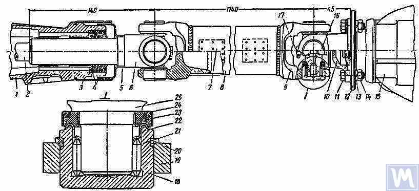
চিত্র 6. ড্রাইভশ্যাফ্ট সমাবেশ: 1 — গিয়ারবক্স এক্সটেনশন; 2 — গিয়ারবক্সের সেকেন্ডারি শ্যাফ্ট; 3 এবং 5 — ময়লা deflectors; 4 - রাবার সীল; 6 — স্লাইডিং জোয়াল; 7 - ব্যালেন্সিং প্লেট; 8 - ড্রাইভশ্যাফ্ট টিউব; 9 - জোয়াল; 10 - ফ্ল্যাঞ্জ জোয়াল; 11 - বল্টু; 12 — পিছনের এক্সেল ড্রাইভ গিয়ারের ফ্ল্যাঞ্জ; 13 - বসন্ত ধাবক; 14 - বাদাম; 15 - পিছনের এক্সেল; 16 - নিরাপত্তা ভালভ; 17 — কৌণিক গ্রীস ফিটিং; 18 - সুই বহন; 19 - জোয়াল চোখ; 20 - বসন্ত ধরে রাখার রিং; 21 - সুই; 22 — টরয়েডাল প্রান্ত সহ ওয়াশার; 23 - কর্ক রিং; 24 - স্ট্যাম্পড ক্যাপ; 25 — ক্রস
The driveshaft, assembled with both universal joints, is carefully dynamically balanced at both ends by welding balancing plates (7) to the tube. Therefore, when disassembling the shaft, all its parts must be carefully marked so that they can be reassembled in their original positions. Failure to follow this instruction disrupts the shaft’s balance, causing vibrations that can damage the transmission and vehicle body. If individual parts wear out, especially if the tube bends due to impact and it becomes impossible to dynamically balance the shaft after assembly, the entire shaft must be replaced.
ড্রাইভশ্যাফ্টের সম্ভাব্য ত্রুটি, তাদের কারণ এবং সমাধান
| ত্রুটির কারণ | Solution |
|---|---|
| ড্রাইভশ্যাফ্ট ভাইব্রেশন | |
| 1. একটি বাধা কারণে শ্যাফ্ট নমন | 1. একত্রিত শ্যাফ্টকে সোজা এবং গতিশীলভাবে ভারসাম্য দিন বা একত্রিত শ্যাফ্ট প্রতিস্থাপন করুন |
| 2. ভারবহন এবং ক্রস পরিধান | 2. বিয়ারিং এবং ক্রসগুলি প্রতিস্থাপন করুন এবং একত্রিত শ্যাফ্টকে গতিশীলভাবে ভারসাম্য দিন |
| 3. এক্সটেনশন বুশিং এবং স্লাইডিং জোয়ালের পরিধান | 3. এক্সটেনশন এবং স্লাইডিং জোয়াল প্রতিস্থাপন করুন এবং একত্রিত শ্যাফ্টকে গতিশীলভাবে ভারসাম্য বজায় রাখুন |
| শুরু এবং উপকূল যখন নক | |
| 1. স্লাইডিং জোয়াল স্প্লাইন বা সেকেন্ডারি গিয়ারবক্স শ্যাফ্টের পরিধান | 1. জীর্ণ অংশ প্রতিস্থাপন. স্লাইডিং জোয়াল প্রতিস্থাপন করার সময়, একত্রিত শ্যাফ্টকে গতিশীলভাবে ভারসাম্য বজায় রাখুন |
| 2. আলগা বোল্ট পিছনের এক্সেল ড্রাইভ গিয়ার ফ্ল্যাঞ্জে ফ্ল্যাঞ্জ জোয়ালকে সুরক্ষিত করে | 2. বোল্ট শক্ত করুন |
| ইউনিভার্সাল জয়েন্ট সীল থেকে তেল নিক্ষেপ | |
| সার্বজনীন যৌথ সীল মধ্যে কর্ক রিং পরিধান | কর্ক রিংগুলি প্রতিস্থাপন করুন, পুনরায় সংযুক্ত করার সময় সমস্ত ড্রাইভশ্যাফ্ট অংশগুলির আপেক্ষিক অবস্থান বজায় রাখুন। যদি ক্রস এবং বিয়ারিংগুলিতে পরিধান থাকে তবে বিয়ারিং এবং ক্রসগুলি প্রতিস্থাপন করুন এবং একত্রিত শ্যাফ্টকে গতিশীলভাবে ভারসাম্য দিন |
3. ড্রাইভশ্যাফ্ট ব্যালেন্সিং
ড্রাইভশ্যাফ্ট মেরামত এবং একত্রিত করার পরে, এটি একটি মেশিনে গতিশীলভাবে ভারসাম্যপূর্ণ। একটি ব্যালেন্সিং মেশিনের একটি ডিজাইন চিত্র 7 এ দেখানো হয়েছে। মেশিনটিতে একটি প্লেট (18), একটি পেন্ডুলাম ফ্রেম (8) চারটি উল্লম্ব ইলাস্টিক রড (3) এর উপর মাউন্ট করা হয়েছে, যা অনুভূমিক সমতলে এর দোলন নিশ্চিত করে। একটি বন্ধনী এবং সামনের হেডস্টক (9), একটি বন্ধনীতে সুরক্ষিত (4), পেন্ডুলাম ফ্রেমের অনুদৈর্ঘ্য টিউবগুলিতে মাউন্ট করা হয় (8)। পিছনের হেডস্টক (6) একটি চলমান ট্রাভার্সে (5), যা বিভিন্ন দৈর্ঘ্যের ড্রাইভশ্যাফ্টগুলির গতিশীল ভারসাম্যের অনুমতি দেয়। হেডস্টক স্পিন্ডলগুলি নির্ভুল বল বিয়ারিংগুলিতে মাউন্ট করা হয়। সামনের হেডস্টকের স্পিন্ডেল (9) মেশিনের বেসে ইনস্টল করা একটি বৈদ্যুতিক মোটর দ্বারা চালিত হয়, একটি V-বেল্ট ড্রাইভ এবং একটি মধ্যবর্তী শ্যাফ্টের মাধ্যমে, যার উপর একটি অঙ্গ (10) (গ্র্যাজুয়েটেড ডিস্ক) মাউন্ট করা হয়। অতিরিক্তভাবে, দুটি স্ট্যান্ড (15) প্রত্যাহারযোগ্য লকিং পিন (17) সহ মেশিন প্লেটে (18) ইনস্টল করা হয়েছে, যা ড্রাইভশ্যাফ্টের সামনের বা পিছনের প্রান্তের ভারসাম্যের উপর নির্ভর করে পেন্ডুলাম ফ্রেমের সামনের এবং পিছনের প্রান্তের স্থিরকরণ নিশ্চিত করে।
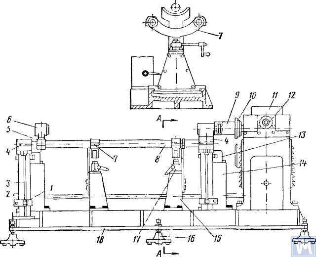
চিত্র 7. ড্রাইভশ্যাফ্টের জন্য গতিশীল ব্যালেন্সিং মেশিন
1-বাতা; 2 - ড্যাম্পার; 3-ইলাস্টিক রড; 4-বন্ধনী; 5-চলমান ট্রাভার্স; 6-পিছনের হেডস্টক; 7—ক্রসবার; 8-পেন্ডুলাম ফ্রেম; 9-সামনে ড্রাইভিং হেডস্টক; 10 - অঙ্গ-ডিস্ক; 11—মিলিভোল্টমিটার; 12 - কমিউটেটর-রেকটিফায়ার শ্যাফ্টের অঙ্গ; 13-ম্যাগনেটোইলেকট্রিক সেন্সর; 14-স্থির স্ট্যান্ড; 15-ফিক্সেটর স্ট্যান্ড; 16-সমর্থন; 17—ফিক্সেটর; 18-সাপোর্ট প্লেট
ফিক্সড স্ট্যান্ডগুলি (14) মেশিন প্লেটের পিছনে মাউন্ট করা হয় এবং তাদের উপর ম্যাগনেটোইলেকট্রিক সেন্সর (13) ইনস্টল করা হয়, রডগুলি পেন্ডুলাম ফ্রেমের প্রান্তের সাথে সংযুক্ত থাকে। ফ্রেমের অনুরণন কম্পন রোধ করতে, বন্ধনী (4) এর নীচে তেল দিয়ে ভরা ড্যাম্পার (2) ইনস্টল করা হয়।
ডাইনামিক ব্যালেন্সিং-এর সময় স্লাইডিং ইয়োক সহ ড্রাইভশ্যাফট অ্যাসেম্বলি মেশিনে ইনস্টল ও সুরক্ষিত করা হয়। ড্রাইভশ্যাফটের এক প্রান্ত ফ্ল্যাঞ্জ-ইয়োকের মাধ্যমে সামনের ড্রাইভিং হেডস্টকের ফ্ল্যাঞ্জের সাথে সংযুক্ত থাকে, এবং অন্য প্রান্ত স্লাইডিং ইয়োকের সাপোর্ট নেকের মাধ্যমে পিছনের হেডস্টকের স্প্লাইনড স্লিভের সাথে সংযুক্ত থাকে। এরপর ড্রাইভশ্যাফটের ঘূর্ণনের সহজতা পরীক্ষা করা হয়, এবং ফিক্সেটর ব্যবহার করে মেশিনের পেন্ডুলাম ফ্রেমের এক প্রান্ত স্থির করা হয়। মেশিন চালু করার পর, রেক্টিফায়ারের লিম্ব ঘড়ির কাঁটার বিপরীত দিকে ঘোরানো হয়, যাতে মিলিভোল্টমিটারের সূচক তার সর্বোচ্চ রিডিং-এ পৌঁছায়। মিলিভোল্টমিটারের রিডিং ভারসাম্যহীনতার মাত্রার সাথে সঙ্গতিপূর্ণ। মিলিভোল্টমিটারের স্কেল গ্রাম-সেন্টিমিটার বা কাউন্টারওয়েটের গ্রামে গ্র্যাজুয়েটেড। রেক্টিফায়ার লিম্ব ঘড়ির কাঁটার বিপরীত দিকে ঘোরানো অব্যাহত রেখে, মিলিভোল্টমিটারের রিডিং শূন্যে আনা হয়, এবং মেশিন বন্ধ করা হয়। রেক্টিফায়ার লিম্বের রিডিং-এর ভিত্তিতে কৌণিক সরণ (ভারসাম্যহীনতা সরণের কোণ) নির্ধারণ করা হয়, এবং ড্রাইভশ্যাফট হাতে ঘুরিয়ে এই মান ইন্টারমিডিয়েট শ্যাফট লিম্বে সেট করা হয়। ব্যালেন্সিং প্লেটের ওয়েল্ডিং স্থান ড্রাইভশ্যাফটের উপরে থাকবে, এবং ওজনযুক্ত অংশ সংশোধন তলে নিচে থাকবে। এরপর ব্যালেন্সিং প্লেট সংযুক্ত করে ওয়েল্ড থেকে 10 mm দূরত্বে পাতলা তার দিয়ে বাঁধা হয়, মেশিন চালু করা হয়, এবং প্লেটসহ ড্রাইভশ্যাফটের প্রান্তের ভারসাম্য পরীক্ষা করা হয়। ভারসাম্যহীনতা 70 g·cm (700 g·mm)-এর বেশি হওয়া উচিত নয়। এরপর, পেন্ডুলাম ফ্রেমের এক প্রান্ত মুক্ত করে এবং ফিক্সেটর স্ট্যান্ড দিয়ে অন্য প্রান্ত সুরক্ষিত করে, উপরে বর্ণিত প্রযুক্তিগত ক্রম অনুসারে ড্রাইভশ্যাফটের অন্য প্রান্তের ডাইনামিক ব্যালেন্সিং সম্পন্ন করা হয়।
ড্রাইভশ্যাফ্টের কিছু ভারসাম্যপূর্ণ বৈশিষ্ট্য রয়েছে। বেশিরভাগ অংশের জন্য, গতিশীল ভারসাম্যের জন্য ভিত্তি হল সাপোর্ট নেক (যেমন, বৈদ্যুতিক মোটরের রোটর, টারবাইন, স্পিন্ডেল, ক্র্যাঙ্কশ্যাফ্ট ইত্যাদি), কিন্তু ড্রাইভশ্যাফ্টের জন্য এটি হল ফ্ল্যাঞ্জ। সমাবেশের সময়, বিভিন্ন সংযোগে অনিবার্য ফাঁক থাকে যা ভারসাম্যহীনতার দিকে পরিচালিত করে। যদি ভারসাম্য বজায় রাখার সময় ন্যূনতম ভারসাম্যহীনতা অর্জন করা না যায় তবে শ্যাফ্টটি প্রত্যাখ্যান করা হয়। ভারসাম্যের নির্ভুলতা নিম্নলিখিত কারণগুলির দ্বারা প্রভাবিত হয়:
- ড্রাইভশ্যাফ্ট ফ্ল্যাঞ্জের ল্যান্ডিং বেল্ট এবং বাম এবং ডান সমর্থন হেডস্টকের ক্ল্যাম্পিং ফ্ল্যাঞ্জের ভিতরের গর্তের মধ্যে সংযোগের ফাঁক;
- ফ্ল্যাঞ্জের বেস পৃষ্ঠের রেডিয়াল এবং শেষ রানআউট;
- হিঞ্জ ও স্প্লাইনযুক্ত সংযোগে ফাঁক। স্প্লাইনযুক্ত সংযোগের গহ্বরে গ্রিজ থাকলে “ভাসমান” ভারসাম্যহীনতা দেখা দিতে পারে। এটি প্রয়োজনীয় ব্যালান্সিং নির্ভুলতা অর্জনে বাধা দিলে ড্রাইভশ্যাফট গ্রিজ ছাড়াই ব্যালান্স করা হয়।
কিছু ভারসাম্যহীনতা সম্পূর্ণরূপে অসংশোধনযোগ্য হতে পারে। যদি ড্রাইভশ্যাফ্টের সার্বজনীন জয়েন্টগুলিতে বর্ধিত ঘর্ষণ পরিলক্ষিত হয় তবে সংশোধন প্লেনের পারস্পরিক প্রভাব বৃদ্ধি পায়। এটি ভারসাম্যের কার্যক্ষমতা এবং নির্ভুলতা হ্রাসের দিকে পরিচালিত করে।
OST 37.001.053-74 অনুসারে ভারসাম্যহীনতার নিম্নলিখিত মানদণ্ড নির্ধারিত: দুটি জয়েন্টযুক্ত (দুই-অবলম্বন) ড্রাইভশ্যাফট ডায়নামিকভাবে ব্যালান্স করা হয়, আর তিনটি জয়েন্টযুক্ত (তিন-অবলম্বন) ড্রাইভশ্যাফট মধ্যবর্তী অবলম্বনসহ একত্রিত অবস্থায় ব্যালান্স করা হয়; 5 kg-এর বেশি ওজনের ড্রাইভশ্যাফট ও কাপলিংয়ের ফ্ল্যাঞ্জ (ইয়োক) শ্যাফট বা কাপলিং একত্রিত করার আগে স্ট্যাটিকভাবে ব্যালান্স করা হয়; প্রতিটি প্রান্তে বা তিন-জয়েন্ট ড্রাইভশ্যাফটের মধ্যবর্তী অবলম্বনে অবশিষ্ট ভারসাম্যহীনতার মানদণ্ড আপেক্ষিক (স্পেসিফিক) ভারসাম্যহীনতা দ্বারা মূল্যায়ন করা হয়;
শ্যাফটের প্রতিটি প্রান্তে বা মধ্যবর্তী অবলম্বনে, এবং তিন-জয়েন্ট ড্রাইভশ্যাফটের ক্ষেত্রে ব্যালান্সিং স্ট্যান্ডের যেকোনো অবস্থানে, সর্বোচ্চ অনুমোদিত আপেক্ষিক অবশিষ্ট ভারসাম্যহীনতার মান নিম্নের বেশি হওয়া উচিত নয়: যাত্রীবাহী গাড়ি, ছোট-লোডের ট্রাক (1 t পর্যন্ত) এবং খুব ছোট বাসের ট্রান্সমিশনের জন্য – 6 g-cm/kg, বাকিদের জন্য – 10 g-cm/kg। ড্রাইভশ্যাফট বা তিন-জয়েন্ট ড্রাইভশ্যাফটের সর্বোচ্চ অনুমোদিত অবশিষ্ট ভারসাম্যহীনতার মান ব্যালান্সিং স্ট্যান্ডে এমন ঘূর্ণন কম্পাঙ্কে নিশ্চিত করতে হবে, যা গাড়ির সর্বোচ্চ গতিতে ট্রান্সমিশনে তাদের কম্পাঙ্কের সমান।
লক্ষণীয়: OST 37.001.053-74 হলো 1974 সালের একটি সোভিয়েত অটোমোটিভ-শিল্প স্ট্যান্ডার্ড এবং এখানে ঐতিহাসিক রেফারেন্স হিসেবে উদ্ধৃত করা হয়েছে। আধুনিক পরিভাষায়, 3,000 rpm-এ 6 g·cm/kg প্রায় G 19-এর সাথে এবং 10 g·cm/kg প্রায় G 31-এর সাথে সঙ্গতিপূর্ণ — OST প্রয়োজনীয়তা G 16 এবং G 40-এর মধ্যে বসে, যা ড্রাইভ শ্যাফটের জন্য ISO 21940-11 (পূর্বে ISO 1940-1) গ্রেডের সাথে সামঞ্জস্যপূর্ণ। নতুন কাজে ISO 21940-11 গ্রেড নির্দিষ্ট করুন।
For driveshafts and three-joint driveshafts of trucks with a load capacity of 4 t and above, small and large buses, a reduction in the rotation frequency on the balancing stand to 70% of the transmission shafts’ rotation frequency at the maximum vehicle speed is allowed. According to OST 37.001.053-74, the balancing rotation frequency of driveshafts should be equal to:
nb = (0.7 ... 1.0) nr,
যেখানে nb – ব্যালান্সিংয়ের ঘূর্ণন কম্পাঙ্ক (স্ট্যান্ডের প্রধান প্রযুক্তিগত তথ্যের সাথে সামঞ্জস্যপূর্ণ হওয়া উচিত, n=3000 min-1); nr – সর্বাধিক কার্যকরী ঘূর্ণন ফ্রিকোয়েন্সি, min-1.
অনুশীলনে, জয়েন্ট এবং স্প্লিনড সংযোগের ফাঁকের কারণে, ড্রাইভশ্যাফ্ট প্রস্তাবিত ঘূর্ণন ফ্রিকোয়েন্সিতে ভারসাম্য বজায় রাখতে পারে না। এই ক্ষেত্রে, আরেকটি ঘূর্ণন ফ্রিকোয়েন্সি বেছে নেওয়া হয়, যেখানে এটি ভারসাম্য বজায় রাখে।
4. ড্রাইভশ্যাফ্টের জন্য আধুনিক ব্যালেন্সিং মেশিন
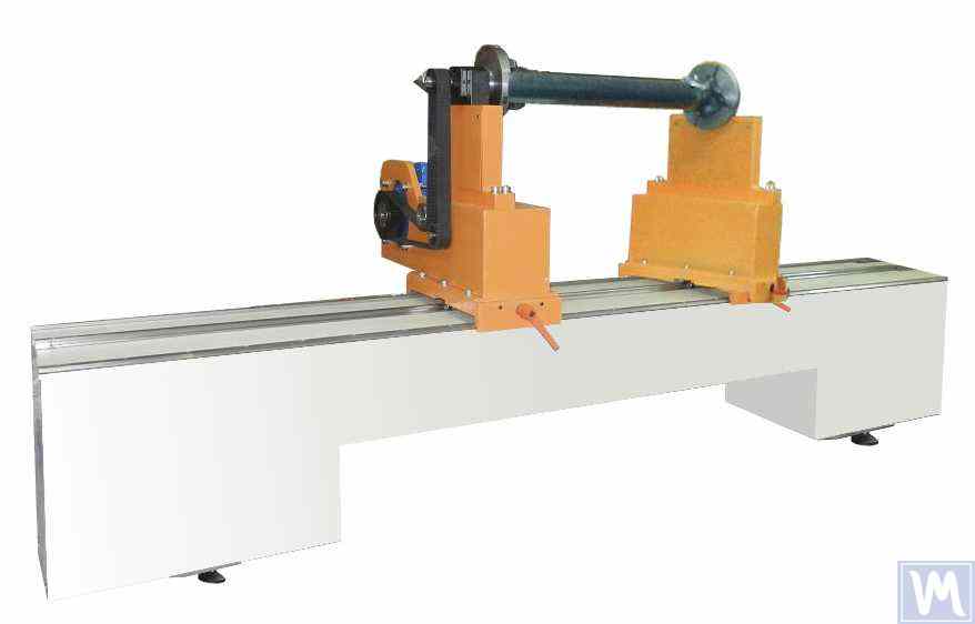
চিত্র 8. 2 মিটার পর্যন্ত লম্বা, 500 কেজি পর্যন্ত ওজনের ড্রাইভশ্যাফ্টের জন্য ব্যালেন্সিং মেশিন
মডেলটিতে 2টি স্ট্যান্ড রয়েছে এবং এটি 2টি সংশোধন প্লেনে ভারসাম্য বজায় রাখার অনুমতি দেয়।
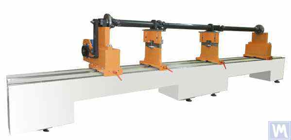
চিত্র 9. 4200 মিমি পর্যন্ত লম্বা, 400 কেজি পর্যন্ত ওজনের ড্রাইভশ্যাফ্টের জন্য ব্যালেন্সিং মেশিন
মডেলটিতে 4টি স্ট্যান্ড রয়েছে এবং এটি একই সাথে 4টি সংশোধন প্লেনে ভারসাম্য বজায় রাখার অনুমতি দেয়।
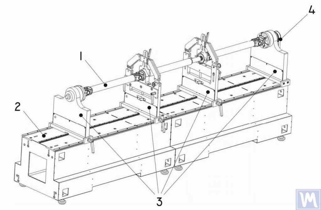
চিত্র 10. ড্রাইভশ্যাফ্টগুলির গতিশীল ভারসাম্যের জন্য অনুভূমিক হার্ড বিয়ারিং ব্যালেন্সিং মেশিন
1 – ব্যালান্সিং আইটেম (ড্রাইভশ্যাফট); 2 – মেশিন বেস; 3 – মেশিন সাপোর্ট; 4 – মেশিন ড্রাইভ; মেশিন সাপোর্টের কাঠামোগত উপাদানগুলো চিত্র 11-এ দেখানো হয়েছে।
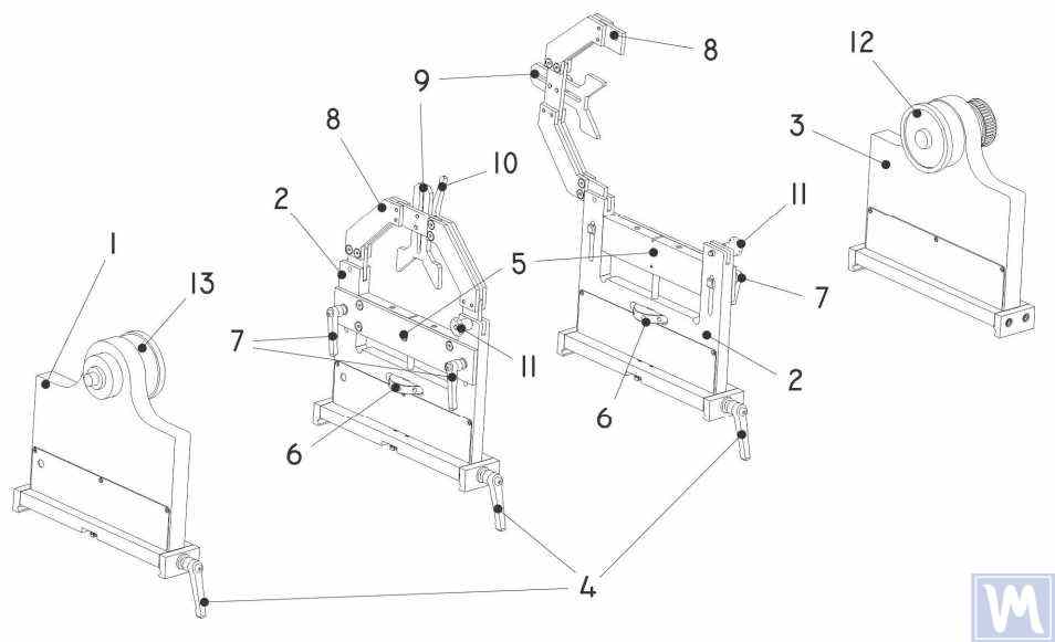
চিত্র 11. ড্রাইভশ্যাফ্টের গতিশীল ভারসাম্যের জন্য মেশিন সমর্থন উপাদান
1 – বাম অ-নিয়ন্ত্রিত সমর্থন; 2 – মধ্যবর্তী সামঞ্জস্যযোগ্য সমর্থন (2 পিসি।); 3 - ডান অ-নিয়ন্ত্রিত স্থায়ী সমর্থন; 4 - সমর্থন ফ্রেম লক হ্যান্ডেল; 5 - চলমান সমর্থন প্ল্যাটফর্ম; 6 – উল্লম্ব সমন্বয় বাদাম সমর্থন; 7 - উল্লম্ব অবস্থান লক হ্যান্ডলগুলি; 8 – ক্ল্যাম্পিং বন্ধনী সমর্থন; 9 – অন্তর্বর্তী ভারবহন চলমান বাতা; 10 – ক্ল্যাম্প লক হ্যান্ডেল; 11 – ক্ল্যাম্পিং বন্ধনী লক; 12 – আইটেম ইনস্টলেশনের জন্য ড্রাইভ (নেতৃস্থানীয়) টাকু; 13 - চালিত টাকু
5. ড্রাইভশ্যাফ্ট ব্যালেন্সিংয়ের জন্য প্রস্তুতি
নীচে, আমরা মেশিন সমর্থনের সেটআপ এবং মেশিন সমর্থনে ব্যালেন্সিং আইটেম (ফোর-সাপোর্ট ড্রাইভশ্যাফ্ট) ইনস্টল করার বিষয়টি বিবেচনা করব।
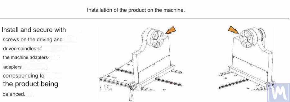
চিত্র 12. ব্যালেন্সিং মেশিনের স্পিন্ডলে ট্রানজিশনাল ফ্ল্যাঞ্জের ইনস্টলেশন
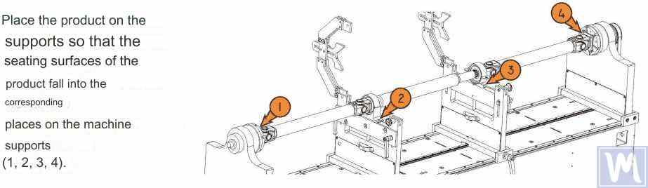
চিত্র 13. ব্যালেন্সিং মেশিনের সমর্থনে ড্রাইভশ্যাফ্ট ইনস্টল করা
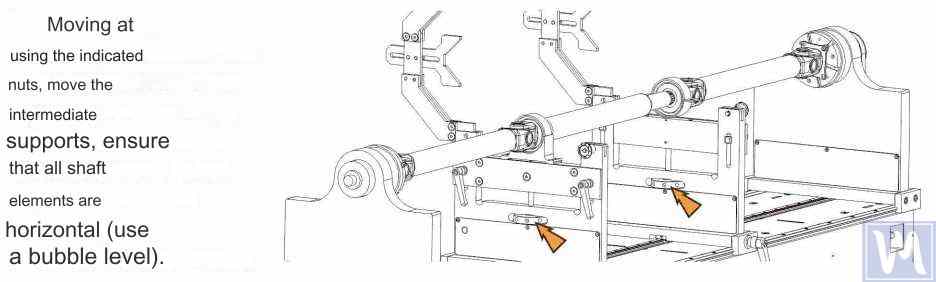
চিত্র 14. একটি বুদ্বুদ স্তর ব্যবহার করে ব্যালেন্সিং মেশিনের সমর্থনে ড্রাইভশ্যাফ্টকে অনুভূমিকভাবে সমতল করা
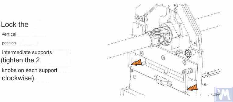
চিত্র 15. ড্রাইভশ্যাফ্টের উল্লম্ব স্থানচ্যুতি রোধ করতে ব্যালেন্সিং মেশিনের মধ্যবর্তী সমর্থনগুলি ঠিক করা
সম্পূর্ণ মোড়ের জন্য আইটেমটিকে ম্যানুয়ালি ঘোরান। নিশ্চিত করুন যে এটি অবাধে ঘোরে এবং সমর্থনগুলিতে জ্যাম না করে। এর পরে, মেশিনের যান্ত্রিক অংশ সেট আপ করা হয়, এবং আইটেম ইনস্টলেশন সম্পূর্ণ হয়।
6. কীভাবে ড্রাইভশাফ্ট ব্যালেন্স করবেন: ধাপে ধাপে পদ্ধতি
আমার কোন কিট প্রয়োজন? দুই তলে সংশোধনকারী দুই-সাপোর্ট মেশিনের (চিত্র ৮) জন্য দুই-চ্যানেল Balanset-1A প্রয়োজন। একই সাথে চার তলে সংশোধনকারী চার-সাপোর্ট মেশিনের (চিত্র ৯, এবং নিচের প্রক্রিয়া) জন্য চার-চ্যানেল Balanset-4A প্রয়োজন। পরিমাপ ও গণনার কর্মপ্রবাহ অভিন্ন; শুধুমাত্র চ্যানেল সংখ্যা ভিন্ন। নিচের প্রক্রিয়া একটি চার-তল সেটআপের জন্য বর্ণিত, যদিও সফটওয়্যার স্ক্রিনশটে দুই-তল Balanset-1A-তে একই কর্মপ্রবাহ দেখানো হয়েছে — Balanset-4A-তে একই স্ক্রিন শুধুমাত্র তল 3 এবং 4 যোগ করে।
ব্যালেন্সিং মেশিনে ড্রাইভশ্যাফট ব্যালেন্সিংয়ের প্রক্রিয়া Balanset-4A পরিমাপ সিস্টেম উদাহরণ হিসেবে ব্যবহার করে বিবেচনা করা হবে। Balanset-4A হলো একটি পোর্টেবল ব্যালেন্সিং কিট যা রোটরের এক, দুই, তিন, এবং চার সংশোধন তলে ব্যালেন্সিংয়ের জন্য ডিজাইন করা, হয় নিজস্ব বিয়ারিং-এ ঘূর্ণায়মান অথবা একটি ব্যালেন্সিং মেশিনে মাউন্ট করা। ডিভাইসটিতে চারটি পর্যন্ত কম্পন সেন্সর, একটি ফেজ অ্যাঙ্গেল সেন্সর, একটি চার-চ্যানেল পরিমাপ ইউনিট, এবং একটি পোর্টেবল কম্পিউটার অন্তর্ভুক্ত।
সংশোধনকারী ওজনের মাত্রা ও অবস্থান সম্পর্কিত তথ্যের পরিমাপ, প্রক্রিয়াকরণ এবং প্রদর্শনসহ সম্পূর্ণ ব্যালেন্সিং প্রক্রিয়া স্বয়ংক্রিয়ভাবে সম্পন্ন হয় এবং প্রদত্ত নির্দেশাবলীর বাইরে ব্যবহারকারীর অতিরিক্ত দক্ষতা ও জ্ঞানের প্রয়োজন হয় না। সমস্ত ব্যালেন্সিং অপারেশনের ফলাফল Balancing Archive-এ সংরক্ষিত হয় এবং প্রয়োজনে রিপোর্ট হিসেবে প্রিন্ট করা যায়। ব্যালেন্সিং ছাড়াও, Balanset-4A একটি নিয়মিত ভাইব্রো-টেকোমিটার হিসেবেও ব্যবহার করা যেতে পারে, যা চারটি চ্যানেলে মোট কম্পনের রুট মিন স্কয়ার (RMS) মান, কম্পনের ঘূর্ণন কম্পোনেন্টের RMS, এবং রোটর ঘূর্ণন ফ্রিকোয়েন্সি নিয়ন্ত্রণের পরিমাপের সুযোগ দেয়।
তদ্ব্যতীত, ডিভাইসটি কম্পন বেগের দ্বারা সময়ের ফাংশন এবং কম্পন বর্ণালীর গ্রাফ প্রদর্শনের অনুমতি দেয়, যা সুষম মেশিনের প্রযুক্তিগত অবস্থার মূল্যায়নে কার্যকর হতে পারে।
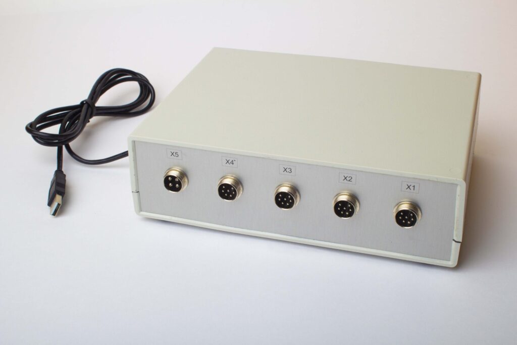
চিত্র 16। ড্রাইভশ্যাফট ব্যালান্সিং মেশিনের একটি পরিমাপ ও কম্পিউটিং সিস্টেম হিসেবে ব্যবহারের জন্য Balanset-4A ডিভাইসের বাহ্যিক দৃশ্য
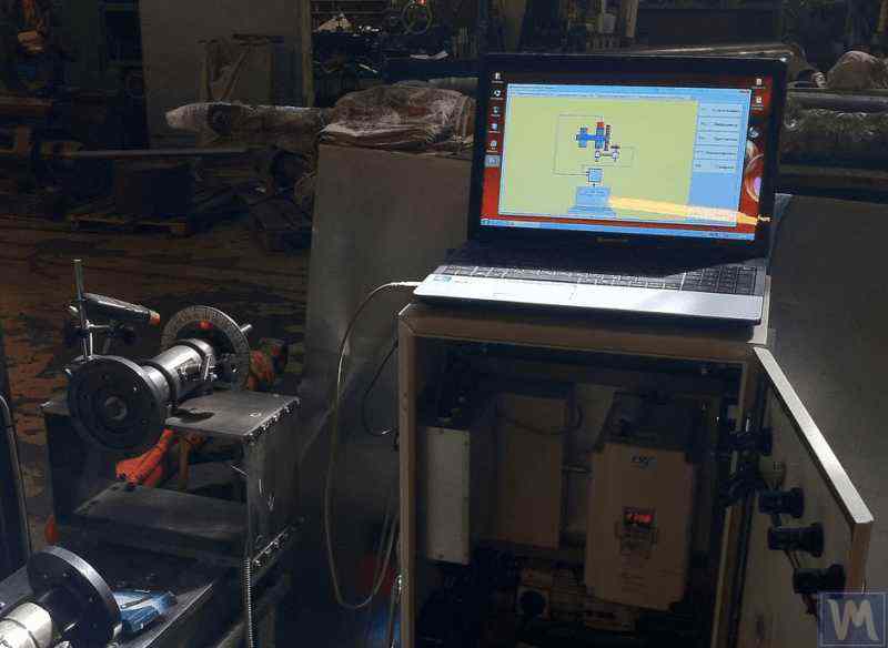
চিত্র 17। ড্রাইভশ্যাফট ব্যালান্সিং মেশিনের একটি পরিমাপ ও কম্পিউটিং সিস্টেম হিসেবে Balanset-4A ডিভাইস ব্যবহারের উদাহরণ
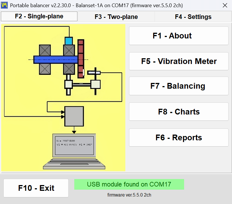
Figure 18. Balanset সফটওয়্যারের মূল উইন্ডো: F1 - About, F5 - Vibration Meter, F6 - Balancing, F7 - Charts, F8 - Reports
Balanset-4A ডিভাইসটি কম্পন সেন্সরসহ সরবরাহ করা হয়। সেন্সরগুলো accelerometer-ভিত্তিক; সফটওয়্যার তাদের সিগনাল ইন্টিগ্রেট করে এবং mm/s RMS-এ vibration velocity প্রদর্শন করে।
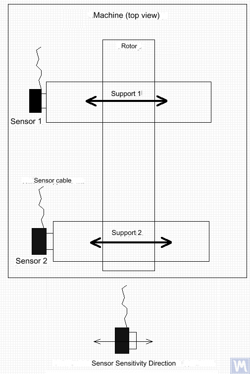
চিত্র 19। ব্যালান্সিং মেশিনের সাপোর্টে Balanset-4A কম্পন সেন্সরের ইনস্টলেশন
সেন্সরগুলির সংবেদনশীলতা অক্ষের দিক সাপোর্টের কম্পন স্থানচ্যুতির দিকের সাথে মিলে যাওয়া উচিত, এক্ষেত্রে – অনুভূমিক। সেন্সর ইনস্টলেশন সম্পর্কে অতিরিক্ত তথ্যের জন্য, দেখুন অপারেটিং কন্ডিশনে রোটর ব্যালান্সিং.
- ব্যালেন্সিং মেশিনের সমর্থনে ভাইব্রেশন সেন্সর 1, 2, 3, 4 ইনস্টল করুন।
- কানেক্টর X1, X2, X3, X4 এর সাথে ভাইব্রেশন সেন্সর সংযুক্ত করুন।
- ফেজ অ্যাঙ্গেল সেন্সর (লেজার টেকোমিটার) 5 ইনস্টল করুন যাতে সুষম রটারের রেডিয়াল (বা শেষ) পৃষ্ঠ এবং সেন্সর হাউজিংয়ের মধ্যে নামমাত্র ব্যবধান 10 থেকে 300 মিমি পর্যন্ত হয়।
- রটার পৃষ্ঠে কমপক্ষে 10-15 মিমি প্রস্থ সহ একটি প্রতিফলিত টেপ চিহ্ন সংযুক্ত করুন।
- ফেজ এঙ্গেল সেন্সরটিকে সংযোগকারী X5 এর সাথে সংযুক্ত করুন।
- কম্পিউটারের USB পোর্টে পরিমাপ ইউনিট সংযুক্ত করুন।
- মেইন পাওয়ার ব্যবহার করার সময়, কম্পিউটারটিকে পাওয়ার সাপ্লাই ইউনিটের সাথে সংযুক্ত করুন।
- পাওয়ার সাপ্লাই ইউনিটকে একটি 220 V, 50 Hz নেটওয়ার্কে সংযুক্ত করুন।
- কম্পিউটার চালু করুন এবং Balanset সফটওয়্যার শুরু করুন।
- “F6 - Balancing” বোতাম দিয়ে ব্যালান্সিং ওয়ার্কস্পেস খুলুন এবং “Plane count” ফিল্ডে প্রয়োজনীয় সংশোধন তলের সংখ্যা সেট করুন, যাতে পরিমাপ ইউনিটের ইনপুটে সংযুক্ত কম্পন সেন্সরগুলো একযোগে কম্পন পরিমাপ করে।
- সেন্সর এবং measuring unit-এর সংযোগ চিত্রিত করে এমন একটি mnemonic ডায়াগ্রাম কম্পিউটার ডিসপ্লেতে দেখা যায়, যেমনটি চিত্র 18-এ দেখানো হয়েছে।
ভারসাম্য সম্পাদন করার আগে, ভাইব্রোমিটার মোডে (F5 বোতাম) পরিমাপ করার পরামর্শ দেওয়া হয়।
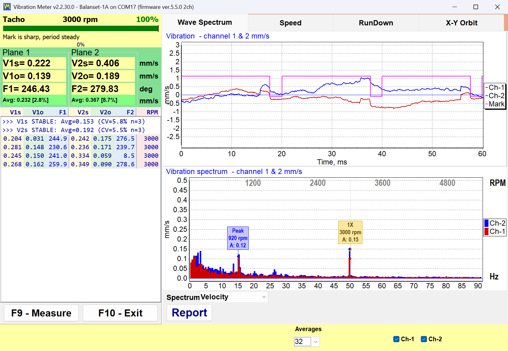
চিত্র 20। Vibration Meter মোড (F5): মোট কম্পন V1s, V2s এবং ঘূর্ণন উপাদান V1o, V2o ফেজ F1, F2-সহ, mm/s RMS-এ vibration velocity হিসেবে প্রদর্শিত
If the total vibration magnitude V1s (V2s) approximately matches the rotational component magnitude V1o (V2o), it can be assumed that the main contribution to the mechanism’s vibration is due to rotor imbalance. If the total vibration magnitude V1s (V2s) significantly exceeds the rotational component V1o (V2o), it is recommended to inspect the mechanism – check the condition of the bearings, ensure secure mounting on the foundation, verify that the rotor does not contact stationary parts during rotation, and consider the influence of vibrations from other mechanisms, etc.
চার্ট মোডে (“F7 - Charts”, “F5-Spectrum (Hz)” ট্যাব) সময়-ফাংশন গ্রাফ ও কম্পন স্পেকট্রাম অধ্যয়ন এখানে কাজে লাগতে পারে।
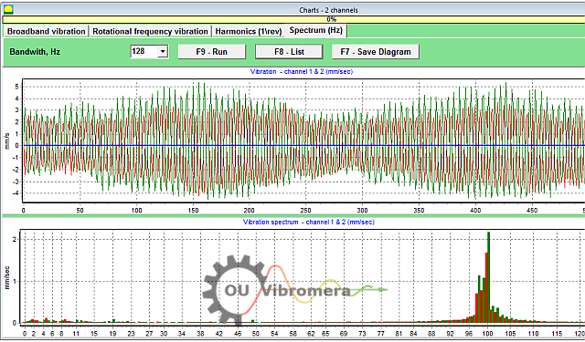
চিত্র 21. ভাইব্রেশন টাইম ফাংশন এবং স্পেকট্রাম গ্রাফ
The graph shows at which frequencies the vibration levels are highest. If these frequencies differ from the rotational frequency of the balanced mechanism’s rotor, it is necessary to identify the sources of these vibration components and take measures to eliminate them before balancing.
ড্রাইভশ্যাফটের স্পেকট্রাম পড়া: 1x হলো ভারসাম্যহীনতা, 2x জয়েন্ট নিজেই হতে পারে। ঘূর্ণন ফ্রিকোয়েন্সিতে (1x) একটি প্রধান পিক আনব্যালেন্স নির্দেশ করে — এটিই ব্যালান্সিং অপসারণ করে। ঘূর্ণন ফ্রিকোয়েন্সির দ্বিগুণে (2x) একটি প্রধান পিক, বিশেষ করে শক্তিশালী অক্ষীয় কম্পনের সাথে, জয়েন্ট অ্যাঙ্গেল, ক্ষয়প্রাপ্ত ক্রস বা স্প্লাইন, অথবা মিসঅ্যালাইনমেন্ট: γ কোণে কর্মরত একটি ইউনিভার্সাল (কার্ডান) জয়েন্ট চালিত ফর্কটিকে প্রতি আবর্তনে দুবার এগিয়ে ও পিছিয়ে দেয়, তাই শ্যাফট নিখুঁতভাবে ব্যালান্সড হলেও এটি 2x উপাদান তৈরি করে। ব্যালান্সিং এটি দূর করবে না — জয়েন্টের কোণগুলো সমান করুন (γ1 = γ2) এবং আগে জয়েন্টগুলো পরীক্ষা করুন। চার্ট মোডে (“F7 - Charts”) “F5-Spectrum (Hz)” ট্যাব স্পেকট্রাম এবং “F3-1x vibration” ট্যাব ঘূর্ণন উপাদান দেখায়; 3000 min-1 1x = 50 Hz এবং 2x = 100 Hz।
ভাইব্রোমিটার মোডে রিডিংয়ের স্থায়িত্বের দিকে মনোযোগ দেওয়াও গুরুত্বপূর্ণ - পরিমাপের সময় কম্পনের প্রশস্ততা এবং ফেজ 10-15% এর বেশি পরিবর্তন করা উচিত নয়। অন্যথায়, প্রক্রিয়াটি একটি অনুরণন অঞ্চলের কাছাকাছি কাজ করতে পারে। এই ক্ষেত্রে, রটার গতি সামঞ্জস্য করা উচিত।
একটি নতুন রোটরের চার-তল ব্যালেন্সিং সম্পন্ন করার সময়, পাঁচটি ক্যালিব্রেশন রান এবং ব্যালেন্স করা মেশিনের অন্তত একটি ট্রিম রান (Run T) প্রয়োজন। ট্রায়াল ওজন ছাড়া প্রথম মেশিন রানের সময় কম্পন পরিমাপ ব্যালেন্সিং ওয়ার্কস্পেসে Run 0 হিসেবে সম্পন্ন হয়। পরবর্তী রানগুলি একটি ট্রায়াল ওজন সহ সম্পন্ন হয়, যা প্রতিটি সংশোধন তলে (প্রতিটি ব্যালেন্সিং মেশিন সাপোর্টের এলাকায়) ক্রমানুসারে ড্রাইভশ্যাফটে ইনস্টল করা হয়।
প্রতিটি পরবর্তী রানের আগে, নিম্নলিখিত পদক্ষেপগুলি গ্রহণ করা উচিত:
- ব্যালান্স করা মেশিনের রোটরের ঘূর্ণন বন্ধ করুন।
- পূর্বে ইনস্টল করা পরীক্ষামূলক ওজন সরান.
- পরবর্তী প্লেনে পরীক্ষামূলক ওজন ইনস্টল করুন।
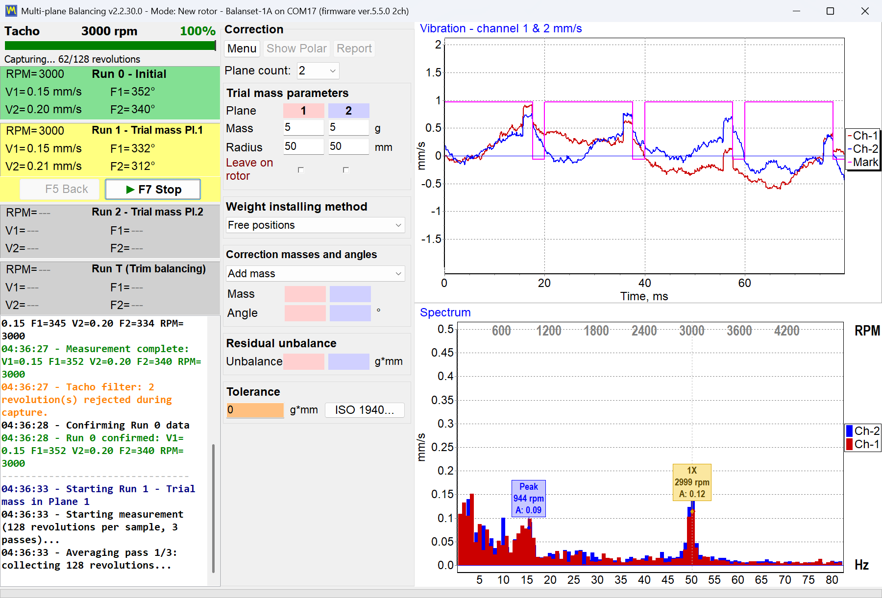
Figure 22. পরিমাপ রান চলাকালীন ব্যালান্সিং ওয়ার্কস্পেস (“F6 - Balancing”): Run 0 - Initial, ট্রায়াল-ভরের রান Run 1 ও Run 2, এবং ট্রিম রান Run T
প্রতিটি মাপজোক সম্পন্ন হওয়ার পর, রোটরের ঘূর্ণন ফ্রিকোয়েন্সির ফলাফল (Nob, সেইসাথে RMS মান (Vo1, ভিo2, ভিo3, ভিo4) এবং পর্যায়গুলি (এফ1, এফ2, এফ3, এফ4) ব্যালান্স করা রোটরের ঘূর্ণন ফ্রিকোয়েন্সিতে কম্পনের প্রোগ্রাম উইন্ডোর সংশ্লিষ্ট ক্ষেত্রগুলিতে সংরক্ষিত হয়। পঞ্চম রানের পরে (Weight in Plane 4), পোলার প্লট সহ ব্যালান্সিং ফলাফল (চিত্র 23 দেখুন) প্রদর্শিত হয়, যা ভরের গণনাকৃত মান প্রদর্শন করে (M1, এম2, এম3, এম4) এবং ইনস্টলেশন কোণ (f1, f2, f3, f4) এর ভারসাম্যহীনতার জন্য ক্ষতিপূরণের জন্য চারটি প্লেনে রটারে ইনস্টল করা প্রয়োজন সংশোধনমূলক ওজনগুলির।
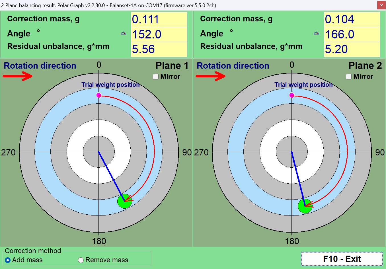
চিত্র 23। ব্যালান্সিং ফলাফলের polar plot: প্রতিটি প্লেনের জন্য গণনাকৃত correction mass ও কোণ, ট্রায়াল ওজনের অবস্থান থেকে ঘূর্ণনের দিকে পরিমাপ করা হয়েছে
সতর্কতা! : After completing the measurement process during the fifth run of the balanced machine, it is necessary to stop the rotor’s rotation and remove the previously installed trial weight. Only after this can you proceed with installing (or removing) the corrective weights on the rotor.
The angular position for adding (or removing) the corrective weight on the rotor in the polar coordinate system is measured from the location of the trial weight installation. The angle measurement direction coincides with the rotor’s rotation direction. In the case of balancing by blades, the blade of the balanced rotor conditionally considered as the 1st blade coincides with the trial weight installation location. The numbering direction of the blades indicated on the computer display follows the rotor’s rotation direction.
প্রোগ্রামের এই সংস্করণে, ডিফল্টভাবে ধরে নেওয়া হয় যে সংশোধনকারী ওজন রোটরে যোগ করা হবে। এটি “Add mass” ফিল্ডে সেট করা চিহ্ন দ্বারা নির্দেশিত। যদি ওজন অপসারণ করে (যেমন, ড্রিলিং করে) ভারসাম্যহীনতা সংশোধন করা প্রয়োজন হয়, তাহলে মাউস ব্যবহার করে “Remove mass” ফিল্ডে চিহ্ন সেট করুন, এরপর সংশোধনকারী ওজনের কৌণিক অবস্থান স্বয়ংক্রিয়ভাবে 180 ডিগ্রি পরিবর্তিত হবে।
ব্যালান্স করা রোটরে সংশোধনী ওজন স্থাপন করার পরে, ব্যালান্সিং অপারেশনের কার্যকারিতা যাচাই করতে ট্রিম রান (Run T) সম্পাদন করুন। ট্রিম রান সম্পন্ন হওয়ার পরে, রোটরের ঘূর্ণন ফ্রিকোয়েন্সির (Nob) এবং RMS মান (Vo1, ভিo2, ভিo3, ভিo4) এবং পর্যায়গুলি (এফ1, এফ2, এফ3, এফ4) ব্যালেন্সকৃত রোটরের ঘূর্ণন ফ্রিকোয়েন্সিতে কম্পন সংরক্ষণ করা হয়। একই সাথে, ব্যালেন্সিং ফলাফল (চিত্র ২৩ দেখুন) আপডেট করা হয়, যা রোটরে ইনস্টল (বা অপসারণ) করা প্রয়োজন এমন অতিরিক্ত সংশোধনকারী ওজনের গণনাকৃত প্যারামিটার প্রদর্শন করে যাতে এর অবশিষ্ট ভারসাম্যহীনতা পূরণ করা যায়। উপরন্তু, এই ওয়ার্কস্পেস ব্যালেন্সিংয়ের পরে অর্জিত অবশিষ্ট ভারসাম্যহীনতার মান দেখায়। যদি ব্যালেন্সকৃত রোটরের অবশিষ্ট কম্পন এবং/অথবা অবশিষ্ট ভারসাম্যহীনতার মান প্রযুক্তিগত ডকুমেন্টেশনে নির্দিষ্ট সহনশীলতার প্রয়োজনীয়তা পূরণ করে, তাহলে ব্যালেন্সিং প্রক্রিয়া সম্পন্ন করা যেতে পারে। অন্যথায়, ব্যালেন্সিং প্রক্রিয়া চালিয়ে যাওয়া যেতে পারে। এই পদ্ধতি ব্যালেন্সকৃত রোটরে সংশোধনকারী ওজন ইনস্টল (অপসারণ) করার সময় ঘটতে পারে এমন সম্ভাব্য ত্রুটি ধারাবাহিক আসন্নীকরণের মাধ্যমে সংশোধন করতে দেয়।
যদি ব্যালান্সিং প্রক্রিয়া চলতে থাকে, তাহলে ব্যালান্সিং ফলাফলে দেখানো গণনাকৃত প্যারামিটার অনুযায়ী ব্যালান্স করা রোটরে অতিরিক্ত সংশোধনমূলক ওজন স্থাপন করতে হবে (অথবা অপসারণ করতে হবে)।
পাঁচটি ক্যালিব্রেশন রানের ফলাফল থেকে গণনা করা রোটর ব্যালান্সিং কোয়েফিসিয়েন্ট (ডাইনামিক ইনফ্লুয়েন্স কোয়েফিসিয়েন্ট) কম্পিউটারের মেমোরিতে সংরক্ষিত থাকে এবং একই ধরনের রোটর ব্যালান্স করার সময় “Load Coefficients” ফাংশন দিয়ে পুনরায় ব্যবহার করা যায়।
7. অনমনীয় রটারগুলির জন্য ভারসাম্যপূর্ণ নির্ভুলতা ক্লাসের প্রস্তাবিত
নিচের গ্রেডগুলো হলো ISO 1940-1-এর balance quality grade G, যা মান পরিবর্তন ছাড়াই ISO 21940-11:2016 দ্বারা প্রতিস্থাপিত হয়েছে। গ্রেডটি এভাবে সংজ্ঞায়িত: G = eper·Ω, যেখানে eper হলো অনুমোদিত নির্দিষ্ট অবশিষ্ট ভারসাম্যহীনতা (g·mm/kg = µm) এবং Ω = 2πn/60 হলো সার্ভিস কৌণিক বেগ (rad/s)। অনুমোদিত অবশিষ্ট ভারসাম্যহীনতা এভাবে পাওয়া যায় Uper = 9549·G·M/n [g·mm], সংশোধন প্লেনগুলোর মধ্যে বিভক্ত। দেখুন আমাদের ISO 1940-1 গ্লোসারি এন্ট্রি।
রোড-ভেহিকেল ড্রাইভশ্যাফটের জন্য ডিফল্ট গ্রেড হলো G 40; G 16 প্রযোজ্য যখন ড্রয়িং বা OEM স্পেসিফিকেশন বিশেষ প্রয়োজনীয়তা দাবি করে। লক্ষণীয় যে অবশিষ্ট ভারসাম্যহীনতা এবং কম্পন পৃথক গ্রহণযোগ্যতা মানদণ্ড: সংযোজিত মেশিনের কম্পন ISO 20816 (পূর্বে ISO 10816) অনুসারে মূল্যায়ন করা হয় — আমাদের দেখুন ISO 10816-1 গ্লোসারি এন্ট্রি।
G-গ্রেড টেবিল শুধুমাত্র দৃঢ় রোটরের জন্য প্রযোজ্য — যে রোটরগুলির সার্ভিস গতি প্রথম বেন্ডিং ক্রিটিক্যাল গতির প্রায় 0.5…0.7-এর নিচে থাকে। দীর্ঘ ড্রাইভশ্যাফট (2 m এবং তার বেশি, এবং ইন্টারমিডিয়েট সাপোর্টযুক্ত যেকোনো শ্যাফট) সেই সীমার কাছাকাছি পৌঁছাতে পারে: সার্ভিস গতি এবং ব্যালেন্সিং গতি উভয়ের বিপরীতে শ্যাফটের প্রথম ক্রিটিক্যাল গতি পরীক্ষা করুন। যদি শ্যাফট গতিতে নমনীয় হয়, তাহলে একটি মোডাল / মাল্টি-স্পিড প্রক্রিয়া ব্যবহার করুন (ISO 21940-12) — একটি দুই-তল দৃঢ়-রোটর সংশোধন ধরে রাখবে না।
সারণী 2. অনমনীয় রটারগুলির জন্য ভারসাম্যপূর্ণ নির্ভুলতা ক্লাসের প্রস্তাবিত।

| মেশিনের ধরন (রোটার) | ব্যালেন্সিং অ্যাকুরেসি ক্লাস | ভারসাম্য গুণমান গ্রেড G = eper·Ω, mm/s |
|---|---|---|
| বড় কম-গতির সামুদ্রিক ডিজেল ইঞ্জিনের জন্য ক্র্যাঙ্কশ্যাফ্ট (গঠনগতভাবে ভারসাম্যহীন) চালান (পিস্টনের গতি 9 m/s) এর চেয়ে কম | G 4000 | 4000 |
| বড় কম-গতির সামুদ্রিক ডিজেল ইঞ্জিনের জন্য ক্র্যাঙ্কশ্যাফ্ট (গঠনগতভাবে ভারসাম্যপূর্ণ) চালান (পিস্টনের গতি 9 m/s) এর কম | G 1600 | 1600 |
| কম্পন বিচ্ছিন্নকারীতে ক্র্যাঙ্কশ্যাফ্ট (গঠনগতভাবে ভারসাম্যহীন) চালান | G 630 | 630 |
| অনমনীয় সমর্থনে ক্র্যাঙ্কশ্যাফ্ট (গঠনগতভাবে ভারসাম্যহীন) চালান | G 250 | 250 |
| যাত্রীবাহী গাড়ি, ট্রাক এবং লোকোমোটিভগুলির জন্য একত্রিত ইঞ্জিনগুলি | G 100 | 100 |
| কম্পন বিচ্ছিন্নকারীতে ক্র্যাঙ্কশ্যাফ্ট (গঠনগতভাবে সুষম) চালান | G 40 | 40 |
| গাড়ির চাকা, হুইল রিম, হুইল সেট, ড্রাইভ শ্যাফট (কার্ডান শ্যাফট) | G 40 | 40 |
| কৃষি মেশিন | G 16 | 16 |
| অনমনীয় সমর্থনে ক্র্যাঙ্কশ্যাফ্ট (সুষম) চালান | G 16 | 16 |
| ক্রাশার | G 16 | 16 |
| বিশেষ প্রয়োজনীয়তাসহ ড্রাইভ শ্যাফট (প্রোপেলার / কার্ডান শ্যাফট) | G 16 | 16 |
| বিমান গ্যাস টারবাইন | G 6.3 | 6.3 |
| সেন্ট্রিফিউজ (বিভাজক, বসতি স্থাপনকারী) | G 6.3 | 6.3 |
| বৈদ্যুতিক মোটর এবং জেনারেটর (অন্তত 80 মিমি শ্যাফ্টের উচ্চতা সহ) সর্বাধিক নামমাত্র ঘূর্ণন গতি 950 মিনিট পর্যন্ত-1 | G 6.3 | 6.3 |
| কম 80 মিমি একটি শ্যাফ্ট উচ্চতা সঙ্গে বৈদ্যুতিক মোটর | G 6.3 | 6.3 |
| ফ্যান | G 6.3 | 6.3 |
| গিয়ার ড্রাইভ | G 6.3 | 6.3 |
| সাধারণ-উদ্দেশ্য মেশিন | G 6.3 | 6.3 |
| ধাতু কাটার মেশিন | G 6.3 | 6.3 |
| কাগজ তৈরির মেশিন | G 6.3 | 6.3 |
| পাম্প | G 6.3 | 6.3 |
| টার্বোচার্জার | G 6.3 | 6.3 |
| জলের টারবাইন | G 6.3 | 6.3 |
| কম্প্রেসর | G 6.3 | 6.3 |
| কম্পিউটার-নিয়ন্ত্রিত ড্রাইভ | G 2.5 | 2.5 |
| বৈদ্যুতিক মোটর এবং জেনারেটর (একটি শ্যাফ্টের উচ্চতা কমপক্ষে 80 মিমি) যার সর্বাধিক নামমাত্র ঘূর্ণন গতি 950 মিনিটের বেশি-1 | G 2.5 | 2.5 |
| গ্যাস ও বাষ্প টারবাইন | G 2.5 | 2.5 |
| ধাতু কাটিয়া মেশিন ড্রাইভ | G 2.5 | 2.5 |
| টেক্সটাইল মেশিন | G 2.5 | 2.5 |
| অডিও এবং ভিডিও সরঞ্জাম ড্রাইভ | জি ঘ | 1 |
| গ্রাইন্ডিং মেশিন ড্রাইভস | জি ঘ | 1 |
| উচ্চ-নির্ভুল সরঞ্জামের স্পিন্ডল এবং ড্রাইভ | G 0.4 | 0.4 |
ড্রাইভ শাফ্ট ভারসাম্যকরণ সম্পর্কে প্রায়শই জিজ্ঞাসিত প্রশ্নাবলী
ড্রাইভ শাফ্ট ভারসাম্যকরণ কী?
ড্রাইভ শাফ্ট ভারসাম্যকরণ হল ড্রাইভ শাফ্টে যেকোনো ভর অসাম্য সংশোধন করার প্রক্রিয়া যাতে এটি কম্পন সৃষ্টি না করে মসৃণভাবে ঘূর্ণায়মান হয়। এতে শাফ্টের এক পাশে কোথায় ভারী তা পরিমাপ করা এবং তারপর সেই অসাম্য প্রতিহত করার জন্য ওজনের ছোট পরিমাণ যোগ বা অপসারণ করা (উদাহরণস্বরূপ, ভারসাম্যকরণ ওজন ঝালাই করা) জড়িত। একটি ভারসাম্যপ্রাপ্ত ড্রাইভ শাফ্ট সমানভাবে চলে, যা অত্যধিক কম্পন এবং যানবাহন উপাদানে পরিধান প্রতিরোধ করে।
ড্রাইভ শাফ্ট ভারসাম্যকরণ কেন গুরুত্বপূর্ণ?
একটি অসাম্যপ্রাপ্ত ড্রাইভ শাফ্ট শক্তিশালী কম্পন সৃষ্টি করতে পারে, বিশেষ করে নির্দিষ্ট গতিতে, এবং ত্বরণ বা গিয়ার স্থানান্তরের সময় ঠকঠক শব্দ সৃষ্টি করতে পারে। সময়ের সাথে সাথে, এই কম্পনগুলি বিয়ারিং, সর্বজনীন যৌগ এবং অন্যান্য ড্রাইভট্রেইন উপাদানের ক্ষতি করতে পারে। ড্রাইভ শাফ্ট ভারসাম্যকরণ এই কম্পনগুলি নির্মূল করে, আরও মসৃণ যাত্রা নিশ্চিত করে, অংশগুলিতে চাপ হ্রাস করে এবং ব্যয়বহুল ক্ষতি বা ডাউনটাইম প্রতিরোধ করে।
একটি অসাম্যপ্রাপ্ত ড্রাইভ শাফ্টের সাধারণ লক্ষণগুলি কী কী?
একটি অসাম্যপ্রাপ্ত বা ত্রুটিপূর্ণ ড্রাইভ শাফ্টের সাধারণ লক্ষণগুলির মধ্যে রয়েছে যানবাহনের মেঝে বা আসনে উল্লেখযোগ্য কম্পন বা কাঁপুনি যা বিশেষ করে গতি বৃদ্ধির সাথে অনুভূত হয়। আপনি গিয়ার স্থানান্তরের সময় বা ত্বরণ এবং হ্রাসকরণের সময়ও ঘাড় বা ঝনঝনানোর শব্দ শুনতে পাবেন। কিছু ক্ষেত্রে, সর্বজনীন যৌগ অসাম্যের কারণে অতিরিক্ত তাপ হতে পারে। যদি আপনি এই চিহ্নগুলি লক্ষ্য করেন, তবে সম্ভবত ড্রাইভ শাফ্টের ভারসাম্যকরণ বা মেরামতের প্রয়োজন।
আপনি ড্রাইভ শাফ্ট কীভাবে ভারসাম্য করেন?
ড্রাইভশ্যাফট ব্যালেন্সিং সাধারণত একটি বিশেষায়িত ব্যালেন্সিং মেশিন ব্যবহার করে করা হয়। ড্রাইভশ্যাফট মাউন্ট করা হয় এবং উচ্চ গতিতে ঘোরানো হয় যখন সেন্সরগুলি যেকোনো ভারসাম্যহীনতা শনাক্ত করে। এরপর একজন টেকনিশিয়ান মেশিনের রিডিং-এর ভিত্তিতে নির্দিষ্ট অবস্থানে ড্রাইভশ্যাফটে ছোট ওজন সংযুক্ত করেন (বা উপাদান অপসারণ করেন)। এই প্রক্রিয়া পুনরাবৃত্তি করা হয় যতক্ষণ না ড্রাইভশ্যাফট উল্লেখযোগ্য কম্পন ছাড়া ঘোরে। Balanset-4A-এর মতো আধুনিক সিস্টেম এই প্রক্রিয়াকে গাইড করতে পারে এবং নিখুঁত ব্যালেন্সিংয়ের জন্য কোথায় এবং কতটা ওজন যোগ করতে হবে তা নির্ভুলভাবে গণনা করতে পারে।
উপসংহার
উপসংহারে, সঠিক ড্রাইভ শাফ্ট ভারসাম্যকরণ নিরাপত্তা, কর্মক্ষমতা এবং খরচ সাশ্রয়ের জন্য অপরিহার্য। আনব্যালেন্স শনাক্ত ও সংশোধন করার মাধ্যমে, আপনি যন্ত্রাংশের অপ্রয়োজনীয় ক্ষয় প্রতিরোধ করেন, ক্ষতিকর বিকল হওয়া এড়ান, এবং সর্বোত্তম মেশিন পারফরম্যান্স বজায় রাখেন। আমাদের Balanset-1A এবং Balanset-4A ডিভাইসের মতো আধুনিক ব্যালান্সিং সিস্টেম এই প্রক্রিয়াকে কার্যকর করে তোলে, এমনকি ছোট ওয়ার্কশপগুলিকেও পেশাদার ফলাফল অর্জনে সাহায্য করে।
যদি আপনি ক্রমাগত ড্রাইভশাফ্ট কম্পন মোকাবেলা করছেন বা একটি নির্ভরযোগ্য ভারসাম্যকরণ সমাধান প্রয়োজন, দেরি করবেন না। এই গাইডে বর্ণিত পদক্ষেপগুলি প্রয়োগ করুন বা সহায়তার জন্য আমাদের বিশেষজ্ঞদের সাথে পরামর্শ করুন। সঠিক পদ্ধতি এবং সরঞ্জামের সাথে, আপনি আপনার ড্রাইভশাফটকে বছরের পর বছর মসৃণভাবে এবং নির্ভরযোগ্যভাবে চলমান নিশ্চিত করতে পারেন। আমাদের সাথে যোগাযোগ করুন আরও জানতে বা আপনার প্রয়োজনের জন্য সেরা ড্রাইভ শাফ্ট ভারসাম্যকরণ সরঞ্জাম অন্বেষণ করতে।








Nikolai Shelkovenko
Nikolai Shelkovenko একজন কম্পন বিশ্লেষণ প্রকৌশলী এবং Vibromera-এর প্রতিষ্ঠাতা ও প্রধান নির্বাহী কর্মকর্তা (CEO)। গত ১৫ বছরেরও বেশি সময় ধরে তিনি টেস্ট বেঞ্চে নয়, বরং সরাসরি কর্মক্ষেত্রে ঘূর্ণায়মান যন্ত্রপাতি ব্যালেন্স করে আসছেন: মালচার, শিল্প পাখা, ক্রাশার, সেন্ট্রিফিউজ, শ্যাফট ও স্পিন্ডল। এই কাজ থেকেই Balanset যন্ত্রগুলোর জন্ম — এগুলো এমনভাবে তৈরি যাতে একজন বিশেষজ্ঞ সহজেই যন্ত্রের কাছে বহন করে নিয়ে যেতে পারেন এবং সাইটে একা ব্যবহার করতে পারেন, ল্যাবরেটরি যন্ত্রপাতি হিসেবে নয়। Vibromera প্রতিষ্ঠিত হয় ২০১৭ সালে এবং ২০২৩ সাল থেকে এর সদর দপ্তর পোর্তো, পর্তুগালে অবস্থিত। Balanset লাইনের উন্নয়ন, সংযোজন ও সহায়তা — সবকিছু এখানেই হয়। প্রধান যন্ত্রটি হলো Balanset-1A, যা একক ও দ্বৈত-তল ব্যালেন্সিং এবং কম্পন নির্ণয়ের জন্য একটি পোর্টেবল অ্যানালাইজার। Nikolai ব্যক্তিগতভাবে গ্রাহক সহায়তা, কঠিন ব্যালেন্সিং সমস্যার সমাধান এবং সফটওয়্যার উন্নয়নে যুক্ত থাকেন। তিনি বিশ্বজুড়ে গ্রাহকদের সাথে যেকোনো ভাষায় কাজ করেন।


0টি মন্তব্য