การทรงตัวเครื่องจักรด้วยมือของคุณเอง
บรรณาธิการและผู้แปล: Nikolai Andreevich Shelkovenko และ ChatGPT
คู่มือทางเทคนิคฉบับสมบูรณ์สำหรับการสร้างเครื่องปรับสมดุลระดับมืออาชีพ เรียนรู้เกี่ยวกับการออกแบบตลับลูกปืนแบบอ่อนและแบบแข็ง การคำนวณแกนหมุน ระบบรองรับ และการบูรณาการอุปกรณ์วัด.


Table of Contents
1. Introduction
(Why was there a need to write this work?)
จากการวิเคราะห์โครงสร้างการบริโภคของอุปกรณ์ปรับสมดุลที่ผลิตโดยบริษัทจำกัด "Kinematics" (Vibromera) พบว่าประมาณ 301,000 เครื่องถูกซื้อไปใช้เป็นระบบวัดและคำนวณแบบอยู่กับที่สำหรับเครื่องจักรและ/หรือแท่นวางปรับสมดุล สามารถระบุกลุ่มผู้บริโภค (ลูกค้า) ของอุปกรณ์ของเราได้สองกลุ่ม.
The first group includes enterprises that specialize in the mass production of balancing machines and selling them to external customers. These enterprises employ highly qualified specialists with deep knowledge and extensive experience in designing, manufacturing, and operating various types of balancing machines. The challenges that arise in interactions with this group of consumers are most often related to adapting our measuring systems and software to existing or newly developed machines, without addressing issues of their structural execution.
The second group consists of consumers who develop and manufacture machines (stands) for their own needs. This approach is mostly explained by the desire of independent manufacturers to reduce their own production costs, which in some cases can decrease by two to three times or more. This group of consumers often lacks proper experience in creating machines and typically relies on the use of common sense, information from the internet, and any available analogs in their work.
Interacting with them raises many questions, which, in addition to additional information about the measuring systems of balancing machines, cover a wide range of issues related to the structural execution of the machines, methods of their installation on the foundation, selection of drives, and achieving proper balancing accuracy, etc.
เนื่องจากผู้บริโภคกลุ่มใหญ่ให้ความสนใจอย่างมากในประเด็นเกี่ยวกับการผลิตเครื่องปรับสมดุลด้วยตนเอง ผู้เชี่ยวชาญจากบริษัท "Kinematics" (Vibromera) จึงได้รวบรวมข้อมูลพร้อมข้อคิดเห็นและคำแนะนำเกี่ยวกับคำถามที่พบบ่อยที่สุด.
2. Types of Balancing Machines (Stands) and Their Design Features
เครื่องปรับสมดุลเป็นอุปกรณ์ทางเทคโนโลยีที่ออกแบบมาเพื่อขจัดความไม่สมดุลแบบคงที่หรือแบบไดนามิกของโรเตอร์เพื่อวัตถุประสงค์ต่างๆ โดยประกอบด้วยกลไกที่เร่งความเร็วโรเตอร์ที่ปรับสมดุลแล้วให้มีความถี่การหมุนที่กำหนด และระบบวัดและคำนวณเฉพาะทางที่ใช้ในการกำหนดมวลและการจัดวางตุ้มน้ำหนักแก้ไขที่จำเป็นเพื่อชดเชยความไม่สมดุลของโรเตอร์.
ส่วนประกอบทางกลของเครื่องจักรโดยทั่วไปประกอบด้วยโครงฐานซึ่งติดตั้งเสารองรับ (แบริ่ง) เสาเหล่านี้ใช้สำหรับยึดผลิตภัณฑ์ที่ปรับสมดุลแล้ว (โรเตอร์) และมีกลไกขับเคลื่อนสำหรับหมุนโรเตอร์ ในระหว่างกระบวนการปรับสมดุล ซึ่งดำเนินการในขณะที่ผลิตภัณฑ์กำลังหมุน เซ็นเซอร์ของระบบวัด (ซึ่งประเภทขึ้นอยู่กับการออกแบบของเครื่องจักร) จะบันทึกการสั่นสะเทือนในแบริ่งหรือแรงที่กระทำต่อแบริ่ง.
The data obtained in this manner allows for determining the masses and installation locations of the corrective weights necessary to compensate for the imbalance.
Currently, two types of balancing machine (stand) designs are most prevalent:
- Soft Bearing machines (with flexible supports);
- Hard Bearing machines (with rigid supports).
2.1. Soft Bearing Machines and Stands
The fundamental feature of Soft Bearing balancing machines (stands) is that they have relatively flexible supports, made on the basis of spring suspensions, spring-mounted carriages, flat or cylindrical spring supports, etc. The natural frequency of these supports is at least 2-3 times lower than the rotation frequency of the balanced rotor mounted on them. A classic example of the structural execution of flexible Soft Bearing supports can be seen in the support of the machine model DB-50, a photograph of which is shown in Figure 2.1.

Figure 2.1. Support of the balancing machine model DB-50.
As shown in Figure 2.1, the movable frame (slider) 2 is attached to the stationary posts 1 of the support using a suspension on strip springs 3. Under the influence of the centrifugal force caused by the imbalance of the rotor installed on the support, the carriage (slider) 2 can perform horizontal oscillations relative to the stationary post 1, which are measured using a vibration sensor.
The structural execution of this support ensures achieving a low natural frequency of carriage oscillations, which can be around 1-2 Hz. This allows for the balancing of the rotor over a wide range of its rotational frequencies, starting from 200 RPM. This feature, along with the relative simplicity of manufacturing such supports, makes this design attractive to many of our consumers who manufacture balancing machines for their own needs of various purposes.

รูปที่ 2.2. แท่นรองแบริ่งอ่อนของเครื่องปรับสมดุล ผลิตโดย "Polymer LTD" เมืองมาคาชคาลา
ภาพที่ 2.2 แสดงภาพถ่ายของเครื่องปรับสมดุลตลับลูกปืนอ่อนที่มีฐานรองทำจากสปริงช่วงล่าง ซึ่งผลิตขึ้นเพื่อใช้ภายในบริษัท "Polymer LTD" ในเมืองมาคาชคาลา เครื่องจักรนี้ออกแบบมาเพื่อปรับสมดุลลูกกลิ้งที่ใช้ในการผลิตวัสดุพอลิเมอร์.
Figure 2.3 features a photograph of a balancing machine with a similar strip suspension for the carriage, intended for balancing specialized tools.
Figures 2.4.a and 2.4.b show photographs of a homemade Soft Bearing machine for balancing drive shafts, whose supports are also made using strip suspension springs.
Figure 2.5 ภาพนี้แสดงเครื่องปรับสมดุลเทอร์โบชาร์จเจอร์แบบใช้ตลับลูกปืนอ่อน โดยมีส่วนรองรับของตัวเลื่อนก็แขวนอยู่บนสปริงแบบแถบ เครื่องนี้สร้างขึ้นเพื่อใช้งานส่วนตัวของ A. Shahgunyan (เซนต์ปีเตอร์สเบิร์ก) และติดตั้งระบบวัด "Balanset 1".
According to the manufacturer (see Fig. 2.6), this machine provides the capability to balance turbines with residual unbalance not exceeding 0.2 g*mm.

Figure 2.3. Soft Bearing Machine for Balancing Tools with Support Suspension on Strip Springs

Figure 2.4.a. Soft Bearing Machine for Balancing Drive Shafts (Machine Assembled)

Figure 2.4.b. Soft Bearing Machine for Balancing Drive Shafts with Carriage Supports Suspended on Strip Springs. (Leading Spindle Support with Spring Strip Suspension)

Figure 2.5. Soft Bearing Machine for Balancing Turbochargers with Supports on Strip Springs, Manufactured by A. Shahgunyan (St. Petersburg)

รูปที่ 2.6 ภาพหน้าจอของระบบวัด 'Balanset 1' แสดงผลการปรับสมดุลใบพัดกังหันบนเครื่องจักรของ A. Shahgunyan
In addition to the classic version of the Soft Bearing balancing machine supports discussed above, other structural solutions have also become widespread.
Figure 2.7 and 2.8 ภาพถ่ายแสดงเครื่องปรับสมดุลเพลาขับ ซึ่งมีฐานรองรับทำจากสปริงแผ่นเรียบ เครื่องจักรเหล่านี้ผลิตขึ้นเพื่อตอบสนองความต้องการเฉพาะของบริษัทเอกชน "Dergacheva" และบริษัทจำกัด "Tatcardan" ("Kinetics-M") ตามลำดับ.
เครื่องปรับสมดุลแบริ่งแบบอ่อนที่มีฐานรองรับแบบนี้ มักถูกผลิตซ้ำโดยผู้ผลิตสมัครเล่น เนื่องจากมีความเรียบง่ายและผลิตได้ง่าย ต้นแบบเหล่านี้โดยทั่วไปจะเป็นเครื่องจักรซีรีส์ VBRF จาก "K. Schenck" หรือเครื่องจักรที่ผลิตในประเทศที่คล้ายคลึงกัน.
The machines shown in Figures 2.7 and 2.8 are designed for balancing two-support, three-support, and four-support drive shafts. They have a similar construction, including:
- a welded bedframe 1, based on two I-beams connected by cross ribs;
- a stationary (front) spindle support 2;
- a movable (rear) spindle support 3;
- one or two movable (intermediate) supports 4. Supports 2 and 3 house spindle units 5 and 6, intended for mounting the balanced drive shaft 7 on the machine.
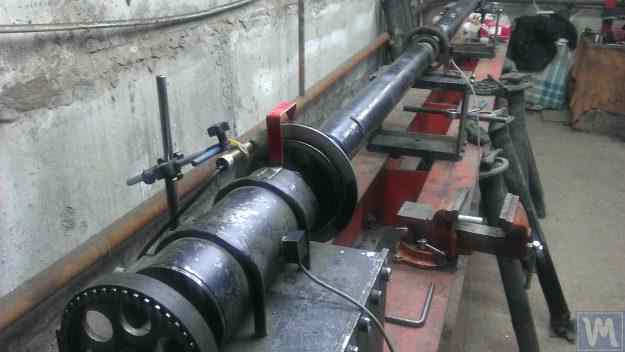
รูปที่ 2.7 เครื่องปรับสมดุลเพลาขับแบบแบริ่งอ่อนของบริษัทเอกชน "เดอร์กาเชวา" พร้อมฐานรองแบบสปริงแผ่นเรียบ
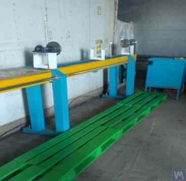
รูปที่ 2.8 เครื่องปรับสมดุลเพลาขับแบบแบริ่งอ่อนของบริษัท "Tatcardan" ("Kinetics-M") พร้อมฐานรองแบบสปริงแบน
Vibration sensors 8 are installed on all supports, which are used to measure the transverse oscillations of the supports. The leading spindle 5, mounted on support 2, is rotated by an electric motor via a belt drive.
Figures 2.9.a and 2.9.b show photographs of the support of the balancing machine, which is based on flat springs.


Figure 2.9. Soft Bearing Balancing Machine Support with Flat Springs
- a) Side view;
- b) Front view
Given that amateur manufacturers frequently use such supports in their designs, it is useful to examine the features of their construction in more detail. As shown in Figure 2.9.a, this support consists of three main components:
- Lower support plate 1: For the front spindle support, the plate is rigidly attached to the guides; for intermediate supports or rear spindle supports, the lower plate is designed as a carriage that can move along the frame guides.
- Upper support plate 2, on which the support units are mounted (roller supports 4, spindles, intermediate bearings, etc.).
- Two flat springs 3, connecting the lower and upper bearing plates.
To prevent the risk of increased vibration of the supports during operation, which can occur during the acceleration or deceleration of the balanced rotor, the supports may include a locking mechanism (see Fig. 2.9.b). This mechanism consists of a rigid bracket 5, which can be engaged by an eccentric lock 6 connected to one of the flat springs of the support. When the lock 6 and bracket 5 are engaged, the support is locked, eliminating the risk of increased vibration during acceleration and deceleration.
When designing supports made with flat (plate) springs, the machine manufacturer must assess the frequency of their natural oscillations, which depends on the stiffness of the springs and the mass of the balanced rotor. Knowing this parameter allows the designer to consciously choose the range of operational rotational frequencies of the rotor, avoiding the danger of resonant oscillations of the supports during balancing.
Recommendations for calculating and experimentally determining the natural frequencies of oscillations of supports, as well as other components of balancing machines, are discussed in Section 3.
As noted earlier, the simplicity and manufacturability of the support design using flat (plate) springs attract amateur developers of balancing machines for various purposes, including machines for balancing crankshafts, automotive turbocharger rotors, etc.
ตัวอย่างเช่น ภาพที่ 2.10.a และ 2.10.b แสดงภาพร่างโดยทั่วไปของเครื่องจักรที่ออกแบบมาเพื่อปรับสมดุลโรเตอร์ของเทอร์โบชาร์จเจอร์ เครื่องจักรนี้ผลิตขึ้นและใช้งานภายในบริษัท LLC "SuraTurbo" ในเมืองเพนซา.

2.10.a. Machine for Balancing Turbocharger Rotors (Side View)

2.10.b. Machine for Balancing Turbocharger Rotors (View from the Front Support Side)
In addition to the previously discussed Soft Bearing balancing machines, relatively simple Soft Bearing stands are sometimes created. These stands allow for high-quality balancing of rotary mechanisms for various purposes with minimal costs.
ด้านล่างนี้จะกล่าวถึงแท่นวางหลายแบบที่สร้างขึ้นบนพื้นฐานของแผ่นเรียบ (หรือโครง) ที่วางอยู่บนสปริงอัดทรงกระบอก โดยปกติแล้วจะเลือกสปริงเหล่านี้ให้ความถี่ธรรมชาติของการสั่นของแผ่นที่มีกลไกปรับสมดุลติดตั้งอยู่บนนั้นต่ำกว่าความถี่การหมุนของโรเตอร์ของกลไกนั้นในระหว่างการปรับสมดุลประมาณ 2 ถึง 3 เท่า.
Figure 2.11 shows a photograph of a stand for balancing abrasive wheels, manufactured for the in-house production by P. Asharin.

Figure 2.11. Stand for Balancing Abrasive Wheels
The stand consists of the following main components:
- Plate 1, mounted on four cylindrical springs 2;
- Electric motor 3, whose rotor also serves as the spindle, on which a mandrel 4 is mounted, used for installing and securing the abrasive wheel on the spindle.
คุณสมบัติที่สำคัญของแท่นนี้คือการมีเซ็นเซอร์วัดชีพจร 5 สำหรับวัดมุมการหมุนของโรเตอร์มอเตอร์ไฟฟ้า ซึ่งใช้เป็นส่วนหนึ่งของระบบวัดของแท่น ("Balanset 2C") เพื่อกำหนดตำแหน่งเชิงมุมสำหรับการกำจัดมวลแก้ไขออกจากล้อขัด.
Figure 2.12 ภาพนี้แสดงขาตั้งที่ใช้สำหรับปรับสมดุลปั๊มสุญญากาศ ขาตั้งนี้ได้รับการพัฒนาตามสั่งโดยบริษัท JSC "Measurement Plant".

รูปที่ 2.12 ขาตั้งสำหรับปรับสมดุลปั๊มสุญญากาศของบริษัท JSC "Measurement Plant""
The basis of this stand also uses Plate 1, mounted on cylindrical springs 2. On Plate 1, a vacuum pump 3 is installed, which has its own electric drive capable of varying speeds widely from 0 to 60,000 RPM. Vibration sensors 4 are mounted on the pump casing, which are used to measure vibrations in two different sections at different heights.
เพื่อให้การวัดการสั่นสะเทือนสอดคล้องกับมุมการหมุนของโรเตอร์ปั๊ม จึงใช้เซ็นเซอร์วัดมุมเฟสเลเซอร์ 5 บนแท่นวาง แม้ว่าโครงสร้างภายนอกของแท่นวางดังกล่าวจะดูเรียบง่าย แต่ก็ช่วยให้สามารถปรับสมดุลใบพัดของปั๊มได้อย่างมีคุณภาพสูงมาก.
ตัวอย่างเช่น ที่ความถี่การหมุนต่ำกว่าวิกฤต ความไม่สมดุลที่เหลืออยู่ของโรเตอร์ปั๊มเป็นไปตามข้อกำหนดที่กำหนดไว้สำหรับคุณภาพความสมดุลระดับ G0.16 ตามมาตรฐาน ISO 1940-1-2007 "การสั่นสะเทือน ข้อกำหนดสำหรับคุณภาพความสมดุลของโรเตอร์แข็ง ส่วนที่ 1 การกำหนดความไม่สมดุลที่อนุญาต""
The residual vibration of the pump casing achieved during balancing at rotational speeds up to 8,000 RPM does not exceed 0.01 mm/sec.
Balancing stands manufactured according to the scheme described above are also effective in balancing other mechanisms, such as fans. Examples of stands designed for balancing fans are shown in Figures 2.13 and 2.14.

Figure 2.13. Stand for Balancing Fan Impellers
คุณภาพของการปรับสมดุลพัดลมที่ทำบนแท่นวางดังกล่าวค่อนข้างสูง ตามที่ผู้เชี่ยวชาญจากบริษัท "Atlant-project" จำกัด ระบุว่า บนแท่นวางที่พวกเขาออกแบบตามคำแนะนำจากบริษัท "Kinematics" จำกัด (ดูรูปที่ 2.14) ระดับการสั่นสะเทือนที่เหลืออยู่เมื่อปรับสมดุลพัดลมอยู่ที่ 0.8 มม./วินาที ซึ่งดีกว่าค่าความคลาดเคลื่อนที่กำหนดไว้สำหรับพัดลมในหมวด BV5 ตามมาตรฐาน ISO 31350-2007 "การสั่นสะเทือน พัดลมอุตสาหกรรม ข้อกำหนดสำหรับคุณภาพการสั่นสะเทือนและการปรับสมดุล" มากกว่าสามเท่า"

รูปที่ 2.14 ขาตั้งสำหรับปรับสมดุลใบพัดพัดลมของอุปกรณ์ป้องกันการระเบิด ผลิตโดยบริษัท "Atlant-project" จำกัด เมืองโพดอลสค์
ข้อมูลที่คล้ายกันซึ่งได้จากบริษัท JSC "Lissant Fan Factory" แสดงให้เห็นว่า ขาตั้งดังกล่าวที่ใช้ในการผลิตพัดลมแบบต่อเนื่อง ช่วยให้มั่นใจได้ว่าการสั่นสะเทือนที่เหลืออยู่จะไม่เกิน 0.1 มม./วินาที อย่างสม่ำเสมอ.
2.2. Hard Bearing Machines
Hard Bearing balancing machines differ from the previously discussed Soft Bearing machines in the design of their supports. Their supports are made in the form of rigid plates with intricate slots (cut-outs). The natural frequencies of these supports significantly (at least 2-3 times) exceed the maximum rotational frequency of the rotor balanced on the machine.
Hard Bearing machines are more versatile than Soft Bearing ones, as they typically allow for high-quality balancing of rotors over a wider range of their mass and dimensional characteristics. An important advantage of these machines is also that they enable high-precision balancing of rotors at relatively low rotational speeds, which can be within the range of 200-500 RPM and lower.
Figure 2.15 ภาพนี้แสดงตัวอย่างเครื่องปรับสมดุลแบริ่งแข็งทั่วไปที่ผลิตโดย "K. Schenk" จากภาพนี้ เห็นได้ชัดว่าชิ้นส่วนแต่ละส่วนของตัวรองรับ ซึ่งเกิดจากร่องที่ซับซ้อน มีความแข็งต่างกัน ภายใต้แรงที่เกิดจากการไม่สมดุลของโรเตอร์ อาจทำให้เกิดการเสียรูป (การเคลื่อนที่) ของบางส่วนของตัวรองรับเมื่อเทียบกับส่วนอื่นๆ (ในภาพที่ 2.15 ส่วนที่แข็งกว่าของตัวรองรับถูกเน้นด้วยเส้นประสีแดง และส่วนที่อ่อนกว่าถูกเน้นด้วยสีน้ำเงิน).
To measure the said relative deformations, Hard Bearing machines can use either force sensors or highly sensitive vibration sensors of various types, including non-contact vibration displacement sensors.

รูปที่ 2.15 เครื่องปรับสมดุลตลับลูกปืนแข็ง โดย "K. Schenk""
จากการวิเคราะห์คำขอจากลูกค้าสำหรับเครื่องมือซีรีส์ "Balanset" พบว่า ความสนใจในการผลิตเครื่องปรับสมดุลตลับลูกปืนแข็งสำหรับใช้ภายในองค์กรนั้นเพิ่มขึ้นอย่างต่อเนื่อง ซึ่งเป็นผลมาจากการเผยแพร่ข้อมูลโฆษณาเกี่ยวกับคุณสมบัติการออกแบบของเครื่องปรับสมดุลที่ผลิตในประเทศอย่างแพร่หลาย โดยผู้ผลิตรายย่อยนำไปใช้เป็นแบบอย่าง (หรือต้นแบบ) ในการพัฒนาผลิตภัณฑ์ของตนเอง.
เรามาพิจารณาเครื่องจักรแบบแบริ่งแข็งรุ่นต่างๆ ที่ผลิตขึ้นเพื่อตอบสนองความต้องการภายในของลูกค้าจำนวนหนึ่งที่ใช้เครื่องมือซีรีส์ "Balanset" กัน.
Figures 2.16.a – 2.16.d ภาพแสดงเครื่องปรับสมดุลเพลาขับแบบแข็ง (Hard Bearing machine) ซึ่งผลิตโดยบริษัท N. Obyedkov (เมือง Magnitogorsk) ดังที่แสดงในรูปที่ 2.16.a เครื่องจักรประกอบด้วยโครงสร้างแข็ง 1 ซึ่งติดตั้งตัวรองรับ 2 (แกนหมุนสองตัวและตัวกลางสองตัว) แกนหมุนหลัก 3 ของเครื่องจักรหมุนโดยมอเตอร์ไฟฟ้าแบบอะซิงโครนัส 4 ผ่านระบบขับเคลื่อนด้วยสายพาน ตัวควบคุมความถี่ 6 ใช้สำหรับควบคุมความเร็วรอบของมอเตอร์ไฟฟ้า 4 เครื่องจักรนี้ติดตั้งระบบวัดและคำนวณ "Balanset 4" 5 ซึ่งประกอบด้วยหน่วยวัด คอมพิวเตอร์ เซ็นเซอร์วัดแรงสี่ตัว และเซ็นเซอร์วัดมุมเฟส (เซ็นเซอร์ไม่ได้แสดงในรูปที่ 2.16.a).

Figure 2.16.a. Hard Bearing Machine for Balancing Drive Shafts, Manufactured by N. Obyedkov (Magnitogorsk)
Figure 2.16.b shows a photograph of the front support of the machine with the leading spindle 3, which is driven, as previously noted, by a belt drive from an asynchronous electric motor 4. This support is rigidly mounted on the frame.

Figure 2.16.b. Front (Leading) Spindle Support.
Figure 2.16.c features a photograph of one of the two movable intermediate supports of the machine. This support rests on slides 7, allowing for its longitudinal movement along the frame guides. This support includes a special device 8, designed for installing and adjusting the height of the intermediate bearing of the balanced drive shaft.

Figure 2.16.c. Intermediate Movable Support of the Machine
Figure 2.16.d ภาพนี้แสดงส่วนของตัวรองรับแกนหมุนด้านหลัง (ด้านขับเคลื่อน) ซึ่งเช่นเดียวกับตัวรองรับตรงกลาง ช่วยให้สามารถเคลื่อนที่ไปตามรางนำของโครงเครื่องจักรได้.

Figure 2.16.d. Rear (Driven) Spindle Support.
All the supports discussed above are vertical plates mounted on flat bases. The plates feature T-shaped slots (see Fig. 2.16.d), which divide the support into an inner part 9 (more rigid) and an outer part 10 (less rigid). The differing stiffness of the inner and outer parts of the support may result in relative deformation of these parts under the forces of unbalance from the balanced rotor.
Force sensors are typically used to measure the relative deformation of the supports in homemade machines. An example of how a force sensor is installed on a Hard Bearing balancing machine support is shown in Figure 2.16.e. As seen in this figure, the force sensor 11 is pressed against the side surface of the inner part of the support by a bolt 12, which passes through a threaded hole in the outer part of the support.
To ensure even pressure of bolt 12 across the entire plane of the force sensor 11, a flat washer 13 is placed between it and the sensor.

Figure 2.16.d. Example of Force Sensor Installation on a Support.
ในระหว่างการทำงานของเครื่องจักร แรงที่ไม่สมดุลจากโรเตอร์ที่สมดุลจะกระทำผ่านหน่วยรองรับ (แกนหมุนหรือแบริ่งกลาง) ไปยังส่วนนอกของตัวรองรับ ซึ่งจะเริ่มเคลื่อนที่ (เสียรูป) เป็นวงจรสัมพันธ์กับส่วนในด้วยความถี่ของการหมุนของโรเตอร์ ส่งผลให้เกิดแรงแปรผันกระทำต่อเซ็นเซอร์ 11 ซึ่งเป็นสัดส่วนกับแรงที่ไม่สมดุล ภายใต้อิทธิพลนี้ สัญญาณไฟฟ้าที่เป็นสัดส่วนกับขนาดของความไม่สมดุลของโรเตอร์จะถูกสร้างขึ้นที่เอาต์พุตของเซ็นเซอร์วัดแรง.
สัญญาณจากเซ็นเซอร์วัดแรงที่ติดตั้งอยู่บนฐานรองรับทั้งหมด จะถูกส่งเข้าสู่ระบบวัดและประมวลผลของเครื่องจักร ซึ่งจะนำไปใช้ในการกำหนดค่าพารามิเตอร์ของตุ้มน้ำหนักปรับแก้.
Figure 2.17.a. ภาพนี้แสดงเครื่องจักรเฉพาะทางสำหรับปรับสมดุลเพลา "สกรู" ที่เรียกว่าเครื่องจักร Hard Bearing เครื่องจักรนี้ผลิตขึ้นเพื่อใช้ภายในบริษัท LLC "Ufatverdosplav".
As seen in the figure, the spin-up mechanism of the machine has a simplified construction, which consists of the following main components:
- Welded frame 1, serving as the bed;
- Two stationary supports 2, rigidly fixed to the frame;
- Electric motor 3, which drives the balanced shaft (screw) 5 via a belt drive 4.
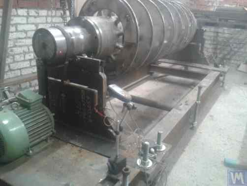
รูปที่ 2.17.ก. เครื่องปรับสมดุลเพลาสกรูแบบตลับลูกปืนแข็ง ผลิตโดยบริษัทจำกัด "Ufatverdosplav""
The supports 2 of the machine are vertically installed steel plates with T-shaped slots. At the top of each support, there are support rollers manufactured using rolling bearings, on which the balanced shaft 5 rotates.
เพื่อวัดการเสียรูปของแท่นรองรับที่เกิดขึ้นภายใต้การกระทำของความไม่สมดุลของโรเตอร์ จึงใช้เซ็นเซอร์วัดแรง 6 (ดูรูปที่ 2.17.b) ซึ่งติดตั้งอยู่ในร่องของแท่นรองรับ เซ็นเซอร์เหล่านี้เชื่อมต่อกับอุปกรณ์ "Balanset 1" ซึ่งใช้ในเครื่องจักรนี้เป็นระบบวัดและคำนวณ.
แม้ว่ากลไกการหมุนของเครื่องจักรจะค่อนข้างเรียบง่าย แต่ก็ช่วยให้สามารถปรับสมดุลของสกรูได้อย่างมีคุณภาพสูง ซึ่งดังที่เห็นในรูปที่ 2.17.a. สกรูเหล่านี้มีพื้นผิวเป็นเกลียวที่ซับซ้อน.
จากข้อมูลของบริษัทจำกัด "Ufatverdosplav" ระบุว่า ความไม่สมดุลเริ่มต้นของสกรูในเครื่องจักรนี้ลดลงเกือบ 50 เท่าในระหว่างกระบวนการปรับสมดุล.

Figure 2.17.b. Hard Bearing Machine Support for Balancing Screw Shafts with Force Sensor
ค่าความไม่สมดุลคงเหลือที่ได้คือ 3552 กรัม*มม. (19.2 กรัม ที่รัศมี 185 มม.) ในระนาบแรกของสกรู และ 2220 กรัม*มม. (12.0 กรัม ที่รัศมี 185 มม.) ในระนาบที่สอง สำหรับโรเตอร์ที่มีน้ำหนัก 500 กก. และทำงานที่ความถี่การหมุน 3500 รอบต่อนาที ค่าความไม่สมดุลนี้สอดคล้องกับระดับ G6.3 ตามมาตรฐาน ISO 1940-1-2007 ซึ่งตรงตามข้อกำหนดที่ระบุไว้ในเอกสารทางเทคนิค.
บริษัท SV Morozov ได้เสนอการออกแบบดั้งเดิม (ดูรูปที่ 2.18) ซึ่งเกี่ยวข้องกับการใช้ฐานเดียวสำหรับการติดตั้งตัวรองรับพร้อมกันสำหรับเครื่องปรับสมดุลตลับลูกปืนแข็งสองเครื่องที่มีขนาดแตกต่างกัน ข้อดีที่เห็นได้ชัดของวิธีการทางเทคนิคนี้ ซึ่งช่วยลดต้นทุนการผลิตของผู้ผลิตได้อย่างมาก ได้แก่:
- Saving production space;
- Use of one electric motor with a variable frequency drive for operating two different machines;
- Use of one measuring system for operating two different machines.

รูปที่ 2.18 เครื่องปรับสมดุลตลับลูกปืนแข็ง (แบบ "แทนเดม") ผลิตโดย SV Morozov
3. Requirements for the Construction of Basic Units and Mechanisms of Balancing Machines
3.1. Bearings
3.1.1. Theoretical Foundations of Bearing Design
ในส่วนก่อนหน้านี้ ได้มีการกล่าวถึงรายละเอียดเกี่ยวกับการออกแบบหลักของตัวรองรับแบบอ่อนและแบบแข็งสำหรับเครื่องปรับสมดุลเครื่องจักรไปแล้ว พารามิเตอร์ที่สำคัญที่ผู้ออกแบบต้องพิจารณาเมื่อออกแบบและผลิตตัวรองรับเหล่านี้คือความถี่ธรรมชาติของการสั่นของตัวรองรับ เนื่องจากจำเป็นต้องวัดไม่เพียงแต่แอมพลิจูดของการสั่น (การเสียรูปเป็นวงจร) ของตัวรองรับเท่านั้น แต่ยังรวมถึงเฟสของการสั่นด้วย ซึ่งจำเป็นสำหรับการคำนวณพารามิเตอร์ของน้ำหนักปรับแก้โดยระบบการวัดและการคำนวณของเครื่องจักร.
หากความถี่ธรรมชาติของฐานรองรับตรงกับความถี่การหมุนของโรเตอร์ที่สมดุล (การสั่นพ้องของฐานรองรับ) การวัดแอมพลิจูดและเฟสของการสั่นสะเทือนอย่างแม่นยำนั้นแทบจะเป็นไปไม่ได้เลย ดังจะเห็นได้จากกราฟที่แสดงการเปลี่ยนแปลงของแอมพลิจูดและเฟสของการสั่นของฐานรองรับเป็นฟังก์ชันของความถี่การหมุนของโรเตอร์ที่สมดุล (ดูรูปที่ 3.1).
From these graphs, it follows that as the rotational frequency of the balanced rotor approaches the natural frequency of the support oscillations (i.e., when the ratio fp/fo is close to 1), there is a significant increase in amplitude associated with the resonance oscillations of the support (see Fig. 3.1.a). Simultaneously, graph 3.1.b shows that in the resonance zone, there is a sharp change in the phase angle ∆F°, which can reach up to 180°.
In other words, when balancing any mechanism in the resonance zone, even small changes in its rotation frequency can lead to significant instability in the measurement results of amplitude and phase of its vibration, leading to errors in calculating the parameters of corrective weights and negatively affecting the quality of balancing.
กราฟข้างต้นยืนยันคำแนะนำก่อนหน้านี้ว่า สำหรับเครื่องจักรที่มีแบริ่งแข็ง ความถี่ในการทำงานของโรเตอร์ที่สูงสุดควรต่ำกว่าความถี่ธรรมชาติของตัวรองรับอย่างน้อย 2-3 เท่า สำหรับเครื่องจักรที่มีแบริ่งอ่อน ความถี่ในการทำงานที่อนุญาตได้ของโรเตอร์ที่สมดุลแล้วควรสูงกว่าความถี่ธรรมชาติของตัวรองรับอย่างน้อย 2-3 เท่า.

Figure 3.1. Graphs showing changes in relative amplitude and phase of vibrations of the balancing machine support as a function of rotational frequency changes.
- Ад – Amplitude of dynamic vibrations of the support;
- e = m*r / M - ความไม่สมดุลเฉพาะจุดของโรเตอร์ที่สมดุล;
- m – Unbalanced mass of the rotor;
- M – Mass of the rotor;
- r – Radius at which the unbalanced mass is located on the rotor;
- fp – Rotational frequency of the rotor;
- fo – Natural frequency of vibrations of the support
Given the information presented, operating the machine in the resonance area of its supports (highlighted in red in Fig. 3.1) is not recommended. The graphs shown in Fig. 3.1 also demonstrate that for the same imbalances of the rotor, the actual vibrations of the Soft Bearing machine supports are significantly lower than those occurring on the Soft Bearing machine supports.
From this, it follows that sensors used to measure vibrations of supports in Hard Bearing machines must have higher sensitivity than those in Soft Bearing machines. This conclusion is well supported by the actual practice of using sensors, which shows that absolute vibration sensors (vibro-accelerometers and/or vibro-velocity sensors), successfully used in Soft Bearing balancing machines, often cannot achieve the necessary balancing quality on Hard Bearing machines.
On these machines, it is recommended to use relative vibration sensors, such as force sensors or highly sensitive displacement sensors.
3.1.2. Estimating Natural Frequencies of Supports Using Calculation Methods
A designer can perform an approximate (estimative) calculation of the natural frequency of a support fo using formula 3.1, by simplistically treating it as a vibrational system with one degree of freedom, which (see Fig. 2.19.a) is represented by a mass M, oscillating on a spring with stiffness K.
The mass M used in the calculation for a symmetric inter-bearing rotor can be approximated by formula 3.2.
โดยที่ Mo คือมวลของส่วนที่เคลื่อนที่ได้ของแท่นรองรับในหน่วยกิโลกรัม; Mr คือมวลของโรเตอร์ที่สมดุลในหน่วยกิโลกรัม; และ n คือจำนวนแท่นรองรับเครื่องจักรที่เกี่ยวข้องกับการปรับสมดุล.
The stiffness K of the support is calculated using formula 3.3 based on the results of experimental studies that involve measuring the deformation ΔL of the support when it is loaded with a static force P (see Figs. 3.2.a and 3.2.b).
โดยที่ ΔL คือการเสียรูปของฐานรองในหน่วยเมตร และ P คือแรงสถิตในหน่วยนิวตัน.
The magnitude of the loading force P can be measured using a force-measuring instrument (e.g., a dynamometer). The displacement of the support ΔL is determined using a device for measuring linear displacements (e.g., a dial indicator).
3.1.3. Experimental Methods for Determining Natural Frequencies of Supports
เนื่องจากการคำนวณความถี่ธรรมชาติของจุดรองรับที่กล่าวถึงข้างต้น ซึ่งดำเนินการโดยใช้วิธีที่ง่ายขึ้น อาจนำไปสู่ข้อผิดพลาดอย่างมาก นักพัฒนาสมัครเล่นส่วนใหญ่จึงนิยมกำหนดค่าพารามิเตอร์เหล่านี้ด้วยวิธีการทดลอง โดยพวกเขาใช้ประโยชน์จากความสามารถของระบบวัดการสั่นสะเทือนที่ทันสมัยของเครื่องปรับสมดุล รวมถึงเครื่องมือในซีรีส์ "Balanset".
3.1.3.1. Determining Natural Frequencies of Supports by Impact Excitation Method
The impact excitation method is the simplest and most common way to determine the natural frequency of vibrations of a support or any other machine component. It is based on the fact that when any object, such as a bell (see Fig. 3.3), is impact-excited, its response manifests as a gradually decaying vibrational response. The frequency of the vibrational signal is determined by the structural characteristics of the object and corresponds to the frequency of its natural vibrations. For impact excitation of vibrations, any heavy tool can be used, such as a rubber mallet or a regular mallet.

Figure 3.3. Diagram of Impact Excitation Used to Determine the Natural Frequencies of an Object
The mass of the hammer should approximately be 10% of the mass of the object being excited. To capture the vibrational response, a vibration sensor should be installed on the object under examination, with its measuring axis aligned with the direction of impact excitation. In some cases, a microphone from a noise measuring device may be used as a sensor to perceive the vibrational response of the object.
การสั่นสะเทือนของวัตถุจะถูกแปลงเป็นสัญญาณไฟฟ้าโดยเซ็นเซอร์ จากนั้นสัญญาณนั้นจะถูกส่งไปยังเครื่องมือวัด เช่น อินพุตของเครื่องวิเคราะห์สเปกตรัม เครื่องมือนี้จะบันทึกฟังก์ชันเวลาและสเปกตรัมของกระบวนการสั่นสะเทือนที่ลดลง (ดูรูปที่ 3.4) การวิเคราะห์ข้อมูลเหล่านี้จะช่วยให้สามารถกำหนดความถี่ของการสั่นสะเทือนตามธรรมชาติของวัตถุได้.

Figure 3.5. Program Interface Showing Time Function Graphs and Spectrum of Decaying Impact Vibrations of the Examined Structure
The analysis of the spectrum graph presented in Figure 3.5 (see the lower part of the work window) shows that the main component of the natural vibrations of the examined structure, determined with reference to the abscissa axis of the graph, occurs at a frequency of 9.5 Hz. This method can be recommended for studies of the natural vibrations of both Soft Bearing and Hard Bearing balancing machine supports.
3.1.3.2. Determining Natural Frequencies of Supports in Coasting Mode
ในบางกรณี ความถี่ธรรมชาติของฐานรองรับสามารถกำหนดได้โดยการวัดแอมพลิจูดและเฟสของการสั่นสะเทือนแบบวนซ้ำ "ขณะหยุดนิ่ง" ในการดำเนินการตามวิธีนี้ โรเตอร์ที่ติดตั้งบนเครื่องจักรที่ตรวจสอบจะถูกเร่งความเร็วไปจนถึงความเร็วรอบสูงสุดในตอนแรก หลังจากนั้นระบบขับเคลื่อนจะถูกตัดการเชื่อมต่อ และความถี่ของแรงรบกวนที่เกี่ยวข้องกับความไม่สมดุลของโรเตอร์จะค่อยๆ ลดลงจากค่าสูงสุดจนถึงจุดหยุด.
In this case, the natural frequencies of supports can be determined by two characteristics:
- By a local jump in vibration amplitude observed in the resonance areas;
- By a sharp change (up to 180°) in the vibration phase observed in the zone of the amplitude jump.
ในอุปกรณ์ซีรีส์ "Balanset" โหมด "Vibrometer" ("Balanset 1") หรือโหมด "Balanset Monitoring" ("Balanset 2C" และ "Balanset 4") สามารถใช้ตรวจจับความถี่ธรรมชาติของวัตถุ "บนชายฝั่ง" ซึ่งช่วยให้สามารถวัดแอมพลิจูดและเฟสของการสั่นสะเทือนแบบวนรอบที่ความถี่การหมุนของใบพัดได้.
นอกจากนี้ ซอฟต์แวร์ "Balanset 1" ยังมีโหมด "Graphs. Coasting" พิเศษ ซึ่งช่วยให้สามารถสร้างกราฟแสดงการเปลี่ยนแปลงของแอมพลิจูดและเฟสของการสั่นสะเทือนของฐานรองรับขณะลอยตัวตามความถี่การหมุนที่เปลี่ยนแปลงไป ทำให้กระบวนการวินิจฉัยเรโซแนนซ์ง่ายขึ้นอย่างมาก.
It should be noted that, for obvious reasons (see section 3.1.1), the method of identifying natural frequencies of supports on the coast can only be used in the case of studying Soft Bearing balancing machines, where the working frequencies of rotor rotation significantly exceed the natural frequencies of supports in the transverse direction.
In the case of Hard Bearing machines, where the working frequencies of rotor rotation exciting the vibrations of supports on the coast are significantly below the natural frequencies of the supports, the use of this method is practically impossible.
3.1.4. Practical Recommendations for Designing and Manufacturing Supports for Balancing Machines
3.1.2. Calculating Natural Frequencies of Supports by Computational Methods
Calculations of the natural frequencies of supports using the above-discussed calculation scheme can be performed in two directions:
- In the transverse direction of the supports, which coincides with the direction of measuring their vibrations caused by the forces of rotor unbalance;
- In the axial direction, coinciding with the axis of rotation of the balanced rotor mounted on the machine supports.
การคำนวณความถี่ธรรมชาติของฐานรองรับในแนวตั้งนั้น จำเป็นต้องใช้เทคนิคการคำนวณที่ซับซ้อนกว่า ซึ่ง (นอกเหนือจากพารามิเตอร์ของฐานรองรับและโรเตอร์ที่สมดุลแล้ว) จะต้องคำนึงถึงพารามิเตอร์ของโครงสร้างและลักษณะเฉพาะของการติดตั้งเครื่องจักรบนฐานรากด้วย วิธีนี้ไม่ได้กล่าวถึงในเอกสารนี้ การวิเคราะห์สูตร 3.1 ช่วยให้ได้คำแนะนำง่ายๆ บางประการที่นักออกแบบเครื่องจักรควรพิจารณาในการปฏิบัติงานจริง โดยเฉพาะอย่างยิ่ง ความถี่ธรรมชาติของฐานรองรับสามารถเปลี่ยนแปลงได้โดยการเปลี่ยนความแข็งและความ/หรือมวล การเพิ่มความแข็งจะเพิ่มความถี่ธรรมชาติของฐานรองรับ ในขณะที่การเพิ่มมวลจะลดลง การเปลี่ยนแปลงเหล่านี้มีความสัมพันธ์แบบไม่เชิงเส้นและผกผันกำลังสอง ตัวอย่างเช่น การเพิ่มความแข็งของฐานรองรับเป็นสองเท่าจะเพิ่มความถี่ธรรมชาติเพียง 1.4 เท่า ในทำนองเดียวกัน การเพิ่มมวลของส่วนที่เคลื่อนที่ได้ของฐานรองรับเป็นสองเท่าจะลดความถี่ธรรมชาติลงเพียง 1.4 เท่า.
3.1.4.1. Soft Bearing Machines with Flat Plate Springs
ในหัวข้อที่ 2.1 และรูปที่ 2.7 - 2.9 ได้กล่าวถึงรูปแบบการออกแบบต่างๆ ของอุปกรณ์รองรับเครื่องปรับสมดุลที่ทำจากสปริงแบนไว้แล้ว จากข้อมูลที่เราได้รับ การออกแบบดังกล่าวส่วนใหญ่ใช้ในเครื่องจักรที่ใช้สำหรับปรับสมดุลเพลาขับ.
ยกตัวอย่างเช่น ลองพิจารณาพารามิเตอร์ของสปริงที่ลูกค้ารายหนึ่ง (บริษัท "Rost-Service" จำกัด เมืองเซนต์ปีเตอร์สเบิร์ก) ใช้ในการผลิตแท่นรองเครื่องจักรของตนเอง เครื่องจักรนี้มีจุดประสงค์เพื่อปรับสมดุลเพลาขับแบบ 2, 3 และ 4 จุดรองรับ โดยมีน้ำหนักไม่เกิน 200 กิโลกรัม ขนาดทางเรขาคณิตของสปริง (ความสูง * ความกว้าง * ความหนา) ที่ใช้ในแท่นรองของแกนหมุนนำและแกนหมุนตามของเครื่องจักร ซึ่งลูกค้าเลือกใช้นั้น มีขนาด 300*200*3 มม. ตามลำดับ.
ความถี่ธรรมชาติของฐานรองที่ไม่มีน้ำหนักบรรทุก ซึ่งกำหนดโดยการทดลองด้วยวิธีการกระตุ้นด้วยแรงกระแทกโดยใช้ระบบวัดมาตรฐานของเครื่อง "Balanset 4" พบว่าอยู่ที่ 11 - 12 เฮิรตซ์ ที่ความถี่ธรรมชาติของการสั่นสะเทือนของฐานรองดังกล่าว ความถี่การหมุนที่แนะนำของโรเตอร์ที่สมดุลในระหว่างการปรับสมดุลไม่ควรต่ำกว่า 22-24 เฮิรตซ์ (1320 – 1440 รอบต่อนาที).
ขนาดทางเรขาคณิตของสปริงแบนที่ผู้ผลิตรายเดียวกันใช้ในส่วนรองรับตรงกลางนั้นมีขนาด 200*200*3 มม. ตามลำดับ ยิ่งไปกว่านั้น จากการศึกษาพบว่าความถี่ธรรมชาติของส่วนรองรับเหล่านี้สูงกว่า โดยอยู่ที่ 13-14 เฮิรตซ์.
จากผลการทดสอบ ผู้ผลิตเครื่องจักรได้รับคำแนะนำให้ปรับความถี่ธรรมชาติของแกนหมุนและตัวรองรับกลางให้เท่ากัน ซึ่งจะช่วยให้การเลือกช่วงความถี่การหมุนในการทำงานของเพลาขับระหว่างการปรับสมดุลทำได้ง่ายขึ้น และหลีกเลี่ยงความไม่เสถียรที่อาจเกิดขึ้นกับค่าที่อ่านได้จากระบบวัดเนื่องจากตัวรองรับเข้าสู่บริเวณการสั่นสะเทือนแบบเรโซแนนซ์.
The methods for adjusting the natural frequencies of vibrations of supports on flat springs are obvious. This adjustment can be achieved by changing the geometric dimensions or shape of the flat springs, which is achieved, for example, by milling longitudinal or transverse slots that reduce their stiffness.
As previously mentioned, verification of the results of such adjustment can be conducted by identifying the natural frequencies of vibrations of the supports using the methods described in sections 3.1.3.1 and 3.1.3.2.
Figure 3.6 presents a classic version of the support design on flat springs, used in one of his machines by A. Sinitsyn. As shown in the figure, the support includes the following components:
- Upper plate 1;
- Two flat springs 2 and 3;
- Lower plate 4;
- Stop bracket 5.

Figure 3.6. Design Variation of a Support on Flat Springs
The upper plate 1 of the support can be used to mount the spindle or an intermediate bearing. Depending on the purpose of the support, the lower plate 4 can be rigidly attached to the machine guides or installed on movable slides, allowing the support to move along the guides. Bracket 5 is used to install a locking mechanism for the support, enabling it to be securely fixed during the acceleration and deceleration of the balanced rotor.
สปริงแบนสำหรับแท่นรองรับเครื่องจักรแบบแบริ่งอ่อนควรทำจากเหล็กแผ่นสปริงหรือเหล็กอัลลอยคุณภาพสูง การใช้เหล็กโครงสร้างทั่วไปที่มีความแข็งแรงคราต่ำนั้นไม่เหมาะสม เนื่องจากอาจเกิดการเสียรูปถาวรภายใต้แรงคงที่และแรงพลวัตในระหว่างการทำงาน ซึ่งจะนำไปสู่การลดความแม่นยำทางเรขาคณิตของเครื่องจักรและอาจทำให้สูญเสียเสถียรภาพของแท่นรองรับได้.
สำหรับเครื่องจักรที่มีมวลโรเตอร์สมดุลไม่เกิน 300 - 500 กิโลกรัม ความหนาของตัวรองรับสามารถเพิ่มขึ้นได้ถึง 30 – 40 มิลลิเมตร และสำหรับเครื่องจักรที่ออกแบบมาเพื่อปรับสมดุลโรเตอร์ที่มีมวลสูงสุดตั้งแต่ 1000 ถึง 3000 กิโลกรัม ความหนาของตัวรองรับสามารถสูงถึง 50 – 60 มิลลิเมตรหรือมากกว่านั้น จากการวิเคราะห์ลักษณะไดนามิกของตัวรองรับดังกล่าว พบว่าความถี่การสั่นสะเทือนตามธรรมชาติที่วัดในระนาบขวาง (ระนาบการวัดการเสียรูปสัมพัทธ์ของส่วนที่ "ยืดหยุ่น" และ "แข็ง") มักจะเกิน 100 เฮิรตซ์หรือมากกว่านั้น ส่วนความถี่การสั่นสะเทือนตามธรรมชาติของตัวรองรับแบริ่งแข็งในระนาบด้านหน้า ซึ่งวัดในทิศทางที่ตรงกับแกนการหมุนของโรเตอร์ที่ปรับสมดุลแล้ว มักจะต่ำกว่าอย่างมาก และความถี่เหล่านี้ควรได้รับการพิจารณาเป็นหลักเมื่อกำหนดขีดจำกัดบนของช่วงความถี่การทำงานสำหรับโรเตอร์หมุนที่ปรับสมดุลบนเครื่องจักร ดังที่กล่าวไว้ข้างต้น การหาค่าความถี่เหล่านี้สามารถทำได้โดยใช้วิธีการกระตุ้นด้วยแรงกระแทกตามที่อธิบายไว้ในส่วนที่ 3.1.

Figure 3.7. Machine for Balancing Electric Motor Rotors, Assembled, Developed by A. Mokhov.

Figure 3.8. Machine for Balancing Turbopump Rotors, Developed by G. Glazov (Bishkek)
3.1.4.2. Soft Bearing Machine Supports with Suspension on Strip Springs
In designing strip springs used for supporting suspensions, attention should be paid to selecting the thickness and width of the spring strip, which on one hand must withstand the static and dynamic load of the rotor on the support, and on the other hand, must prevent the possibility of torsional vibrations of the support suspension, manifesting as axial run-out.
ตัวอย่างการนำโครงสร้างของเครื่องปรับสมดุลที่ใช้ระบบกันสะเทือนแบบสปริงแถบมาใช้ แสดงไว้ในรูปที่ 2.1 - 2.5 (ดูหัวข้อ 2.1) รวมถึงรูปที่ 3.7 และ 3.8 ของหัวข้อนี้ด้วย.
3.1.4.4. อุปกรณ์รองรับตลับลูกปืนแบบแข็งสำหรับเครื่องจักร
จากประสบการณ์อันยาวนานของเรากับลูกค้า แสดงให้เห็นว่า ผู้ผลิตเครื่องปรับสมดุลแบบทำเองจำนวนมากเริ่มหันมานิยมเครื่องจักรที่มีแบริ่งแข็งและฐานรองรับที่แข็งแรงมากขึ้น ในส่วนที่ 2.2 รูปที่ 2.16 – 2.18 แสดงภาพถ่ายของโครงสร้างเครื่องจักรแบบต่างๆ ที่ใช้ฐานรองรับดังกล่าว รูปที่ 3.10 แสดงภาพร่างทั่วไปของฐานรองรับที่แข็งแรง ซึ่งพัฒนาโดยลูกค้าของเรารายหนึ่งสำหรับการสร้างเครื่องจักรของเขา ฐานรองรับนี้ประกอบด้วยแผ่นเหล็กแบนที่มีร่องรูปตัว P ซึ่งแบ่งฐานรองรับออกเป็นส่วน "แข็ง" และ "ยืดหยุ่น" ตามหลักการทั่วไป ภายใต้แรงที่ไม่สมดุล ส่วน "ยืดหยุ่น" ของฐานรองรับสามารถเปลี่ยนรูปได้เมื่อเทียบกับส่วน "แข็ง" ขนาดของการเสียรูปนี้ ซึ่งกำหนดโดยความหนาของฐานรองรับ ความลึกของร่อง และความกว้างของสะพานที่เชื่อมต่อส่วน "ยืดหยุ่น" และ "แข็ง" ของฐานรองรับ สามารถวัดได้โดยใช้เซ็นเซอร์ที่เหมาะสมของระบบการวัดของเครื่องจักร เนื่องจากขาดวิธีการคำนวณความแข็งแกร่งตามขวางของตัวรองรับดังกล่าว โดยคำนึงถึงความลึก h ของร่องรูปตัว P ความกว้าง t ของสะพาน และความหนา r ของตัวรองรับ (ดูรูปที่ 3.10) พารามิเตอร์การออกแบบเหล่านี้จึงมักถูกกำหนดโดยวิธีการทดลองโดยผู้พัฒนา.
สำหรับเครื่องจักรที่มีมวลโรเตอร์สมดุลไม่เกิน 300 - 500 กิโลกรัม ความหนาของตัวรองรับสามารถเพิ่มขึ้นได้ถึง 30 – 40 มิลลิเมตร และสำหรับเครื่องจักรที่ออกแบบมาเพื่อปรับสมดุลโรเตอร์ที่มีมวลสูงสุดตั้งแต่ 1000 ถึง 3000 กิโลกรัม ความหนาของตัวรองรับสามารถสูงถึง 50 – 60 มิลลิเมตรหรือมากกว่านั้น จากการวิเคราะห์ลักษณะไดนามิกของตัวรองรับดังกล่าว พบว่าความถี่การสั่นสะเทือนตามธรรมชาติที่วัดในระนาบขวาง (ระนาบการวัดการเสียรูปสัมพัทธ์ของส่วนที่ "ยืดหยุ่น" และ "แข็ง") มักจะเกิน 100 เฮิรตซ์หรือมากกว่านั้น ส่วนความถี่การสั่นสะเทือนตามธรรมชาติของตัวรองรับแบริ่งแข็งในระนาบด้านหน้า ซึ่งวัดในทิศทางที่ตรงกับแกนการหมุนของโรเตอร์ที่ปรับสมดุลแล้ว มักจะต่ำกว่าอย่างมาก และความถี่เหล่านี้ควรได้รับการพิจารณาเป็นหลักเมื่อกำหนดขีดจำกัดบนของช่วงความถี่การทำงานสำหรับโรเตอร์หมุนที่ปรับสมดุลบนเครื่องจักร.

รูปที่ 3.26. ตัวอย่างการใช้เตียงกลึงมือสองเพื่อผลิตเครื่องแบริ่งแข็งสำหรับปรับสมดุลสว่าน

รูปที่ 3.27. ตัวอย่างการใช้เตียงกลึงมือสองเพื่อผลิตเครื่องแบริ่งแบบอ่อนสำหรับปรับสมดุลเพลา

รูปที่ 3.28. ตัวอย่างการประดิษฐ์เตียงประกอบจากช่อง

รูปที่ 3.29. ตัวอย่างการประดิษฐ์เตียงเชื่อมจากช่อง

รูปที่ 3.30. ตัวอย่างการผลิตเตียงเชื่อมจากช่อง

รูปที่ 3.31. ตัวอย่างเตียงเครื่องปรับสมดุลที่ทำจากคอนกรีตโพลีเมอร์
โดยทั่วไป ในการผลิตเตียงประเภทนี้ ส่วนบนของเตียงจะเสริมความแข็งแรงด้วยเหล็กเส้นที่ใช้เป็นตัวนำทางสำหรับขาตั้งของเครื่องปรับสมดุล แต่ในปัจจุบัน เตียงที่ทำจากคอนกรีตโพลีเมอร์เคลือบสารลดแรงสั่นสะเทือนได้รับความนิยมอย่างแพร่หลาย เทคโนโลยีการผลิตเตียงประเภทนี้มีรายละเอียดอยู่ในเว็บไซต์ต่างๆ และผู้ผลิตแบบ DIY สามารถนำไปใช้ได้ง่าย เนื่องจากความเรียบง่ายและต้นทุนการผลิตต่ำ เตียงเหล่านี้จึงมีข้อดีหลายประการเหนือกว่าเตียงโลหะ:
- ค่าสัมประสิทธิ์การหน่วงที่สูงขึ้นสำหรับการสั่นแบบสั่น
- ค่าการนำความร้อนต่ำ ช่วยให้มั่นใจถึงการเสียรูปเนื่องจากความร้อนของเตียงน้อยที่สุด
- ความต้านทานการกัดกร่อนที่สูงขึ้น
- ขาดความเครียดภายใน
3.1.4.3. Soft Bearing Machine Supports Made Using Cylindrical Springs
An example of a Soft Bearing balancing machine, in which cylindrical compression springs are used in the design of the supports, is shown in Figure 3.9. The main drawback of this design solution is related to the varying degrees of spring deformation in the front and rear supports, which occurs if the loads on the supports are unequal during the balancing of asymmetrical rotors. This naturally leads to misalignment of the supports and skewing of the rotor axis in the vertical plane. One of the negative consequences of this defect may be the emergence of forces that cause the rotor to shift axially during rotation.

Fig. 3.9. Soft Bearing Support Construction Variant for Balancing Machines Using Cylindrical Springs.
3.1.4.4. อุปกรณ์รองรับตลับลูกปืนแบบแข็งสำหรับเครื่องจักร
จากประสบการณ์อันยาวนานของเรากับลูกค้า แสดงให้เห็นว่า ผู้ผลิตเครื่องปรับสมดุลแบบทำเองจำนวนมากเริ่มหันมานิยมเครื่องจักรที่มีแบริ่งแข็งและฐานรองรับที่แข็งแรงมากขึ้น ในส่วนที่ 2.2 รูปที่ 2.16 – 2.18 แสดงภาพถ่ายของโครงสร้างเครื่องจักรแบบต่างๆ ที่ใช้ฐานรองรับดังกล่าว รูปที่ 3.10 แสดงภาพร่างทั่วไปของฐานรองรับที่แข็งแรง ซึ่งพัฒนาโดยลูกค้าของเรารายหนึ่งสำหรับการสร้างเครื่องจักรของเขา ฐานรองรับนี้ประกอบด้วยแผ่นเหล็กแบนที่มีร่องรูปตัว P ซึ่งแบ่งฐานรองรับออกเป็นส่วน "แข็ง" และ "ยืดหยุ่น" ตามหลักการทั่วไป ภายใต้แรงที่ไม่สมดุล ส่วน "ยืดหยุ่น" ของฐานรองรับสามารถเปลี่ยนรูปได้เมื่อเทียบกับส่วน "แข็ง" ขนาดของการเสียรูปนี้ ซึ่งกำหนดโดยความหนาของฐานรองรับ ความลึกของร่อง และความกว้างของสะพานที่เชื่อมต่อส่วน "ยืดหยุ่น" และ "แข็ง" ของฐานรองรับ สามารถวัดได้โดยใช้เซ็นเซอร์ที่เหมาะสมของระบบการวัดของเครื่องจักร เนื่องจากขาดวิธีการคำนวณความแข็งแกร่งตามขวางของตัวรองรับดังกล่าว โดยคำนึงถึงความลึก h ของร่องรูปตัว P ความกว้าง t ของสะพาน และความหนา r ของตัวรองรับ (ดูรูปที่ 3.10) พารามิเตอร์การออกแบบเหล่านี้จึงมักถูกกำหนดโดยวิธีการทดลองโดยผู้พัฒนา.

Fig. 3.10. Sketch of Hard Bearing Support for Balancing Machine
ภาพถ่ายที่แสดงการใช้งานต่างๆ ของตัวรองรับดังกล่าว ซึ่งผลิตขึ้นสำหรับเครื่องจักรของลูกค้าของเราเอง แสดงอยู่ในรูปที่ 3.11 และ 3.12 โดยสรุปข้อมูลที่ได้รับจากลูกค้าผู้ผลิตเครื่องจักรหลายรายของเรา สามารถกำหนดข้อกำหนดสำหรับความหนาของตัวรองรับ สำหรับเครื่องจักรขนาดต่างๆ และความสามารถในการรับน้ำหนักได้ ตัวอย่างเช่น สำหรับเครื่องจักรที่ใช้ปรับสมดุลโรเตอร์ที่มีน้ำหนักตั้งแต่ 0.1 ถึง 50-100 กิโลกรัม ความหนาของตัวรองรับอาจอยู่ที่ 20 มิลลิเมตร.

Fig. 3.11. Hard Bearing Supports for Balancing Machine, Manufactured by A. Sinitsyn

Fig. 3.12. Hard Bearing Support for Balancing Machine, Manufactured by D. Krasilnikov
สำหรับเครื่องจักรที่มีมวลโรเตอร์สมดุลไม่เกิน 300 - 500 กิโลกรัม ความหนาของตัวรองรับสามารถเพิ่มขึ้นได้ถึง 30 – 40 มิลลิเมตร และสำหรับเครื่องจักรที่ออกแบบมาเพื่อปรับสมดุลโรเตอร์ที่มีมวลสูงสุดตั้งแต่ 1000 ถึง 3000 กิโลกรัม ความหนาของตัวรองรับสามารถสูงถึง 50 – 60 มิลลิเมตรหรือมากกว่านั้น จากการวิเคราะห์ลักษณะไดนามิกของตัวรองรับดังกล่าว พบว่าความถี่การสั่นสะเทือนตามธรรมชาติที่วัดในระนาบขวาง (ระนาบการวัดการเสียรูปสัมพัทธ์ของส่วนที่ "ยืดหยุ่น" และ "แข็ง") มักจะเกิน 100 เฮิรตซ์หรือมากกว่านั้น ส่วนความถี่การสั่นสะเทือนตามธรรมชาติของตัวรองรับแบริ่งแข็งในระนาบด้านหน้า ซึ่งวัดในทิศทางที่ตรงกับแกนการหมุนของโรเตอร์ที่ปรับสมดุลแล้ว มักจะต่ำกว่าอย่างมาก และความถี่เหล่านี้ควรได้รับการพิจารณาเป็นหลักเมื่อกำหนดขีดจำกัดบนของช่วงความถี่การทำงานสำหรับโรเตอร์หมุนที่ปรับสมดุลบนเครื่องจักร ดังที่กล่าวไว้ข้างต้น การหาค่าความถี่เหล่านี้สามารถทำได้โดยใช้วิธีการกระตุ้นด้วยแรงกระแทกตามที่อธิบายไว้ในส่วนที่ 3.1.
3.2. Supporting Assemblies of Balancing Machines
3.2.1. Main Types of Supporting Assemblies
In the manufacture of both Hard Bearing and Soft Bearing balancing machines, the following well-known types of supporting assemblies, used for the installation and rotation of balanced rotors on supports, can be recommended, including:
- Prismatic supporting assemblies;
- Supporting assemblies with rotating rollers;
- Spindle supporting assemblies.
3.2.1.1. Prismatic Supporting Assemblies
ชุดประกอบเหล่านี้ ซึ่งมีตัวเลือกการออกแบบที่หลากหลาย มักจะติดตั้งบนฐานรองของเครื่องจักรขนาดเล็กและขนาดกลาง ซึ่งสามารถใช้รองรับโรเตอร์ที่มีมวลไม่เกิน 50-100 กิโลกรัมได้ ตัวอย่างของชุดประกอบรองรับแบบปริซึมที่ง่ายที่สุดแสดงในรูปที่ 3.13 ชุดประกอบรองรับนี้ทำจากเหล็กและใช้กับเครื่องปรับสมดุลกังหัน ผู้ผลิตเครื่องปรับสมดุลขนาดเล็กและขนาดกลางจำนวนมาก นิยมใช้วัสดุที่ไม่ใช่โลหะ (ฉนวนไฟฟ้า) เช่น เท็กซ์โทไลต์ ฟลูออโรพลาสติก แคโปรลอน เป็นต้น ในการผลิตชุดประกอบรองรับแบบปริซึม.

3.13. Execution Variant of Prismatic Supporting Assembly, Used on a Balancing Machine for Automobile Turbines
ชุดประกอบรองรับที่คล้ายกัน (ดูรูปที่ 3.8 ด้านบน) ถูกนำมาใช้ ตัวอย่างเช่น โดย G. Glazov ในเครื่องจักรของเขา ซึ่งมีจุดประสงค์เพื่อปรับสมดุลกังหันรถยนต์เช่นกัน ส่วนวิธีการแก้ปัญหาทางเทคนิคดั้งเดิมของชุดประกอบรองรับทรงปริซึมที่ทำจากฟลูออโรพลาสติก (ดูรูปที่ 3.14) นั้น เสนอโดยบริษัท LLC "Technobalance".

รูปที่ 3.14 ชุดประกอบฐานรองปริซึม ผลิตโดยบริษัท เทคโนบาลานซ์ จำกัด"
ชุดรองรับนี้ประกอบขึ้นจากปลอกทรงกระบอก 1 และ 2 สองอัน ติดตั้งทำมุมกันและยึดติดกับแกนรองรับ โรเตอร์ที่สมดุลจะสัมผัสกับพื้นผิวของปลอกตามแนวเส้นกำเนิดของทรงกระบอก ซึ่งช่วยลดพื้นที่สัมผัสระหว่างเพลาโรเตอร์และตัวรองรับ ส่งผลให้แรงเสียดทานในตัวรองรับลดลง หากจำเป็น ในกรณีที่พื้นผิวของตัวรองรับสึกหรอหรือเสียหายในบริเวณที่สัมผัสกับเพลาโรเตอร์ สามารถชดเชยการสึกหรอได้โดยการหมุนปลอกรอบแกนของมันด้วยมุมที่กำหนด ควรสังเกตว่าเมื่อใช้ชุดรองรับที่ทำจากวัสดุที่ไม่ใช่โลหะ จำเป็นต้องจัดให้มีโครงสร้างที่สามารถต่อสายดินของโรเตอร์ที่สมดุลเข้ากับตัวเครื่อง ซึ่งจะช่วยขจัดความเสี่ยงจากการเกิดประจุไฟฟ้าสถิตที่รุนแรงในระหว่างการทำงาน ประการแรก ช่วยลดการรบกวนทางไฟฟ้าที่อาจส่งผลต่อประสิทธิภาพของระบบการวัดของเครื่องจักร และประการที่สอง ช่วยขจัดความเสี่ยงที่บุคลากรจะได้รับผลกระทบจากไฟฟ้าสถิต.
3.2.1.2. Roller Supporting Assemblies
ชุดประกอบเหล่านี้มักติดตั้งบนฐานรองของเครื่องจักรที่ออกแบบมาเพื่อปรับสมดุลโรเตอร์ที่มีมวลเกิน 50 กิโลกรัมขึ้นไป การใช้งานชุดประกอบเหล่านี้ช่วยลดแรงเสียดทานในฐานรองได้อย่างมากเมื่อเทียบกับฐานรองแบบปริซึม ทำให้การหมุนของโรเตอร์ที่ปรับสมดุลแล้วง่ายขึ้น ตัวอย่างเช่น รูปที่ 3.15 แสดงแบบการออกแบบชุดประกอบฐานรองที่ใช้ลูกกลิ้งในการจัดตำแหน่งผลิตภัณฑ์ ในการออกแบบนี้ ใช้ตลับลูกปืนแบบมาตรฐานเป็นลูกกลิ้ง 1 และ 2 โดยวงแหวนด้านนอกของลูกกลิ้งจะหมุนบนแกนคงที่ซึ่งยึดอยู่กับตัวฐานรอง 3 ของเครื่องจักร รูปที่ 3.16 แสดงภาพร่างของการออกแบบชุดประกอบฐานรองลูกกลิ้งที่ซับซ้อนกว่า ซึ่งนำไปใช้ในโครงการของผู้ผลิตเครื่องปรับสมดุลแบบทำเองรายหนึ่ง จากภาพวาด จะเห็นได้ว่า เพื่อเพิ่มความสามารถในการรับน้ำหนักของลูกกลิ้ง (และส่งผลให้ชุดรองรับโดยรวมมีความสามารถในการรับน้ำหนักได้มากขึ้น) จึงมีการติดตั้งตลับลูกปืนแบบลูกกลิ้ง 1 และ 2 จำนวนหนึ่งไว้ในตัวลูกกลิ้ง 3 การนำการออกแบบนี้ไปใช้งานจริง แม้จะมีข้อดีที่เห็นได้ชัดหลายประการ แต่ดูเหมือนจะเป็นงานที่ค่อนข้างซับซ้อน เนื่องจากจำเป็นต้องผลิตตัวลูกกลิ้ง 3 ขึ้นใหม่โดยอิสระ ซึ่งมีข้อกำหนดที่สูงมากในด้านความแม่นยำทางเรขาคณิตและคุณสมบัติทางกลของวัสดุ.

Fig. 3.15. Example of Roller Supporting Assembly Design
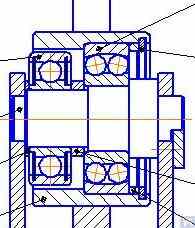
Fig. 3.16. Example of Roller Supporting Assembly Design with Two Rolling Bearings
ภาพที่ 3.17 แสดงแบบการออกแบบของชุดรองรับลูกกลิ้งแบบปรับแนวได้เอง ซึ่งพัฒนาโดยผู้เชี่ยวชาญของบริษัท "Technobalance" ในการออกแบบนี้ ความสามารถในการปรับแนวได้เองของลูกกลิ้งเกิดขึ้นจากการเพิ่มองศาอิสระอีกสององศา ทำให้ลูกกลิ้งสามารถเคลื่อนที่เชิงมุมเล็กๆ รอบแกน X และ Y ได้ ชุดรองรับดังกล่าวช่วยให้มั่นใจได้ถึงความแม่นยำสูงในการติดตั้งโรเตอร์ที่สมดุล และมักแนะนำให้ใช้กับแท่นรองรับของเครื่องปรับสมดุลขนาดใหญ่.

Fig. 3.17. Example of Self-Aligning Roller Supporting Assembly Design
As mentioned earlier, roller support assemblies typically have fairly high requirements for precision manufacturing and rigidity. In particular, the tolerances set for radial runout of the rollers should not exceed 3-5 microns.
ในทางปฏิบัติ แม้แต่ผู้ผลิตที่มีชื่อเสียงก็ยังไม่สามารถทำได้ตามมาตรฐานนี้เสมอไป ตัวอย่างเช่น ในระหว่างการทดสอบการเบี่ยงเบนในแนวรัศมีของชุดลูกกลิ้งรองรับใหม่ที่ซื้อมาเป็นอะไหล่สำหรับเครื่องปรับสมดุลรุ่น H8V ยี่ห้อ "K. Shenk" พบว่าการเบี่ยงเบนในแนวรัศมีของลูกกลิ้งมีค่าสูงถึง 10-11 ไมครอน.
3.2.1.3. Spindle Supporting Assemblies
When balancing rotors with flange mounting (for example, cardan shafts) on balancing machines, spindles are used as supporting assemblies for positioning, mounting, and rotation of the balanced products.
Spindles are one of the most complex and critical components of balancing machines, largely responsible for achieving the required balancing quality.
ทฤษฎีและการปฏิบัติในการออกแบบและการผลิตแกนหมุนได้รับการพัฒนาอย่างดีและสะท้อนให้เห็นในสิ่งพิมพ์หลากหลายประเภท ซึ่งในจำนวนนี้ เอกสารทางวิชาการเรื่อง "รายละเอียดและกลไกของเครื่องมือตัดโลหะ" [1] ซึ่งแก้ไขโดย ดร. วิศวกร DN Reshetov ถือเป็นเอกสารที่มีประโยชน์และเข้าถึงได้ง่ายที่สุดสำหรับนักพัฒนา.
Among the main requirements that should be considered in the design and manufacturing of balancing machine spindles, the following should be prioritized:
a) Providing high rigidity of the spindle assembly structure sufficient to prevent unacceptable deformations that may occur under the influence of unbalance forces of the balanced rotor;
b) Ensuring the stability of the spindle rotation axis position, characterized by permissible values of radial, axial, and axial runouts of the spindle;
c) Ensuring proper wear resistance of the spindle journals, as well as its seating and supporting surfaces used for mounting balanced products.
การนำข้อกำหนดเหล่านี้ไปใช้ในทางปฏิบัติมีรายละเอียดอยู่ในส่วนที่ VI "แกนหมุนและส่วนรองรับ" ของงาน [1].
In particular, there are methodologies for verifying the rigidity and rotational accuracy of spindles, recommendations for selecting bearings, choosing spindle material and methods of its hardening, as well as much other useful information on this topic.
Work [1] notes that in the design of spindles for most types of metal-cutting machine tools, a two-bearing scheme is mainly used.
An example of the design variant of such a two-bearing scheme used in milling machine spindles (details can be found in work [1]) is shown in Fig. 3.18.
This scheme is quite suitable for the manufacture of balancing machine spindles, examples of design variants of which are shown below in Figures 3.19-3.22.

Fig. 3.18. Sketch of a Two-Bearing Milling Machine Spindle
Figure 3.19 shows one of the design variants of the leading spindle assembly of a balancing machine, rotating on two radial-thrust bearings, each of which has its own independent housing 1 and 2. A flange 4, intended for flange mounting of a cardan shaft, and a pulley 5, used to transmit rotation to the spindle from the electric motor using a V-belt drive, are mounted on the spindle shaft 3.

Figure 3.19. Example of Spindle Design on Two Independent Bearing Supports
Figures 3.20 and 3.21 show two closely related designs of leading spindle assemblies. In both cases, the spindle bearings are installed in a common housing 1, which has a through axial hole necessary for installing the spindle shaft. At the entrance and exit of this hole, the housing has special bores (not shown in the figures), designed to accommodate radial thrust bearings (roller or ball) and special flange covers 5, used to secure the outer rings of the bearings.

Figure 3.20. Example 1 of a Leading Spindle Design on Two Bearing Supports Installed in a Common Housing

Figure 3.21. Example 2 of a Leading Spindle Design on Two Bearing Supports Installed in a Common Housing
As in the previous version (see Fig. 3.19), a faceplate 2 is installed on the spindle shaft, intended for flange mounting of the drive shaft, and a pulley 3, used to transmit rotation to the spindle from the electric motor via a belt drive. A limb 4 is also fixed to the spindle shaft, which is used to determine the angular position of the spindle, utilized when installing test and corrective weights on the rotor during balancing.

Figure 3.22. Example of a Design of a Driven (Rear) Spindle
Figure 3.22 shows a design variant of the driven (rear) spindle assembly of a machine, which differs from the leading spindle only by the absence of the drive pulley and limb, as they are not needed.

รูปที่ 3.23 ตัวอย่างการออกแบบและการใช้งานจริงของแกนหมุนขับเคลื่อน (ด้านหลัง)
As seen in Figures 3.20 – 3.22, the spindle assemblies discussed above are attached to the Soft Bearing supports of balancing machines using special clamps (straps) 6. Other methods of attachment can also be used if necessary, ensuring proper rigidity and precision in positioning the spindle assembly on the support.
Figure 3.23 illustrates a design of flange mounting similar to that spindle, which can be used for its installation on a Hard Bearing support of a balancing machine.
3.2.1.3.4 การคำนวณค่าความแข็งของแกนหมุนและการเบี่ยงเบนในแนวรัศมี
ในการกำหนดความแข็งแกร่งของแกนหมุนและการเบี่ยงเบนรัศมีที่คาดการณ์ไว้ สามารถใช้สูตร 3.4 ได้ (ดูแผนผังการคำนวณในรูปที่ 3.24):
where:
- Y - ระยะการเคลื่อนที่แบบยืดหยุ่นของแกนหมุนที่ปลายคอนโซลแกนหมุน หน่วยเป็นเซนติเมตร;
- P - แรงที่คำนวณได้ซึ่งกระทำต่อคอนโซลแกนหมุน (กิโลกรัม);
- ก - ตัวรองรับแบริ่งด้านหลังของแกนหมุน;
- B - ฐานรองตลับลูกปืนด้านหน้าของแกนหมุน;
- ก - ความยาวของคอนโซลแกนหมุน (ซม.);
- ค - ระยะห่างระหว่างจุดรองรับ A และ B ของแกนหมุน หน่วยเป็นเซนติเมตร;
- เจ1 - ค่าโมเมนต์ความเฉื่อยเฉลี่ยของส่วนแกนหมุนระหว่างจุดรองรับ หน่วยเป็น cm⁴;
- เจ2 - ค่าโมเมนต์ความเฉื่อยเฉลี่ยของส่วนคอนโซลแกนหมุน หน่วยเป็น cm⁴;
- เจบีและเจเอ - ค่าความแข็งของแบริ่งสำหรับส่วนรองรับด้านหน้าและด้านหลังของแกนหมุน ตามลำดับ หน่วยเป็น กก./ซม.
โดยการแปลงสูตร 3.4 ค่าที่คำนวณได้ของความแข็งของชุดแกนหมุนที่ต้องการ จชป สามารถกำหนดได้:
เมื่อพิจารณาคำแนะนำในการทำงาน [1] สำหรับเครื่องปรับสมดุลขนาดกลาง ค่านี้ไม่ควรต่ำกว่า 50 กก./µm
สำหรับการคำนวณค่าความคลาดเคลื่อนในแนวรัศมี จะใช้สูตร 3.5:
where:
- ∆ คือค่ารันเอาท์ในแนวรัศมีที่ปลายคอนโซลสปินเดิล, µm;
- ∆B คือความเบี่ยงเบนหนีศูนย์ในแนวรัศมีของแบริ่งสปินเดิลด้านหน้า, µm;
- ∆A คือความเบี่ยงเบนหนีศูนย์ในแนวรัศมีของแบริ่งสปินเดิลด้านหลัง, µm;
- g คือความยาวของคอนโซลแกนหมุน cm;
- c คือระยะห่างระหว่างส่วนรองรับ A และ B ของแกนหมุน cm
3.2.1.3.5. การรับรองข้อกำหนดด้านความสมดุลของสปินเดิล
ชุดแกนหมุนของเครื่องปรับสมดุลต้องได้รับการปรับสมดุลอย่างดี เนื่องจากความไม่สมดุลใดๆ จะส่งผลต่อโรเตอร์ที่กำลังปรับสมดุลอยู่ ทำให้เกิดข้อผิดพลาดเพิ่มเติม เมื่อกำหนดค่าความคลาดเคลื่อนทางเทคโนโลยีสำหรับความไม่สมดุลที่เหลืออยู่ของแกนหมุน โดยทั่วไปแล้วแนะนำให้ระดับความแม่นยำของการปรับสมดุลสูงกว่าระดับความแม่นยำของผลิตภัณฑ์ที่กำลังปรับสมดุลบนเครื่องอย่างน้อย 1-2 ระดับ.
เมื่อพิจารณาถึงคุณสมบัติการออกแบบของสปินเดิลที่กล่าวถึงข้างต้น การปรับสมดุลควรทำในสองระนาบ
3.2.1.3.6. รับประกันความสามารถในการรับน้ำหนักของตลับลูกปืนและข้อกำหนดด้านความทนทานสำหรับตลับลูกปืนแกนหมุน
เมื่อออกแบบแกนหมุนและเลือกขนาดตลับลูกปืน ควรประเมินความทนทานและความสามารถในการรับน้ำหนักของตลับลูกปืนเบื้องต้น วิธีการคำนวณเหล่านี้มีรายละเอียดอยู่ใน ISO 18855-94 (ISO 281-89) "ตลับลูกปืนแบบหมุน - พิกัดรับน้ำหนักแบบไดนามิกและอายุการใช้งาน" [3] รวมถึงในคู่มือตลับลูกปืนแบบหมุนจำนวนมาก (รวมถึงแบบดิจิทัล).
3.2.1.3.7. การรับรองข้อกำหนดสำหรับการทำความร้อนที่ยอมรับได้ของตลับลูกปืนแกนหมุน
ตามคำแนะนำจากงาน [1] ความร้อนสูงสุดที่อนุญาตของวงแหวนด้านนอกของแบริ่งแกนหมุนไม่ควรเกิน 70°C อย่างไรก็ตาม เพื่อให้มั่นใจถึงความสมดุลคุณภาพสูง การทำความร้อนที่แนะนำของวงแหวนด้านนอกไม่ควรเกิน 40 – 45°C
3.2.1.3.8. การเลือกประเภทของสายพานขับและการออกแบบรอกขับสำหรับสปินเดิล
เมื่อออกแบบแกนหมุนของเครื่องปรับสมดุล แนะนำให้ตรวจสอบให้แน่ใจว่าหมุนได้โดยใช้ระบบขับเคลื่อนสายพานแบน ตัวอย่างของการใช้ไดรฟ์สำหรับการทำงานของแกนหมุนอย่างเหมาะสมแสดงไว้ใน รูปที่ 3.20 และ 3.23. การใช้สายพานตัววีหรือสายพานฟันเฟืองนั้นไม่เหมาะสม เนื่องจากอาจทำให้เกิดภาระไดนามิกเพิ่มเติมต่อแกนหมุนอันเนื่องมาจากความไม่แม่นยำทางเรขาคณิตของสายพานและรอก ซึ่งอาจนำไปสู่ข้อผิดพลาดในการวัดเพิ่มเติมในระหว่างการปรับสมดุล ข้อกำหนดที่แนะนำสำหรับรอกสำหรับสายพานขับแบบแบนมีระบุไว้ใน ISO 17383-73 "รอกสำหรับสายพานขับแบบแบน" [4].
รอกขับควรอยู่ในตำแหน่งที่ปลายด้านหลังของสปินเดิล ใกล้กับชุดแบริ่งมากที่สุด (โดยมีส่วนยื่นน้อยที่สุด) การตัดสินใจออกแบบสำหรับการวางตำแหน่งรอกที่ยื่นออกมา ซึ่งทำขึ้นในการผลิตแกนหมุนดังที่แสดงไว้ใน รูปที่ 3.19ถือว่าไม่สำเร็จเนื่องจากจะเพิ่มโมเมนต์ของโหลดไดนามิกไดรฟ์ที่ทำงานบนแกนรองรับอย่างมีนัยสำคัญ
ข้อเสียเปรียบที่สำคัญอีกประการหนึ่งของการออกแบบนี้คือการใช้สายพานร่องวี ความไม่ถูกต้องในการผลิตและการประกอบซึ่งอาจเป็นสาเหตุของภาระเพิ่มเติมที่ไม่พึงประสงค์บนแกนหมุน
3.3. เตียง (โครง)
เบดเป็นโครงสร้างรองรับหลักของเครื่องปรับสมดุล ซึ่งมีองค์ประกอบหลักเป็นพื้นฐาน รวมถึงเสารองรับและมอเตอร์ขับเคลื่อน เมื่อเลือกหรือผลิตกระบะของเครื่องปรับสมดุล จำเป็นต้องตรวจสอบให้แน่ใจว่าเป็นไปตามข้อกำหนดหลายประการ รวมถึงความแข็งที่จำเป็น ความแม่นยำทางเรขาคณิต ความต้านทานการสั่นสะเทือน และความต้านทานการสึกหรอของตัวนำ
การปฏิบัติแสดงให้เห็นว่าเมื่อผลิตเครื่องจักรตามความต้องการของตนเอง ตัวเลือกเตียงต่อไปนี้มักใช้กันมากที่สุด:
- เตียงเหล็กหล่อจากเครื่องตัดโลหะที่ใช้แล้ว (เครื่องกลึง งานไม้ ฯลฯ)
- ประกอบเตียงตามช่องประกอบโดยใช้ข้อต่อแบบสลักเกลียว
- เตียงเชื่อมตามช่อง
- เตียงคอนกรีตโพลีเมอร์พร้อมสารเคลือบดูดซับแรงสั่นสะเทือน

รูปที่ 3.25. ตัวอย่างการใช้เตียงเครื่องจักรงานไม้มือสองเพื่อผลิตเครื่องจักรสำหรับปรับสมดุลเพลาคาร์ดาน
3.4. ไดรฟ์สำหรับเครื่องปรับสมดุล
จากการวิเคราะห์โซลูชันการออกแบบที่ลูกค้าของเราใช้ในการผลิตเครื่องจักรปรับสมดุล พบว่าส่วนใหญ่มุ่งเน้นไปที่การใช้มอเตอร์ AC ที่ติดตั้งไดรฟ์ความถี่แปรผันในระหว่างการออกแบบไดรฟ์ วิธีการนี้ช่วยให้สามารถปรับความเร็วในการหมุนได้หลากหลายสำหรับโรเตอร์ที่สมดุลโดยมีต้นทุนน้อยที่สุด กำลังของมอเตอร์ขับเคลื่อนหลักที่ใช้ในการหมุนโรเตอร์ที่สมดุลมักจะเลือกตามมวลของโรเตอร์เหล่านี้ และอาจประมาณได้:
- 0.25 - 0.72 กิโลวัตต์ สำหรับเครื่องจักรที่ออกแบบมาเพื่อปรับสมดุลโรเตอร์ที่มีมวล ≤ 5 กิโลกรัม;
- 0.72 - 1.2 กิโลวัตต์ สำหรับเครื่องจักรที่ออกแบบมาเพื่อปรับสมดุลโรเตอร์ที่มีมวล > 5 ≤ 50 กิโลกรัม;
- 1.2 - 1.5 กิโลวัตต์ สำหรับเครื่องจักรที่ออกแบบมาเพื่อปรับสมดุลโรเตอร์ที่มีมวล > 50 ≤ 100 กิโลกรัม;
- 1.5 - 2.2 กิโลวัตต์ สำหรับเครื่องจักรที่ออกแบบมาเพื่อปรับสมดุลโรเตอร์ที่มีมวล > 100 ≤ 500 กิโลกรัม;
- 2.2 - 5 กิโลวัตต์ สำหรับเครื่องจักรที่ออกแบบมาเพื่อปรับสมดุลโรเตอร์ที่มีมวล > 500 ≤ 1000 กิโลกรัม;
- 5 - 7.5 กิโลวัตต์ สำหรับเครื่องจักรที่ออกแบบมาเพื่อปรับสมดุลโรเตอร์ที่มีมวล > 1000 ≤ 3000 กิโลกรัม.
มอเตอร์เหล่านี้ควรติดตั้งอย่างแน่นหนาบนเตียงเครื่องจักรหรือฐานราก ก่อนการติดตั้งบนเครื่องจักร (หรือที่สถานที่ติดตั้ง) มอเตอร์ขับเคลื่อนหลักพร้อมกับรอกที่ติดตั้งบนเพลาเอาท์พุต ควรมีการปรับสมดุลอย่างระมัดระวัง เพื่อลดการรบกวนทางแม่เหล็กไฟฟ้าที่เกิดจากตัวแปลงความถี่ ขอแนะนำให้ติดตั้งตัวกรองเครือข่ายที่อินพุตและเอาต์พุต สิ่งเหล่านี้อาจเป็นผลิตภัณฑ์มาตรฐานที่มีจำหน่ายทั่วไปโดยผู้ผลิตไดรฟ์หรือตัวกรองแบบโฮมเมดที่ผลิตโดยใช้วงแหวนเฟอร์ไรต์
4. Measuring Systems of Balancing Machines
ผู้ผลิตเครื่องปรับสมดุลสมัครเล่นส่วนใหญ่ที่ติดต่อบริษัท "Kinematics" (Vibromera) วางแผนที่จะใช้ระบบวัดซีรีส์ "Balanset" ที่ผลิตโดยบริษัทของเราในการออกแบบของพวกเขา อย่างไรก็ตาม ยังมีลูกค้าบางรายที่วางแผนจะผลิตระบบวัดดังกล่าวด้วยตนเอง ดังนั้นจึงควรที่จะหารือเกี่ยวกับการสร้างระบบวัดสำหรับเครื่องปรับสมดุลในรายละเอียดเพิ่มเติม ข้อกำหนดหลักสำหรับระบบเหล่านี้คือความต้องการการวัดค่าแอมพลิจูดและเฟสของส่วนประกอบการหมุนของสัญญาณการสั่นสะเทือนที่มีความแม่นยำสูง ซึ่งปรากฏขึ้นที่ความถี่การหมุนของโรเตอร์ที่ปรับสมดุลแล้ว เป้าหมายนี้มักจะบรรลุได้โดยการใช้โซลูชันทางเทคนิคหลายอย่างร่วมกัน ซึ่งรวมถึง:
- Use of vibration sensors with a high signal conversion coefficient;
- Use of modern laser phase angle sensors;
- Creation (or use) of hardware that allows for the amplification and digital conversion of sensor signals (primary signal processing);
- การนำซอฟต์แวร์ประมวลผลสัญญาณการสั่นสะเทือนมาใช้ ซึ่งควรจะช่วยให้สามารถแยกส่วนประกอบการหมุนของสัญญาณการสั่นสะเทือนที่มีความละเอียดสูงและเสถียร โดยแสดงออกมาในรูปของความถี่การหมุนของโรเตอร์ที่สมดุล (การประมวลผลขั้นที่สอง).
ต่อไปนี้ เราจะพิจารณาถึงรูปแบบต่างๆ ของวิธีการแก้ปัญหาทางเทคนิคดังกล่าว ซึ่งถูกนำไปใช้ในเครื่องมือปรับสมดุลที่เป็นที่รู้จักกันดีหลายชนิด.
4.1. Selection of Vibration Sensors
In the measurement systems of balancing machines, various types of vibration sensors (transducers) can be used, including:
- Vibration acceleration sensors (accelerometers);
- Vibration velocity sensors;
- Vibration displacement sensors;
- Force sensors.
4.1.1. Vibration Acceleration Sensors
ในบรรดาเซ็นเซอร์วัดความเร่งจากการสั่นสะเทือน เซ็นเซอร์แบบเพียโซและแบบคาปาซิทีฟ (ชิป) เป็นที่นิยมใช้กันอย่างแพร่หลาย ซึ่งสามารถใช้งานได้อย่างมีประสิทธิภาพในเครื่องปรับสมดุลแบบแบริ่งอ่อน ในทางปฏิบัติ โดยทั่วไปแล้ว อนุญาตให้ใช้เซ็นเซอร์วัดความเร่งจากการสั่นสะเทือนที่มีค่าสัมประสิทธิ์การแปลง (Kpr) อยู่ในช่วง 10 ถึง 30 mV/(m/s²) ได้ สำหรับเครื่องปรับสมดุลที่ต้องการความแม่นยำในการปรับสมดุลสูงเป็นพิเศษ แนะนำให้ใช้เซ็นเซอร์วัดความเร่งที่มีค่า Kpr สูงถึง 100 mV/(m/s²) ขึ้นไป ตัวอย่างเช่น เซ็นเซอร์วัดความเร่งแบบเพียโซรุ่น DN3M1 และ DN3M1V6 ที่ผลิตโดยบริษัท Izmeritel จำกัด สามารถใช้เป็นเซ็นเซอร์วัดการสั่นสะเทือนสำหรับเครื่องปรับสมดุลได้.
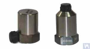
Figure 4.1. Piezo Accelerometers DN 3M1 and DN 3M1V6
To connect such sensors to vibration measuring instruments and systems, it is necessary to use external or built-in charge amplifiers.
รูปที่ 4.2. เครื่องวัดความเร่งแบบคาปาซิทีฟ AD1 ผลิตโดยบริษัท LLC "Kinematics" (Vibromera)
It should be noted that these sensors, which include widely used market boards of capacitive accelerometers ADXL 345 (see Figure 4.3), have several significant advantages over piezo accelerometers. Specifically, they are 4 to 8 times cheaper with similar technical characteristics. Moreover, they do not require the use of costly and finicky charge amplifiers needed for piezo accelerometers.
In cases where both types of accelerometers are used in the measurement systems of balancing machines, hardware integration (or double integration) of the sensor signals is usually performed.

Figure 4.2. Capacitive Accelerometers AD 1, assembled.
รูปที่ 4.2. เครื่องวัดความเร่งแบบคาปาซิทีฟ AD1 ผลิตโดยบริษัท LLC "Kinematics" (Vibromera)
It should be noted that these sensors, which include widely used market boards of capacitive accelerometers ADXL 345 (see Figure 4.3), have several significant advantages over piezo accelerometers. Specifically, they are 4 to 8 times cheaper with similar technical characteristics. Moreover, they do not require the use of costly and finicky charge amplifiers needed for piezo accelerometers.
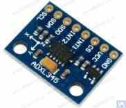
Figure 4.3. Capacitive accelerometer board ADXL 345.
In this case, the initial sensor signal, proportional to vibrational acceleration, is accordingly transformed into a signal proportional to vibrational velocity or displacement. The procedure of double integration of the vibration signal is particularly relevant when using accelerometers as part of the measuring systems for low-speed balancing machines, where the lower rotor rotation frequency range during balancing can reach 120 rpm and below. When using capacitive accelerometers in the measuring systems of balancing machines, it should be considered that after integration, their signals may contain low-frequency interference, manifesting in the frequency range from 0.5 to 3 Hz. This may limit the lower frequency range of balancing on machines intended to use these sensors.
4.1.2. Vibration Velocity Sensors
4.1.2.1. Inductive Vibration Velocity Sensors.
These sensors include an inductive coil and a magnetic core. When the coil vibrates relative to a stationary core (or the core relative to a stationary coil), an EMF is induced in the coil, the voltage of which is directly proportional to the vibration velocity of the movable element of the sensor. The conversion coefficients (Кпр) of inductive sensors are usually quite high, reaching several tens or even hundreds of mV/mm/sec. In particular, the conversion coefficient of the Schenck model T77 sensor is 80 mV/mm/sec, and for the IRD Mechanalysis model 544M sensor, it is 40 mV/mm/sec. In some cases (for example, in Schenck balancing machines), special highly sensitive inductive vibration velocity sensors with a mechanical amplifier are used, where Кпр can exceed 1000 mV/mm/sec. If inductive vibration velocity sensors are used in the measuring systems of balancing machines, hardware integration of the electrical signal proportional to vibration velocity can also be performed, converting it into a signal proportional to vibration displacement.
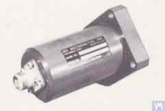
Figure 4.4. Model 544M sensor by IRD Mechanalysis.
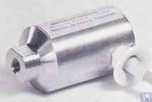
Figure 4.5. Model T77 sensor by Schenck
It should be noted that due to the labor intensity of their production, inductive vibration velocity sensors are quite scarce and expensive items. Therefore, despite the obvious advantages of these sensors, amateur manufacturers of balancing machines use them very rarely.
4.2. Phase Angle Sensors
เพื่อประสานกระบวนการวัดการสั่นสะเทือนกับมุมการหมุนของโรเตอร์ที่สมดุล จะใช้เซ็นเซอร์วัดมุมเฟส เช่น เซ็นเซอร์เลเซอร์ (โฟโตอิเล็กทริก) หรือเซ็นเซอร์แบบเหนี่ยวนำ เซ็นเซอร์เหล่านี้ผลิตขึ้นในรูปแบบต่างๆ โดยผู้ผลิตทั้งในและต่างประเทศ ช่วงราคาของเซ็นเซอร์เหล่านี้อาจแตกต่างกันอย่างมาก ตั้งแต่ประมาณ 40 ถึง 200 ดอลลาร์ ตัวอย่างของอุปกรณ์ดังกล่าวคือเซ็นเซอร์วัดมุมเฟสที่ผลิตโดย "Diamex" ดังแสดงในรูปที่ 4.11.

รูปที่ 4.11: เซ็นเซอร์วัดมุมเฟสจาก "Diamex""
ตัวอย่างเช่น รูปที่ 4.12 แสดงแบบจำลองที่บริษัท LLC "Kinematics" (Vibromera) นำมาใช้งาน ซึ่งใช้เครื่องวัดความเร็วรอบด้วยเลเซอร์รุ่น DT 2234C ที่ผลิตในประเทศจีนเป็นเซ็นเซอร์วัดมุมเฟส. The obvious advantages of this sensor include:
- A wide operating range, allowing measurement of rotor rotation frequency from 2.5 to 99,999 revolutions per minute, with a resolution of no less than one revolution;
- Digital display;
- Ease of setting up the tachometer for measurements;
- Affordability and low market cost;
- Relative simplicity of modification for integration into the measuring system of a balancing machine.

Figure 4.12: Laser Tachometer Model DT 2234C
ในบางกรณี เมื่อการใช้เซ็นเซอร์ออปติคอลเลเซอร์ไม่เป็นที่พึงปรารถนาไม่ว่าด้วยเหตุผลใดก็ตาม สามารถเปลี่ยนเซ็นเซอร์เหล่านี้ด้วยเซ็นเซอร์ดิสเพลสเมนต์เซนเซอร์แบบไม่สัมผัสแบบเหนี่ยวนำได้ เช่น รุ่น ISAN E41A ที่กล่าวถึงก่อนหน้านี้หรือผลิตภัณฑ์ที่คล้ายคลึงกันจากผู้ผลิตรายอื่น
4.3. คุณสมบัติการประมวลผลสัญญาณในเซ็นเซอร์สั่นสะเทือน
สำหรับการวัดแอมพลิจูดและเฟสที่แม่นยำของส่วนประกอบการหมุนของสัญญาณการสั่นสะเทือนในอุปกรณ์ปรับสมดุล โดยทั่วไปแล้วจะใช้เครื่องมือประมวลผลฮาร์ดแวร์และซอฟต์แวร์ร่วมกัน เครื่องมือเหล่านี้ช่วยให้:
- การกรองสัญญาณอนาล็อกของเซ็นเซอร์ด้วยฮาร์ดแวร์แบบบรอดแบนด์;
- การขยายสัญญาณอนาล็อกของเซ็นเซอร์;
- การรวมและ/หรือการรวมสองครั้ง (หากจำเป็น) ของสัญญาณอะนาล็อก
- การกรองสัญญาณแอนะล็อกแบบแคบโดยใช้ตัวกรองการติดตาม
- การแปลงสัญญาณอนาล็อกเป็นดิจิทัล
- การกรองสัญญาณดิจิตอลแบบซิงโครนัส
- การวิเคราะห์ฮาร์โมนิคของสัญญาณดิจิตอล
4.3.1. การกรองสัญญาณบรอดแบนด์
ขั้นตอนนี้นับว่าเป็นสิ่งจำเป็นสำหรับการทำความสะอาดสัญญาณเซ็นเซอร์การสั่นสะเทือนจากสัญญาณรบกวนที่อาจเกิดขึ้นได้ทั้งที่ขอบล่างและขอบบนของช่วงความถี่ของอุปกรณ์ ขอแนะนำให้ตั้งค่าขีดจำกัดล่างของตัวกรองแบบแบนด์พาสไว้ที่ 2-3 เฮิรตซ์ และขีดจำกัดบนไว้ที่ 50 (100) เฮิรตซ์ การกรอง "ล่าง" ช่วยลดสัญญาณรบกวนความถี่ต่ำที่อาจปรากฏที่เอาต์พุตของตัวขยายสัญญาณวัดเซ็นเซอร์ประเภทต่างๆ การกรอง "บน" ช่วยขจัดความเป็นไปได้ของสัญญาณรบกวนเนื่องจากความถี่ผสมและการสั่นสะเทือนแบบเรโซแนนซ์ที่อาจเกิดขึ้นของชิ้นส่วนกลไกแต่ละชิ้นของเครื่องจักร.
4.3.2. การขยายสัญญาณอนาล็อกจากเซนเซอร์
หากมีความจำเป็นต้องเพิ่มความไวของระบบวัดของเครื่องปรับสมดุล สามารถขยายสัญญาณจากเซ็นเซอร์วัดการสั่นสะเทือนไปยังอินพุตของหน่วยวัดได้ ทั้งแอมพลิฟายเออร์มาตรฐานที่มีอัตราขยายคงที่และแอมพลิฟายเออร์แบบหลายขั้นตอนซึ่งสามารถเปลี่ยนอัตราขยายได้ตามระดับสัญญาณจริงจากเซ็นเซอร์ ตัวอย่างของแอมพลิฟายเออร์แบบหลายขั้นตอนที่ตั้งโปรแกรมได้ ได้แก่ แอมพลิฟายเออร์ที่ใช้ในตัวแปลงการวัดแรงดันไฟฟ้า เช่น E154 หรือ E14-140 จากบริษัท LLC "L-Card".
4.3.3. บูรณาการ
ตามที่ระบุไว้ก่อนหน้านี้ แนะนำให้ใช้การรวมฮาร์ดแวร์และ/หรือการรวมสัญญาณเซ็นเซอร์การสั่นสะเทือนสองครั้งในระบบการวัดของเครื่องจักรปรับสมดุล ดังนั้น สัญญาณมาตรความเร่งเริ่มต้น ซึ่งเป็นสัดส่วนกับการเร่งความเร็วของไวโบร สามารถแปลงเป็นสัญญาณที่เป็นสัดส่วนกับความเร็วไวโบร (การบูรณาการ) หรือการเคลื่อนที่ของไวโบร (การอินทิเกรตสองครั้ง) ในทำนองเดียวกัน สัญญาณเซ็นเซอร์ความเร็วไวโบรหลังการรวมเข้าด้วยกันสามารถเปลี่ยนเป็นสัญญาณตามสัดส่วนกับการกระจัดของไวโบรได้
4.3.4. การกรองย่านความถี่แคบของสัญญาณอะนาล็อกโดยใช้ตัวกรองการติดตาม
เพื่อลดการรบกวนและปรับปรุงคุณภาพการประมวลผลสัญญาณการสั่นสะเทือนในระบบการวัดของเครื่องปรับสมดุล สามารถใช้ตัวกรองติดตามแบบแถบความถี่แคบได้ ความถี่กลางของตัวกรองเหล่านี้จะถูกปรับโดยอัตโนมัติให้ตรงกับความถี่การหมุนของโรเตอร์ที่กำลังปรับสมดุลโดยใช้สัญญาณจากเซ็นเซอร์วัดการหมุนของโรเตอร์ วงจรรวมสมัยใหม่ เช่น MAX263, MAX264, MAX267, MAX268 จาก "MAXIM" สามารถนำมาใช้สร้างตัวกรองดังกล่าวได้.
4.3.5. การแปลงสัญญาณอนาล็อกเป็นดิจิทัล
การแปลงสัญญาณอนาล็อกเป็นดิจิทัลเป็นกระบวนการที่สำคัญอย่างยิ่ง ซึ่งช่วยให้สามารถปรับปรุงคุณภาพของการประมวลผลสัญญาณการสั่นสะเทือนในระหว่างการวัดแอมพลิจูดและเฟสได้ กระบวนการนี้ถูกนำไปใช้ในระบบการวัดเครื่องปรับสมดุลที่ทันสมัยทั้งหมด ตัวอย่างของการใช้งาน ADC ที่มีประสิทธิภาพ ได้แก่ ตัวแปลงสัญญาณวัดแรงดันไฟฟ้าชนิด E154 หรือ E14-140 จากบริษัท L-Card ซึ่งใช้ในระบบการวัดเครื่องปรับสมดุลหลายระบบที่ผลิตโดยบริษัท Kinematics (Vibromera) นอกจากนี้ บริษัท Kinematics (Vibromera) ยังมีประสบการณ์ในการใช้ระบบไมโครโปรเซสเซอร์ราคาประหยัดที่ใช้ตัวควบคุม Arduino, ไมโครคอนโทรลเลอร์ PIC18F4620 จากบริษัท Microchip และอุปกรณ์ที่คล้ายกัน.
4.1.2.2. เซ็นเซอร์วัดความเร็วการสั่นสะเทือนแบบใช้ตัวเร่งความเร็วเพียโซอิเล็กทริก
เซ็นเซอร์ประเภทนี้แตกต่างจากมาตรวัดความเร่งแบบเพียโซอิเล็กทริกมาตรฐานตรงที่มีตัวขยายสัญญาณและตัวรวมสัญญาณแบบฝังตัวอยู่ภายในตัวเรือน ซึ่งทำให้สามารถส่งสัญญาณที่แปรผันตามความเร็วการสั่นสะเทือนได้ ตัวอย่างเช่น เซ็นเซอร์วัดความเร็วการสั่นสะเทือนแบบเพียโซอิเล็กทริกที่ผลิตโดยผู้ผลิตในประเทศ (บริษัท ZETLAB และบริษัทจำกัด "Vibropribor") แสดงในรูปที่ 4.6 และ 4.7.
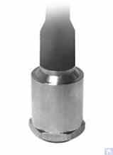
Figure 4.6. Model AV02 sensor by ZETLAB (Russia)

รูปที่ 4.7 เซ็นเซอร์รุ่น DVST 2 จากบริษัท LLC "Vibropribor""
Such sensors are manufactured by various producers (both domestic and foreign) and are currently widely used, especially in portable vibration equipment. The cost of these sensors is quite high and can reach 20,000 to 30,000 rubles each, even from domestic manufacturers.
4.1.3. Displacement Sensors
ในระบบการวัดของเครื่องปรับสมดุล สามารถใช้เซ็นเซอร์วัดระยะแบบไม่สัมผัส – ทั้งแบบคาปาซิทีฟหรือแบบเหนี่ยวนำ – ได้ เซ็นเซอร์เหล่านี้สามารถทำงานในโหมดคงที่ ทำให้สามารถบันทึกกระบวนการสั่นสะเทือนได้ตั้งแต่ 0 เฮิรตซ์ การใช้งานเซ็นเซอร์เหล่านี้จะมีประสิทธิภาพเป็นพิเศษในกรณีของการปรับสมดุลโรเตอร์ความเร็วต่ำที่มีความเร็วรอบ 120 รอบต่อนาทีหรือต่ำกว่า ค่าสัมประสิทธิ์การแปลงของเซ็นเซอร์เหล่านี้สามารถสูงถึง 1000 มิลลิโวลต์/มิลลิเมตร หรือสูงกว่า ซึ่งให้ความแม่นยำและความละเอียดสูงในการวัดระยะ แม้ว่าจะไม่มีการขยายสัญญาณเพิ่มเติม ข้อดีที่เห็นได้ชัดของเซ็นเซอร์เหล่านี้คือต้นทุนที่ค่อนข้างต่ำ ซึ่งสำหรับผู้ผลิตในประเทศบางรายนั้นไม่เกิน 1000 รูเบิล เมื่อใช้เซ็นเซอร์เหล่านี้ในเครื่องปรับสมดุล สิ่งสำคัญคือต้องพิจารณาว่าช่องว่างการทำงานที่กำหนดระหว่างองค์ประกอบที่ไวต่อการสัมผัสของเซ็นเซอร์กับพื้นผิวของวัตถุที่สั่นสะเทือนนั้นถูกจำกัดด้วยเส้นผ่านศูนย์กลางของขดลวดเซ็นเซอร์ ตัวอย่างเช่น สำหรับเซ็นเซอร์ที่แสดงในรูปที่ 4.8 รุ่น ISAN E41A จาก "TEKO" ช่องว่างการทำงานที่ระบุไว้โดยทั่วไปคือ 3.8 ถึง 4 มม. ซึ่งช่วยให้สามารถวัดการเคลื่อนที่ของวัตถุที่สั่นได้ในช่วง ±2.5 มม.
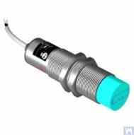
Figure 4.8. Inductive Displacement Sensor Model ISAN E41A by TEKO (Russia)
4.1.4. Force Sensors
As previously noted, force sensors are used in the measurement systems installed on Hard Bearing balancing machines. These sensors, particularly due to their simplicity of manufacture and relatively low cost, are commonly piezoelectric force sensors. Examples of such sensors are shown in Figures 4.9 and 4.10.

Figure 4.9. Force Sensor SD 1 by Kinematika LLC

รูปที่ 4.10: เซ็นเซอร์วัดแรงสำหรับเครื่องปรับสมดุลรถยนต์ จำหน่ายโดย "STO Market""
Strain gauge force sensors, which are manufactured by a wide range of domestic and foreign producers, can also be used to measure relative deformations in the supports of Hard Bearing balancing machines.
4.4 แผนผังการทำงานของระบบวัดของเครื่องปรับสมดุล "Balanset 2""
ระบบการวัด "Balanset 2" แสดงถึงแนวทางที่ทันสมัยในการบูรณาการฟังก์ชันการวัดและการคำนวณในเครื่องปรับสมดุล ระบบนี้คำนวณน้ำหนักแก้ไขโดยอัตโนมัติโดยใช้วิธีสัมประสิทธิ์อิทธิพล และสามารถปรับให้เข้ากับการกำหนดค่าเครื่องจักรต่างๆ ได้.
โครงสร้างการทำงานประกอบด้วยการปรับสภาพสัญญาณ การแปลงสัญญาณอนาล็อกเป็นดิจิทัล การประมวลผลสัญญาณดิจิทัล และอัลกอริธึมการคำนวณอัตโนมัติ ระบบนี้สามารถจัดการสถานการณ์การปรับสมดุลทั้งแบบสองระนาบและหลายระนาบได้อย่างแม่นยำสูง.
4.5. Calculation of Parameters of Correction Weights Used in Rotor Balancing
การคำนวณน้ำหนักปรับแก้จะใช้หลักการของสัมประสิทธิ์อิทธิพล ซึ่งจะกำหนดว่าโรเตอร์ตอบสนองต่อน้ำหนักทดสอบในระนาบต่างๆ อย่างไร วิธีนี้เป็นพื้นฐานของระบบปรับสมดุลสมัยใหม่ทั้งหมด และให้ผลลัพธ์ที่แม่นยำสำหรับทั้งโรเตอร์แบบแข็งและแบบยืดหยุ่น.
4.5.1. Task of Balancing Dual-support Rotors and Methods of its Resolution
สำหรับโรเตอร์แบบรองรับสองจุด (ซึ่งเป็นการกำหนดค่าที่พบได้บ่อยที่สุด) งานปรับสมดุลเกี่ยวข้องกับการกำหนดน้ำหนักแก้ไขสองค่า – ค่าหนึ่งสำหรับแต่ละระนาบการแก้ไข วิธีสัมประสิทธิ์อิทธิพลใช้วิธีการดังต่อไปนี้:
- การวัดครั้งแรก (รอบที่ 0): วัดการสั่นสะเทือนโดยไม่ต้องใช้ตุ้มน้ำหนักทดสอบ
- การทดลองวิ่งครั้งแรก (ครั้งที่ 1): เพิ่มน้ำหนักทดลองที่ทราบแล้วลงในระนาบที่ 1 แล้ววัดการตอบสนอง
- การทดลองวิ่งครั้งที่สอง (รอบที่ 2): ย้ายตุ้มน้ำหนักทดลองไปที่ระนาบที่ 2 แล้ววัดการตอบสนอง
- การคำนวณ: ซอฟต์แวร์จะคำนวณน้ำหนักการแก้ไขถาวรโดยอิงจากผลตอบสนองที่วัดได้
พื้นฐานทางคณิตศาสตร์เกี่ยวข้องกับการแก้ระบบสมการเชิงเส้นที่เชื่อมโยงอิทธิพลของน้ำหนักทดลองกับการแก้ไขที่จำเป็นในระนาบทั้งสองพร้อมกัน.
รูปที่ 3.26 และ 3.27 แสดงตัวอย่างการใช้เตียงกลึง ซึ่งมีการผลิตเครื่องจักร Hard Bearing เฉพาะสำหรับ balancing augers และเครื่องปรับสมดุล Soft Bearing สากลสำหรับโรเตอร์ทรงกระบอก สำหรับผู้ผลิต DIY โซลูชันดังกล่าวช่วยให้สามารถสร้างระบบรองรับที่แข็งแกร่งสำหรับเครื่องปรับสมดุลโดยใช้เวลาและต้นทุนน้อยที่สุด ซึ่งสามารถติดตั้งแท่นรองรับประเภทต่างๆ ได้ (ทั้งตลับลูกปืนแบบแข็งและตลับลูกปืนแบบอ่อน) งานหลักสำหรับผู้ผลิตในกรณีนี้คือเพื่อให้แน่ใจว่า (และเรียกคืนหากจำเป็น) ในความแม่นยำทางเรขาคณิตของรางนำเครื่องจักรซึ่งจะใช้ฐานรองรับ ในสภาวะการผลิตแบบ DIY มักใช้การขูดแบบละเอียดเพื่อคืนความแม่นยำทางเรขาคณิตที่ต้องการของไกด์
รูปที่ 3.28 แสดงให้เห็นรูปแบบเตียงที่ประกอบขึ้นจากสองช่อง ในการผลิตเตียงนี้ จะใช้การเชื่อมต่อแบบสลักเกลียวแบบถอดได้ ช่วยลดการเสียรูปของเตียงหรือกำจัดโดยสิ้นเชิงระหว่างการประกอบโดยไม่ต้องดำเนินการทางเทคโนโลยีเพิ่มเติม เพื่อให้แน่ใจว่ามีความแม่นยำทางเรขาคณิตของรางของเตียงที่ระบุ อาจจำเป็นต้องมีการประมวลผลทางกล (การบด การกัดแบบละเอียด) ของหน้าแปลนด้านบนของช่องที่ใช้
รูปที่ 3.29 และ 3.30 ปัจจุบันมีเตียงเชื่อมหลายแบบซึ่งทำจากสองช่องเช่นกัน เทคโนโลยีการผลิตสำหรับเตียงดังกล่าวอาจต้องมีการดำเนินการเพิ่มเติมหลายชุด เช่น การอบชุบด้วยความร้อน เพื่อบรรเทาความเครียดภายในที่เกิดขึ้นระหว่างการเชื่อม เช่นเดียวกับเตียงที่ประกอบขึ้น เพื่อให้แน่ใจว่ามีความแม่นยำทางเรขาคณิตของรางของเตียงที่เชื่อม ควรมีการวางแผนการประมวลผลทางกล (การบด การกัดแบบละเอียด) ของหน้าแปลนด้านบนของช่องที่ใช้
4.5.2. Methodology for Dynamic Balancing of Multi-support Rotors
โรเตอร์แบบหลายจุดรองรับ (สามหรือสี่จุดรองรับ) ต้องใช้ขั้นตอนการปรับสมดุลที่ซับซ้อนกว่า แต่ละจุดรองรับมีส่วนทำให้เกิดพฤติกรรมไดนามิกโดยรวม และการแก้ไขต้องคำนึงถึงปฏิสัมพันธ์ระหว่างระนาบทั้งหมดด้วย.
ระเบียบวิธีนี้เป็นการต่อยอดแนวทางการวิเคราะห์แบบสองระนาบโดย:
- วัดค่าการสั่นสะเทือนที่จุดรองรับทั้งหมด
- โดยใช้ตำแหน่งน้ำหนักทดลองหลายตำแหน่ง
- การแก้ระบบสมการเชิงเส้นขนาดใหญ่
- การปรับการกระจายน้ำหนักการแก้ไขให้เหมาะสมที่สุด
สำหรับเพลาคาร์ดานและโรเตอร์ยาวที่คล้ายกัน วิธีการนี้โดยทั่วไปจะทำให้ระดับความไม่สมดุลที่เหลืออยู่สอดคล้องกับเกรดคุณภาพ ISO G6.3 หรือดีกว่า.
4.5.3. Calculators for Balancing Multi-support Rotors
ได้มีการพัฒนาอัลกอริธึมการคำนวณเฉพาะทางสำหรับโครงสร้างโรเตอร์แบบสามฐานรองรับและสี่ฐานรองรับ เครื่องคำนวณเหล่านี้ถูกนำไปใช้ในซอฟต์แวร์ Balanset-4 และสามารถจัดการกับรูปทรงเรขาคณิตของโรเตอร์ที่ซับซ้อนได้โดยอัตโนมัติ.
เครื่องคิดเลขเหล่านี้คำนึงถึงสิ่งต่อไปนี้:
- ความแข็งของฐานรองรับที่เปลี่ยนแปลงได้
- การเชื่อมโยงข้ามระหว่างระนาบการแก้ไข
- การปรับตำแหน่งน้ำหนักให้เหมาะสมเพื่อความสะดวกในการเข้าถึง
- การตรวจสอบผลลัพธ์ที่คำนวณได้
5. Recommendations for Checking the Operation and Accuracy of Balancing Machines
ความแม่นยำและความน่าเชื่อถือของเครื่องปรับสมดุลขึ้นอยู่กับหลายปัจจัย รวมถึงความแม่นยำทางเรขาคณิตของชิ้นส่วนกลไก คุณลักษณะทางไดนามิกของแท่นรองรับ และความสามารถในการทำงานของระบบการวัด การตรวจสอบพารามิเตอร์เหล่านี้อย่างสม่ำเสมอช่วยให้มั่นใจได้ถึงคุณภาพการปรับสมดุลที่สม่ำเสมอและช่วยระบุปัญหาที่อาจเกิดขึ้นก่อนที่จะส่งผลกระทบต่อการผลิต.
5.1. Checking the Geometric Accuracy of the Machine
การตรวจสอบความถูกต้องทางเรขาคณิตประกอบด้วยการตรวจสอบการจัดแนวของตัวรองรับ ความขนานของตัวนำ และความเป็นศูนย์กลางของชุดแกนหมุน การตรวจสอบเหล่านี้ควรดำเนินการในระหว่างการตั้งค่าเริ่มต้นและเป็นระยะๆ ในระหว่างการใช้งานเพื่อให้มั่นใจได้ว่าความถูกต้องแม่นยำได้รับการรักษาไว้.
5.2. Checking the Dynamic Characteristics of the Machine
การตรวจสอบคุณลักษณะทางพลศาสตร์เกี่ยวข้องกับการวัดความถี่ธรรมชาติของส่วนรองรับและส่วนประกอบของโครงสร้างเพื่อให้แน่ใจว่าความถี่เหล่านั้นแยกออกจากความถี่ในการทำงานอย่างเหมาะสม ซึ่งจะช่วยป้องกันปัญหาการสั่นพ้องที่อาจส่งผลกระทบต่อความแม่นยำในการปรับสมดุล.
5.3. Checking the Operational Capability of the Measuring System
การตรวจสอบระบบการวัดประกอบด้วยการสอบเทียบเซ็นเซอร์ การตรวจสอบการจัดเรียงเฟส และการตรวจสอบความถูกต้องของการประมวลผลสัญญาณ ซึ่งช่วยให้มั่นใจได้ว่าการวัดความ amplitud และเฟสของการสั่นสะเทือนมีความน่าเชื่อถือที่ความเร็วในการทำงานทุกระดับ.
5.4 การตรวจสอบคุณลักษณะด้านความแม่นยำตามมาตรฐาน ISO 20076-2007
มาตรฐาน ISO 20076-2007 กำหนดขั้นตอนมาตรฐานสำหรับการตรวจสอบความแม่นยำของเครื่องปรับสมดุลโดยใช้โรเตอร์ทดสอบที่ได้รับการสอบเทียบ ขั้นตอนเหล่านี้ช่วยตรวจสอบความถูกต้องของประสิทธิภาพการทำงานของเครื่องจักรเทียบกับมาตรฐานที่เป็นที่ยอมรับในระดับสากล.
Literature
- Reshetov DN (บรรณาธิการ). "รายละเอียดและกลไกของเครื่องมือตัดโลหะ." มอสโก: Mashinostroenie, 1972.
- Kellenberger W. "การเจียรผิวทรงกระบอกด้วยเกลียว" เครื่องจักรกล, 1963.
- ISO 18855-94 (ISO 281-89) "ตลับลูกปืน - พิกัดรับน้ำหนักแบบไดนามิกและอายุการใช้งาน""
- ISO 17383-73 "รอกสำหรับสายพานขับแบบแบน""
- ISO 1940-1-2007 "การสั่นสะเทือน ข้อกำหนดสำหรับคุณภาพการทรงตัวของโรเตอร์แบบแข็ง""
- ISO 20076-2007 "ขั้นตอนการตรวจสอบความถูกต้องของเครื่องจักรปรับสมดุล""
Appendix 1: Algorithm for Calculating Parameters of Balancing for Three Support Shafts
การปรับสมดุลโรเตอร์แบบสามฐานรองรับจำเป็นต้องแก้ระบบสมการสามสมการที่มีตัวแปรไม่ทราบค่าสามตัว ภาคผนวกนี้ให้พื้นฐานทางคณิตศาสตร์และขั้นตอนการคำนวณทีละขั้นตอนสำหรับการกำหนดน้ำหนักแก้ไขในระนาบการแก้ไขทั้งสามระนาบ.
A1.1. พื้นฐานทางคณิตศาสตร์
สำหรับโรเตอร์แบบสามจุดรองรับ เมทริกซ์สัมประสิทธิ์อิทธิพลจะเชื่อมโยงผลกระทบของน้ำหนักทดลองกับการตอบสนองการสั่นสะเทือน ณ ตำแหน่งแบริ่งแต่ละจุด รูปแบบทั่วไปของระบบสมการมีดังนี้:
[V₂] = [A₂₁ A₂₂ A₂₃] [W₂]
[V₃] = [A₃₁ A₃₂ A₃₃] [W₃]
where:
- วี₁, วี₂, วี₃ - เวกเตอร์การสั่นสะเทือนที่จุดรองรับ 1, 2 และ 3
- W₁, W₂, W₃ - น้ำหนักแก้ไขในระนาบที่ 1, 2 และ 3
- Aᵢⱼ - สัมประสิทธิ์อิทธิพลที่เชื่อมโยงน้ำหนัก j กับการสั่นสะเทือนที่จุดรองรับ i
A1.2. ขั้นตอนการคำนวณ
- การวัดเบื้องต้น: บันทึกค่าแอมพลิจูดและเฟสของการสั่นสะเทือนที่จุดรองรับทั้งสามจุดโดยไม่ต้องใช้ตุ้มน้ำหนักทดลอง
- ลำดับน้ำหนักทดลอง: ใช้ตุ้มน้ำหนักทดสอบที่ทราบค่าแล้วกับระนาบการแก้ไขแต่ละระนาบตามลำดับ พร้อมบันทึกการเปลี่ยนแปลงของการสั่นสะเทือน
- การคำนวณค่าสัมประสิทธิ์อิทธิพล: ตรวจสอบว่าน้ำหนักทดลองแต่ละค่าส่งผลต่อการสั่นสะเทือนที่จุดรองรับแต่ละจุดอย่างไร
- วิธีแก้ปัญหาแบบเมทริกซ์: แก้ระบบสมการเพื่อหาค่าน้ำหนักการแก้ไขที่เหมาะสมที่สุด
- การจัดวางน้ำหนัก: ติดตั้งตุ้มน้ำหนักที่คำนวณไว้แล้วในมุมที่กำหนด
- การตรวจสอบ: ตรวจสอบว่าค่าการสั่นสะเทือนที่เหลืออยู่เป็นไปตามข้อกำหนด
A1.3. ข้อควรพิจารณาพิเศษสำหรับโรเตอร์แบบสามฐานรองรับ
โครงสร้างแบบสามจุดรองรับมักใช้กับเพลาคาร์ดานยาวที่ต้องการจุดรองรับตรงกลางเพื่อป้องกันการโก่งตัวมากเกินไป ข้อควรพิจารณาที่สำคัญ ได้แก่:
- ความแข็งแกร่งของฐานรองรับระดับกลางส่งผลต่อพลศาสตร์โดยรวมของโรเตอร์
- การจัดแนวการรองรับมีความสำคัญอย่างยิ่งต่อผลลัพธ์ที่แม่นยำ
- ขนาดของน้ำหนักทดลองต้องทำให้เกิดการตอบสนองที่วัดได้ที่จุดรองรับทั้งหมด
- การเชื่อมโยงข้ามระหว่างระนาบต่างๆ จำเป็นต้องได้รับการวิเคราะห์อย่างรอบคอบ
Appendix 2: Algorithm for Calculating Parameters of Balancing for Four Support Shafts
การปรับสมดุลโรเตอร์แบบสี่จุดรองรับถือเป็นรูปแบบที่ซับซ้อนที่สุดที่พบได้ทั่วไป โดยต้องใช้การแก้ปัญหาระบบเมทริกซ์ 4x4 รูปแบบนี้มักใช้กับโรเตอร์ที่มีความยาวมาก เช่น ลูกกลิ้งในโรงงานกระดาษ เพลาเครื่องจักรสิ่งทอ และโรเตอร์อุตสาหกรรมหนัก.
A2.1. แบบจำลองทางคณิตศาสตร์แบบขยาย
ระบบรองรับสี่จุดเป็นการต่อยอดจากแบบจำลองรองรับสามจุด โดยเพิ่มสมการเพิ่มเติมเพื่อพิจารณาตำแหน่งแบริ่งที่สี่:
[V₂] = [A₂₁ A₂₂ A₂₃ A₂₄] [W₂]
[V₃] = [A₃₁ A₃₂ A₃₃ A₃₄] [W₃]
[V₄] = [A₄₁ A₄₂ A₄₃ A₄₄] [W₄]
A2.2. ขั้นตอนการชั่งน้ำหนักทดลองแบบต่อเนื่อง
ขั้นตอนการทดสอบโดยใช้ฐานรองรับสี่จุดต้องทำการวัดทั้งหมดห้ารอบ:
- การทดลองครั้งที่ 0: การวัดเบื้องต้นที่จุดรองรับทั้งสี่จุด
- วิ่ง 1: ทดสอบน้ำหนักในระนาบที่ 1 วัดจุดรองรับทั้งหมด
- รอบที่ 2: ทดสอบน้ำหนักในระนาบที่ 2 วัดจุดรองรับทั้งหมด
- รอบที่ 3: ทดสอบน้ำหนักในระนาบที่ 3 วัดจุดรองรับทั้งหมด
- รอบที่ 4: ทดสอบน้ำหนักในระนาบที่ 4 วัดจุดรองรับทั้งหมด
A2.3. ข้อควรพิจารณาในการปรับปรุงให้เหมาะสม
การปรับสมดุลด้วยจุดรองรับทั้งสี่มักทำให้ได้คำตอบที่ถูกต้องหลายคำตอบ กระบวนการเพิ่มประสิทธิภาพจะพิจารณาถึง:
- ลดมวลรวมในการแก้ไขให้เหลือน้อยที่สุด
- การตรวจสอบให้แน่ใจว่ามีตำแหน่งวางน้ำหนักที่เข้าถึงได้ง่าย
- การสร้างสมดุลระหว่างค่าความคลาดเคลื่อนในการผลิตและต้นทุน
- เป็นไปตามขีดจำกัดการสั่นสะเทือนตกค้างที่กำหนดไว้
Appendix 3: Guide to Using the Balancer Calculator
เครื่องคำนวณปรับสมดุล Balanset จะทำการคำนวณทางคณิตศาสตร์ที่ซับซ้อนซึ่งอธิบายไว้ในภาคผนวก 1 และ 2 โดยอัตโนมัติ คู่มือนี้ให้คำแนะนำเชิงปฏิบัติสำหรับการใช้เครื่องคำนวณอย่างมีประสิทธิภาพกับเครื่องปรับสมดุลแบบทำเอง.
A3.1. การติดตั้งและกำหนดค่าซอฟต์แวร์
- คำจำกัดความของเครื่องจักร: กำหนดรูปทรงเรขาคณิตของเครื่องจักร ตำแหน่งการรองรับ และระนาบการแก้ไข
- การปรับเทียบเซ็นเซอร์: ตรวจสอบทิศทางของเซ็นเซอร์และปัจจัยการสอบเทียบ
- การเตรียมน้ำหนักทดลอง: คำนวณมวลน้ำหนักทดลองที่เหมาะสมโดยพิจารณาจากคุณลักษณะของโรเตอร์
- การตรวจสอบความปลอดภัย: ตรวจสอบความเร็วในการใช้งานที่ปลอดภัยและวิธีการติดตั้งน้ำหนักให้ถูกต้อง
A3.2. ลำดับการวัด
เครื่องคำนวณจะแนะนำผู้ใช้ตลอดลำดับการวัด พร้อมให้ข้อมูลป้อนกลับแบบเรียลไทม์เกี่ยวกับคุณภาพการวัด และข้อเสนอแนะสำหรับการปรับปรุงอัตราส่วนสัญญาณต่อสัญญาณรบกวน.
A3.3 การตีความผลลัพธ์
เครื่องคิดเลขนี้รองรับรูปแบบผลลัพธ์หลายรูปแบบ:
- การแสดงผลเวกเตอร์กราฟิกที่แสดงข้อกำหนดในการแก้ไข
- ข้อมูลจำเพาะเชิงตัวเลขของน้ำหนักและมุม
- ตัวชี้วัดคุณภาพและดัชนีความเชื่อมั่น
- ข้อเสนอแนะเพื่อปรับปรุงความแม่นยำในการวัด
A3.4. การแก้ไขปัญหาทั่วไป
ปัญหาและวิธีแก้ไขที่พบบ่อยเมื่อใช้เครื่องคิดเลขกับเครื่องจักร DIY:
- การตอบสนองต่อน้ำหนักทดลองไม่เพียงพอ: เพิ่มน้ำหนักในการทดลองหรือตรวจสอบการติดตั้งเซ็นเซอร์
- การวัดที่ไม่สอดคล้องกัน: ตรวจสอบความสมบูรณ์ทางกลไก ตรวจสอบสภาวะการสั่นสะเทือน
- ผลการแก้ไขที่ไม่ดี: ตรวจสอบความถูกต้องของการวัดมุม และตรวจสอบผลกระทบจากการเชื่อมโยงข้าม (cross-coupling effects)
- ข้อผิดพลาดของซอฟต์แวร์: ตรวจสอบการเชื่อมต่อเซ็นเซอร์ ตรวจสอบพารามิเตอร์อินพุต และตรวจสอบให้แน่ใจว่ารอบต่อนาที (RPM) คงที่
ผู้เขียนบทความ: เฟลด์แมน วาเลรี ดาวิโดวิช
บรรณาธิการและผู้แปล: นิโคไล อันดรีวิช เชลโคเวนโก
ฉันขอโทษสำหรับข้อผิดพลาดในการแปลที่อาจเกิดขึ้น


