


3. Requirements for the Construction of Basic Units and Mechanisms of Balancing Machines 3.1. Bearings 3.1.1. Theoretical Foundations of Bearing Design
In the previous section, the main design executions of Soft Bearing and Hard Bearing supports for balancing machines were discussed in detail. A crucial parameter that designers must consider when designing and manufacturing these supports is their natural frequencies of oscillation. This is important because the measurement of not only the amplitude of vibration (cyclic deformation) of the supports but also the phase of vibration is required for calculating the parameters of corrective weights by the machine’s measuring and computing systems.
If the natural frequency of a support coincides with the rotation frequency of the balanced rotor (support resonance), accurate measurement of amplitude and phase of vibration is practically impossible. This is clearly illustrated in the graphs showing changes in amplitude and phase of the support’s oscillations as a function of the rotational frequency of the balanced rotor (see Fig. 3.1).
From these graphs, it follows that as the rotational frequency of the balanced rotor approaches the natural frequency of the support oscillations (i.e., when the ratio fp/fo is close to 1), there is a significant increase in amplitude associated with the resonance oscillations of the support (see Fig. 3.1.a). Simultaneously, graph 3.1.b shows that in the resonance zone, there is a sharp change in the phase angle ∆F°, which can reach up to 180°.
In other words, when balancing any mechanism in the resonance zone, even small changes in its rotation frequency can lead to significant instability in the measurement results of amplitude and phase of its vibration, leading to errors in calculating the parameters of corrective weights and negatively affecting the quality of balancing.
The above graphs confirm earlier recommendations that for Hard Bearing machines, the upper limit of the rotor’s operational frequencies should be (at least) 2-3 times lower than the natural frequency of the support, fo. For Soft Bearing machines, the lower limit of permissible operational frequencies of the balanced rotor should (at least) be 2-3 times higher than the natural frequency of the support.
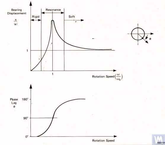
Figure 3.1. Graphs showing changes in relative amplitude and phase of vibrations of the balancing machine support as a function of rotational frequency changes.
Given the information presented, operating the machine in the resonance area of its supports (highlighted in red in Fig. 3.1) is not recommended. The graphs shown in Fig. 3.1 also demonstrate that for the same imbalances of the rotor, the actual vibrations of the Soft Bearing machine supports are significantly lower than those occurring on the Soft Bearing machine supports.
From this, it follows that sensors used to measure vibrations of supports in Hard Bearing machines must have higher sensitivity than those in Soft Bearing machines. This conclusion is well supported by the actual practice of using sensors, which shows that absolute vibration sensors (vibro-accelerometers and/or vibro-velocity sensors), successfully used in Soft Bearing balancing machines, often cannot achieve the necessary balancing quality on Hard Bearing machines.
On these machines, it is recommended to use relative vibration sensors, such as force sensors or highly sensitive displacement sensors.
3.1.2. Estimating Natural Frequencies of Supports Using Calculation Methods
A designer can perform an approximate (estimative) calculation of the natural frequency of a support fo using formula 3.1, by simplistically treating it as a vibrational system with one degree of freedom, which (see Fig. 2.19.a) is represented by a mass M, oscillating on a spring with stiffness K.
fo=2π1MK(3.1)
The mass M used in the calculation for a symmetric inter-bearing rotor can be approximated by formula 3.2.
M=Mo+nMr(3.2) where Mo is the mass of the moving part of the support in kg; Mr is the mass of the balanced rotor in kg; n is the number of machine supports involved in the balancing.
The stiffness K of the support is calculated using formula 3.3 based on the results of experimental studies that involve measuring the deformation ΔL of the support when it is loaded with a static force P (see Figs. 3.2.a and 3.2.b).
K=ΔLP(3.3) where ΔL is the deformation of the support in meters; P is the static force in Newtons.
The magnitude of the loading force P can be measured using a force-measuring instrument (e.g., a dynamometer). The displacement of the support ΔL is determined using a device for measuring linear displacements (e.g., a dial indicator).
3. Requirements for the Construction of Basic Units and Mechanisms of Balancing Machines 3.1. Bearings 3.1.2. Calculating Natural Frequencies of Supports by Computational Methods
Calculations of the natural frequencies of supports using the above-discussed calculation scheme can be performed in two directions:
Calculating the natural frequencies of supports in the vertical direction requires the use of a more complex calculation technique, which (in addition to the parameters of the support and balanced rotor itself) must take into account the parameters of the frame and the specifics of the machine’s installation on the foundation. This method is not discussed in this publication. Analysis of formula 3.1 allows for some simple recommendations that should be considered by machine designers in their practical activities. In particular, the natural frequency of a support can be altered by changing its stiffness and/or mass. Increasing the stiffness increases the natural frequency of the support, while increasing the mass decreases it. These changes have a non-linear, square-inverse relationship. For example, doubling the stiffness of the support increases its natural frequency only by a factor of 1.4. Similarly, doubling the mass of the moving part of the support reduces its natural frequency only by a factor of 1.4.
3.1.3. Experimental Methods for Determining Natural Frequencies of Supports
Given that the above-discussed calculation of natural frequencies of supports, performed using a simplified method, can lead to significant errors, most amateur developers prefer to determine these parameters by experimental methods. For this, they utilize capabilities provided by modern vibration measuring systems of balancing machines, including the “Balanset” series instruments.
3.1.3.1. Determining Natural Frequencies of Supports by Impact Excitation Method
The impact excitation method is the simplest and most common way to determine the natural frequency of vibrations of a support or any other machine component. It is based on the fact that when any object, such as a bell (see Fig. 3.3), is impact-excited, its response manifests as a gradually decaying vibrational response. The frequency of the vibrational signal is determined by the structural characteristics of the object and corresponds to the frequency of its natural vibrations. For impact excitation of vibrations, any heavy tool can be used, such as a rubber mallet or a regular mallet.
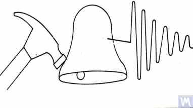
Figure 3.3. Diagram of Impact Excitation Used to Determine the Natural Frequencies of an Object
The mass of the hammer should approximately be 10% of the mass of the object being excited. To capture the vibrational response, a vibration sensor should be installed on the object under examination, with its measuring axis aligned with the direction of impact excitation. In some cases, a microphone from a noise measuring device may be used as a sensor to perceive the vibrational response of the object.
The vibrations of the object are converted into an electrical signal by the sensor, which is then sent to a measuring instrument, such as the input of a spectrum analyzer. This instrument records the time function and the spectrum of the decaying vibrational process (see Fig. 3.4), analysis of which allows determining the frequency (frequencies) of the object’s natural vibrations.
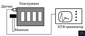
Figure 3.4. Diagram of Measurement and Recording of an Object’s Natural Vibrations
Like most modern vibration measuring instruments, the “Balanset” series measuring systems can be used to determine the natural frequencies of an object (e.g., supports of a balancing machine) when its vibrations are impact-excited. This procedure on “Balanset” series devices can be performed either in the additional functions mode of the device “Graphs. Spectrum” or in a specialized mode “Graphs. Impact”, which is included in the latest versions of the “Balanset 1” software.
As a result of this procedure, a working window with graphs of the time function and spectrum of decaying vibrations, which occur in the examined structure upon its impact excitation, is displayed on the computer screen. An example of such graphs is shown in Figure 3.5.

Figure 3.5. Program Interface Showing Time Function Graphs and Spectrum of Decaying Impact Vibrations of the Examined Structure
The analysis of the spectrum graph presented in Figure 3.5 (see the lower part of the work window) shows that the main component of the natural vibrations of the examined structure, determined with reference to the abscissa axis of the graph, occurs at a frequency of 9.5 Hz. This method can be recommended for studies of the natural vibrations of both Soft Bearing and Hard Bearing balancing machine supports.
3.1.3.2. Determining Natural Frequencies of Supports in Coasting Mode
In some cases, the natural frequencies of supports can be determined by cyclically measuring the amplitude and phase of vibration “on the coast.” In implementing this method, the rotor installed on the examined machine is initially accelerated to its maximum rotation speed, after which its drive is disconnected, and the frequency of the disturbing force associated with the rotor’s imbalance gradually decreases from maximum to the point of stop.
In this case, the natural frequencies of supports can be determined by two characteristics:
In the “Balanset” series devices, the “Vibrometer” mode (“Balanset 1”) or the “Balancing. Monitoring” mode (“Balanset 2C” and “Balanset 4”) can be used to detect the natural frequencies of objects “on the coast,” allowing cyclic measurements of amplitude and phase of vibration at the rotor’s rotational frequency.
Furthermore, the “Balanset 1” software additionally includes a specialized “Graphs. Coasting” mode, which allows plotting graphs of changes in amplitude and phase of support vibrations on the coast as a function of changing rotation frequency, significantly facilitating the process of diagnosing resonances.
It should be noted that, for obvious reasons (see section 3.1.1), the method of identifying natural frequencies of supports on the coast can only be used in the case of studying Soft Bearing balancing machines, where the working frequencies of rotor rotation significantly exceed the natural frequencies of supports in the transverse direction.
In the case of Hard Bearing machines, where the working frequencies of rotor rotation exciting the vibrations of supports on the coast are significantly below the natural frequencies of the supports, the use of this method is practically impossible.
3.1.4. Practical Recommendations for Designing and Manufacturing Supports for Balancing Machines 3.1.4.1. Soft Bearing Machines with Flat Plate Springs
Several design variations of balancing machine supports made with flat springs have been discussed above in section 2.1 and illustrated in Figures 2.7 – 2.9. According to our information, such designs are most commonly used in machines intended for balancing drive shafts.
As an example, let’s consider the spring parameters used by one of the clients (LLC “Rost-Service”, St. Petersburg) in the manufacturing of their own machine supports. This machine was intended for balancing 2, 3, and 4-support drive shafts, with a mass not exceeding 200 kg. The geometric dimensions of the springs (height * width * thickness) used in the supports of the leading and driven spindles of the machine, chosen by the client, were respectively 3002003 mm.
The natural frequency of the unloaded support, determined experimentally by the impact excitation method using the standard measuring system of the “Balanset 4” machine, was found to be 11 – 12 Hz. At such a natural frequency of vibrations of the supports, the recommended rotational frequency of the balanced rotor during balancing should not be lower than 22-24 Hz (1320 – 1440 RPM).
The geometric dimensions of the flat springs used by the same manufacturer on the intermediate supports were respectively 2002003 mm. Moreover, as the studies showed, the natural frequencies of these supports were higher, reaching 13-14 Hz.
Based on the test results, the manufacturers of the machine were advised to align (equalize) the natural frequencies of the spindle and intermediate supports. This should facilitate the selection of the range of operational rotational frequencies of the drive shafts during balancing and avoid potential instabilities of the measuring system’s readings due to the supports entering the area of resonant vibrations.
The methods for adjusting the natural frequencies of vibrations of supports on flat springs are obvious. This adjustment can be achieved by changing the geometric dimensions or shape of the flat springs, which is achieved, for example, by milling longitudinal or transverse slots that reduce their stiffness.
As previously mentioned, verification of the results of such adjustment can be conducted by identifying the natural frequencies of vibrations of the supports using the methods described in sections 3.1.3.1 and 3.1.3.2.
Figure 3.6 presents a classic version of the support design on flat springs, used in one of his machines by A. Sinitsyn. As shown in the figure, the support includes the following components:
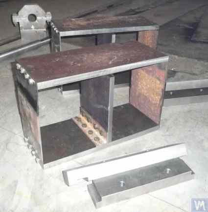
Figure 3.6. Design Variation of a Support on Flat Springs
The upper plate 1 of the support can be used to mount the spindle or an intermediate bearing. Depending on the purpose of the support, the lower plate 4 can be rigidly attached to the machine guides or installed on movable slides, allowing the support to move along the guides. Bracket 5 is used to install a locking mechanism for the support, enabling it to be securely fixed during the acceleration and deceleration of the balanced rotor.
Flat springs for Soft Bearing machine supports should be made from leaf-spring or high-quality alloyed steel. The use of ordinary structural steels with a low yield strength is not advisable, as they may develop residual deformation under static and dynamic loads during operation, leading to a reduction in the machine’s geometric accuracy and even to the loss of support stability.
3.1.4.2. Soft Bearing Machine Supports with Suspension on Strip Springs
In designing strip springs used for supporting suspensions, attention should be paid to selecting the thickness and width of the spring strip, which on one hand must withstand the static and dynamic load of the rotor on the support, and on the other hand, must prevent the possibility of torsional vibrations of the support suspension, manifesting as axial run-out.
Examples of structural implementation of balancing machines using strip spring suspensions are shown in Figures 2.1 – 2.5 (see section 2.1), as well as in Figures 3.7 and 3.8 of this section.
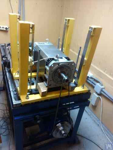
Figure 3.7. Machine for Balancing Electric Motor Rotors, Assembled, Developed by A. Mokhov.
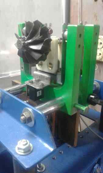
Figure 3.8. Machine for Balancing Turbopump Rotors, Developed by G. Glazov (Bishkek)
3.1.4.3. Soft Bearing Machine Supports Made Using Cylindrical Springs
An example of a Soft Bearing balancing machine, in which cylindrical compression springs are used in the design of the supports, is shown in Figure 3.9. The main drawback of this design solution is related to the varying degrees of spring deformation in the front and rear supports, which occurs if the loads on the supports are unequal during the balancing of asymmetrical rotors. This naturally leads to misalignment of the supports and skewing of the rotor axis in the vertical plane. One of the negative consequences of this defect may be the emergence of forces that cause the rotor to shift axially during rotation.
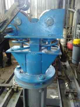
Fig. 3.9. Soft Bearing Support Construction Variant for Balancing Machines Using Cylindrical Springs.
3.1.4.4. Hard Bearing Supports for Machines As our extensive experience with clients shows, a significant portion of self-made balancer manufacturers have recently begun to prefer hard bearing machines with rigid supports. In section 2.2, Figures 2.16 – 2.18 depict photographs of various structural designs of machines employing such supports. A typical sketch of a rigid support, developed by one of our clients for their machine construction, is presented in Fig. 3.10. This support consists of a flat steel plate with a P-shaped groove, conventionally dividing the support into “rigid” and “flexible” parts. Under the influence of imbalance force, the “flexible” part of the support can deform relative to its “rigid” part. The magnitude of this deformation, determined by the thickness of the support, depth of the grooves, and width of the bridge connecting the “flexible” and “rigid” parts of the support, can be measured using appropriate sensors of the machine’s measuring system. Due to the lack of a method for calculating the transverse stiffness of such supports, taking into account the depth h of the P-shaped groove, width t of the bridge, as well as the thickness of the support r (see Fig. 3.10), these design parameters are typically determined experimentally by developers.
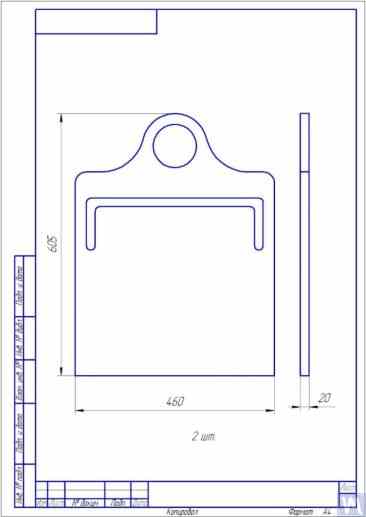
Fig. 3.10. Sketch of Hard Bearing Support for Balancing Machine
Photographs displaying various implementations of such supports, manufactured for our clients’ own machines, are presented in Figures 3.11 and 3.12. Summarizing the data obtained from several of our clients who are machine manufacturers, requirements for the thickness of supports, set for machines of various sizes and load capacities, can be formulated. For example, for machines intended to balance rotors weighing from 0.1 to 50-100 kg, the thickness of the support may be 20 mm.
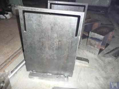
Fig. 3.11. Hard Bearing Supports for Balancing Machine, Manufactured by A. Sinitsyn
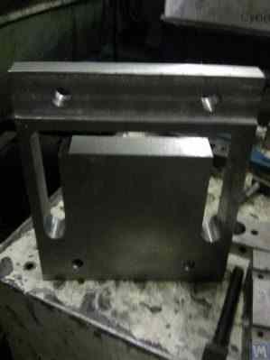
Fig. 3.12. Hard Bearing Support for Balancing Machine, Manufactured by D. Krasilnikov
For machines with a balanced rotor mass not exceeding 300 – 500 kg, the thickness of the support can be increased to 30 – 40 mm, and for machines designed for balancing rotors with maximum masses ranging from 1000 to 3000 kg, the thickness of the support can reach 50 – 60 mm or more. As the analysis of the dynamic characteristics of the above-mentioned supports shows, their natural vibration frequencies, measured in the transverse plane (the plane of measurement of relative deformations of the “flexible” and “rigid” parts), usually exceed 100 Hz or more. The natural vibration frequencies of Hard Bearing support stands in the frontal plane, measured in the direction coinciding with the axis of rotation of the balanced rotor, are usually significantly lower. And it is these frequencies that should be primarily considered when determining the upper limit of the operating frequency range for rotating rotors balanced on the machine. As noted above, the determination of these frequencies can be performed by the impact excitation method described in section 3.1.
3.2. Supporting Assemblies of Balancing Machines 3.2.1. Main Types of Supporting Assemblies In the manufacture of both Hard Bearing and Soft Bearing balancing machines, the following well-known types of supporting assemblies, used for the installation and rotation of balanced rotors on supports, can be recommended, including:

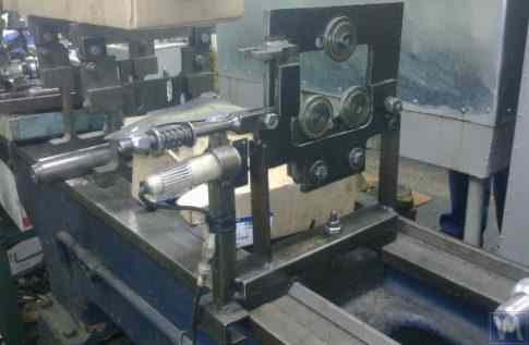
3.13. Execution Variant of Prismatic Supporting Assembly, Used on a Balancing Machine for Automobile Turbines
Similar supporting assemblies (see Figure 3.8 above) are implemented, for example, by G. Glazov in his machine, also intended for balancing automobile turbines. The original technical solution of the prismatic supporting assembly, made of fluoroplastic (see Figure 3.14), is proposed by LLC “Technobalance”.
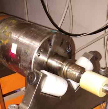
Fig. 3.14. Prismatic Support Assembly by LLC “Technobalance”
This particular supporting assembly is formed using two cylindrical sleeves 1 and 2, installed at an angle to each other and fixed on supporting axes. The balanced rotor contacts the surfaces of the sleeves along the generating lines of the cylinders, which minimizes the contact area between the rotor shaft and the support, consequently reducing the friction force in the support. If necessary, in case of wear or damage to the support surface in the area of its contact with the rotor shaft, the possibility of wear compensation is provided by rotating the sleeve around its axis by some angle. It should be noted that when using supporting assemblies made of non-metallic materials, it is necessary to provide for the structural possibility of grounding the balanced rotor to the machine body, which eliminates the risk of powerful static electricity charges occurring during operation. This, firstly, helps to reduce electrical interference and disturbances that may affect the performance of the machine’s measuring system, and secondly, eliminates the risk of personnel being affected by the action of static electricity.
3.2.1.2. Roller Supporting Assemblies These assemblies are typically installed on supports of machines designed for balancing rotors with masses exceeding 50 kilograms and more. Their use significantly reduces friction forces in the supports compared to prismatic supports, facilitating the rotation of the balanced rotor. As an example, Figure 3.15 shows a design variant of a supporting assembly where rollers are used for the positioning of the product. In this design, standard rolling bearings are used as rollers 1 and 2, the outer rings of which rotate on stationary axes fixed in the body of the machine’s support 3. Figure 3.16 depicts a sketch of a more complex design of a roller supporting assembly implemented in their project by one of the self-made manufacturers of balancing machines. As seen from the drawing, in order to increase the load capacity of the roller (and consequently the supporting assembly as a whole), a pair of rolling bearings 1 and 2 is installed in the roller body 3. The practical implementation of this design, despite all its obvious advantages, appears to be a rather complex task, associated with the need for independent fabrication of the roller body 3, to which very high requirements for geometric accuracy and mechanical characteristics of the material are imposed.
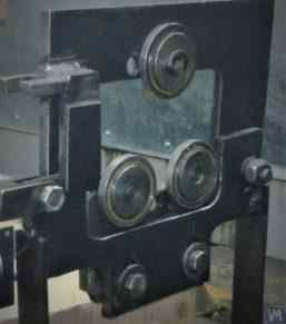
Fig. 3.15. Example of Roller Supporting Assembly Design
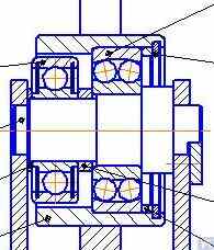
Fig. 3.16. Example of Roller Supporting Assembly Design with Two Rolling Bearings
Figure 3.17 presents a design variant of a self-aligning roller supporting assembly developed by the specialists of LLC “Technobalance”. In this design, the self-aligning capability of the rollers is achieved by providing them with two additional degrees of freedom, allowing the rollers to make small angular movements around the X and Y axes. Such supporting assemblies, ensuring high precision in the installation of balanced rotors, are usually recommended for use on supports of heavy balancing machines.
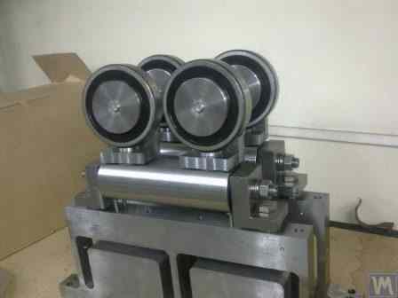
Fig. 3.17. Example of Self-Aligning Roller Supporting Assembly Design
As mentioned earlier, roller support assemblies typically have fairly high requirements for precision manufacturing and rigidity. In particular, the tolerances set for radial runout of the rollers should not exceed 3-5 microns.
In practice, this is not always achieved even by well-known manufacturers. For example, during the author’s testing of the radial runout of a set of new roller support assemblies, purchased as spare parts for the balancing machine model H8V, brand “K. Shenk”, the radial runout of their rollers reached 10-11 microns.
3.2.1.3. Spindle Supporting Assemblies
When balancing rotors with flange mounting (for example, cardan shafts) on balancing machines, spindles are used as supporting assemblies for positioning, mounting, and rotation of the balanced products.
Spindles are one of the most complex and critical components of balancing machines, largely responsible for achieving the required balancing quality.
The theory and practice of designing and manufacturing spindles are quite well developed and are reflected in a wide range of publications, among which, the monograph “Details and Mechanisms of Metal-Cutting Machine Tools” [1], edited by Dr. Eng. D.N. Reshetov, stands out as the most useful and accessible for developers.
Among the main requirements that should be considered in the design and manufacturing of balancing machine spindles, the following should be prioritized:
a) Providing high rigidity of the spindle assembly structure sufficient to prevent unacceptable deformations that may occur under the influence of unbalance forces of the balanced rotor;
b) Ensuring the stability of the spindle rotation axis position, characterized by permissible values of radial, axial, and axial runouts of the spindle;
c) Ensuring proper wear resistance of the spindle journals, as well as its seating and supporting surfaces used for mounting balanced products.
The practical implementation of these requirements is detailed in Section VI “Spindles and Their Supports” of work [1].
In particular, there are methodologies for verifying the rigidity and rotational accuracy of spindles, recommendations for selecting bearings, choosing spindle material and methods of its hardening, as well as much other useful information on this topic.
Work [1] notes that in the design of spindles for most types of metal-cutting machine tools, a two-bearing scheme is mainly used.
An example of the design variant of such a two-bearing scheme used in milling machine spindles (details can be found in work [1]) is shown in Fig. 3.18.
This scheme is quite suitable for the manufacture of balancing machine spindles, examples of design variants of which are shown below in Figures 3.19-3.22.
Figure 3.19 shows one of the design variants of the leading spindle assembly of a balancing machine, rotating on two radial-thrust bearings, each of which has its own independent housing 1 and 2. A flange 4, intended for flange mounting of a cardan shaft, and a pulley 5, used to transmit rotation to the spindle from the electric motor using a V-belt drive, are mounted on the spindle shaft 3.
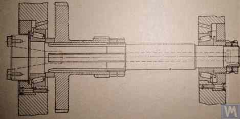
Fig. 3.18. Sketch of a Two-Bearing Milling Machine Spindle
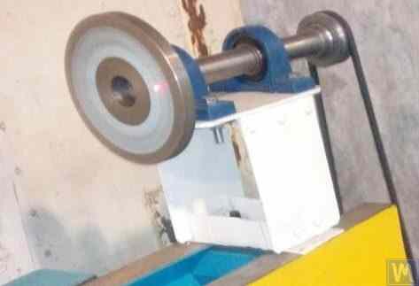
Figure 3.19. Example of Spindle Design on Two Independent Bearing Supports
Figures 3.20 and 3.21 show two closely related designs of leading spindle assemblies. In both cases, the spindle bearings are installed in a common housing 1, which has a through axial hole necessary for installing the spindle shaft. At the entrance and exit of this hole, the housing has special bores (not shown in the figures), designed to accommodate radial thrust bearings (roller or ball) and special flange covers 5, used to secure the outer rings of the bearings.
As in the previous version (see Fig. 3.19), a faceplate 2 is installed on the spindle shaft, intended for flange mounting of the drive shaft, and a pulley 3, used to transmit rotation to the spindle from the electric motor via a belt drive. A limb 4 is also fixed to the spindle shaft, which is used to determine the angular position of the spindle, utilized when installing test and corrective weights on the rotor during balancing.
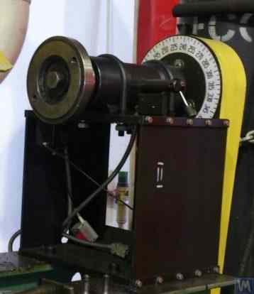
Figure 3.20. Example 1 of a Leading Spindle Design on Two Bearing Supports Installed in a Common Housing
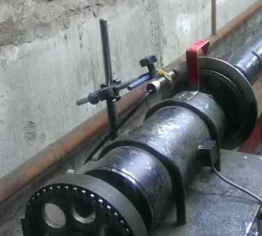
Figure 3.21. Example 2 of a Leading Spindle Design on Two Bearing Supports Installed in a Common Housing
 \
\
Figure 3.22. Example of a Design of a Driven (Rear) Spindle
Figure 3.22 shows a design variant of the driven (rear) spindle assembly of a machine, which differs from the leading spindle only by the absence of the drive pulley and limb, as they are not needed.
As seen in Figures 3.20 – 3.22, the spindle assemblies discussed above are attached to the Soft Bearing supports of balancing machines using special clamps (straps) 6. Other methods of attachment can also be used if necessary, ensuring proper rigidity and precision in positioning the spindle assembly on the support.
Figure 3.23 illustrates a design of flange mounting similar to that spindle, which can be used for its installation on a Hard Bearing support of a balancing machine.
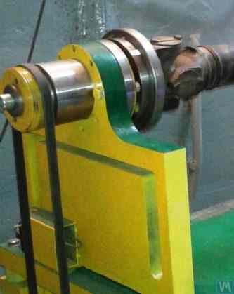
Figure 3.22. Example of Design Execution of a Driven (Rear) Spindle
Figure 3.22 presents a design variant of the driven (rear) spindle assembly of a machine, which only differs from the leading spindle in that it lacks the drive pulley and limb due to not being required.
As seen in Figures 3.20 – 3.22, the spindle assemblies discussed are attached to Soft Bearing supports of balancing machines using special clamps (straps) 6. When necessary, other methods of attachment that provide the proper rigidity and accuracy of positioning the spindle assembly on the support may also be used.
Figure 3.23 shows the design of a flange mounting for such a spindle, which can be used for its installation on a Hard Bearing support of a balancing machine.
3.1.4.3. Soft Bearing Machine Supports Made Using Cylindrical Springs
An example of a Soft Bearing balancing machine, in which cylindrical compression springs are used in the design of the supports, is shown in Figure 3.9. The main disadvantage of this design solution is related to the different amounts of spring deformation at the front and rear supports, which occurs in cases of unequal loads on the supports when balancing asymmetrical rotors. This naturally leads to misalignment of the supports and skewing of the rotor axis in the vertical plane. One of the negative consequences of this defect may be the occurrence of forces that cause the rotor to shift axially during rotation.
Figure 3.24. Calculation Scheme Used to Determine the Stiffness of the Spindle and Its Radial Runout (3.4)
Y=P∗ + 1جےB * (c+جی)2+جےB/جےاےc² ], انجیر (3.4)
where:
فارمولہ 3.4 کو تبدیل کرکے، سپنڈل اسمبلی کی سختی کی مطلوبہ حسابی قدر jшп تعین کیا جا سکتا ہے: jшп = P / Y، کلوگرام/سینٹی میٹر (3.5)
درمیانے درجے کی بیلنسنگ مشینوں کے لیے کام کی سفارشات [1] پر غور کرتے ہوئے، یہ قدر 50 کلوگرام/µm سے کم نہیں ہونی چاہیے۔
یہ پہلے ذکر کیا جا چکا ہے کہ سپنڈل اسمبلی کی ریڈیل سختی پر بنیادی اثر اس کے شافٹ کے قطر سے ہوتا ہے، جس میں اضافے کے ساتھ جڑتا J1 اور J2 کے لمحات چوکور طور پر بڑھ جاتے ہیں، اور اسی کے مطابق (مساوات 3.4 دیکھیں) رقم لچکدار نقل مکانی کے بوجھ کے نیچے تکلی کا Y کم ہوتا ہے۔
جیسا کہ مساوات 3.4 سے دیکھا گیا ہے، سپنڈل کی سختی سپورٹ کے درمیان فاصلے سے بھی متاثر ہوتی ہے۔ c اور اس کے کنسول کی لمبائی جی، جس کی اصلاح ڈیزائن کے دوران اسپنڈل اسمبلی کے معیار کو بھی نمایاں طور پر بڑھا دیتی ہے۔
واضح رہے کہ اسپنڈلز کو ڈیزائن کرتے وقت، ان کی محوری سختی کو یقینی بنانے پر بھی توجہ دی جانی چاہیے، جو بنیادی طور پر اسپنڈل بیرنگ کی محوری سختی اور اس کی رہائش کی سختی پر منحصر ہے۔
سپنڈل وائبریشنز کی موروثی فریکوئنسی، جو 500 - 600 ہرٹز سے کم نہیں ہونی چاہیے، اس کا براہ راست تعلق سپنڈل اسمبلیوں کی سختی سے ہے۔ اس پیرامیٹر کو تجرباتی طور پر "Balanset" سیریز کے آلات کے استعمال کے ذریعے طے کیا جا سکتا ہے جس پر پہلے سیکشن 3.1.3.1 میں زیر بحث اثر حوصلہ افزائی کے طریقہ کار کو استعمال کیا جا سکتا ہے۔
یہ دیکھتے ہوئے کہ اسپنڈل اسمبلیوں کے پیرامیٹرز کا تعین کرنا بہت سے ڈویلپرز کے لیے ایک اہم چیلنج پیش کرتا ہے، انہیں مشورہ دیا جاتا ہے کہ وہ کاموں میں پیش کردہ گرافیکل کیلکولیشن کے طریقہ کار کو استعمال کریں، جو کہ نوموگرامس کے استعمال پر مبنی ہے، جو اس کے حل کو نمایاں طور پر آسان بناتا ہے۔ کام اور اسے مکمل کرنے میں لگنے والے وقت کو کم کرتا ہے۔
3.2.1.3.4 سپنڈل گردش کے لیے درستگی کے تقاضوں کو یقینی بنانا
گھماؤ کی درستگی، اوپر بیان کردہ سختی کے ساتھ، بیلنسنگ مشین کی سپنڈل اسمبلی کی ایک اہم خصوصیت ہے، جو توازن کے معیار کو نمایاں طور پر متاثر کر سکتی ہے۔ پریکٹس سے پتہ چلتا ہے کہ سپنڈل کی گردش کی درستگی براہ راست کئی عوامل پر منحصر ہے، بشمول:
سب سے پہلے، مینوفیکچررز کو اپنے استعمال کردہ بیرنگ کی درستگی پر توجہ مرکوز کرنے کی ضرورت ہے، کیونکہ ان کا اثر دو بیئرنگ سپنڈل کی گردش کی درستگی (ریڈیل رن آؤٹ) پر ہوتا ہے (کیلکولیشن سکیم دیکھیں شکل 3.24فارمولہ 3.5 کا استعمال کرتے ہوئے ایک تصدیقی حساب سے اندازہ لگایا جا سکتا ہے۔
Δ = ∆B + جیc * (∆B + ∆اے) (3.5)
where:
3.2.1.3.5 سپنڈل بیلنس کی ضروریات کو یقینی بنانا
بیلنسنگ مشینوں کی سپنڈل اسمبلیاں اچھی طرح سے متوازن ہونی چاہئیں، کیونکہ کوئی بھی اصل عدم توازن اضافی خرابی کے طور پر متوازن ہونے کی وجہ سے روٹر میں منتقل ہو جائے گا۔ سپنڈل کے بقایا عدم توازن کے لیے تکنیکی رواداری کا تعین کرتے وقت، عام طور پر یہ مشورہ دیا جاتا ہے کہ اس کے توازن کی درستگی کی کلاس مشین پر متوازن ہونے والی پروڈکٹ سے کم از کم 1 - 2 کلاس زیادہ ہونی چاہیے۔
اوپر زیر بحث سپنڈلز کے ڈیزائن کی خصوصیات پر غور کرتے ہوئے، ان کا توازن دو طیاروں میں کیا جانا چاہیے۔
3.2.1.3.6 سپنڈل بیرنگ کے لیے بیئرنگ لوڈ کی صلاحیت اور پائیداری کی ضروریات کو یقینی بنانا
سپنڈلز کو ڈیزائن کرتے وقت اور بیئرنگ کے سائز کا انتخاب کرتے وقت، یہ مشورہ دیا جاتا ہے کہ ابتدائی طور پر بیرنگ کی پائیداری اور بوجھ کی صلاحیت کا جائزہ لیں۔ ان حسابات کو انجام دینے کے طریقہ کار کی تفصیل آئی ایس او 18855-94 (ISO 281-89) "رولنگ بیرنگ – ڈائنامک لوڈ ریٹنگز اور ریٹنگ لائف" [3] کے ساتھ ساتھ متعدد (بشمول ڈیجیٹل) رولنگ بیئرنگ ہینڈ بک میں دی جا سکتی ہے۔
3.2.1.3.7 سپنڈل بیرنگ کی قابل قبول حرارت کے لیے ضروریات کو یقینی بنانا
کام کی سفارشات کے مطابق [1]، سپنڈل بیرنگ کے بیرونی حلقوں کی زیادہ سے زیادہ قابل اجازت حرارت 70°C سے زیادہ نہیں ہونی چاہیے۔ تاہم، اعلیٰ معیار کے توازن کو یقینی بنانے کے لیے، بیرونی حلقوں کی تجویز کردہ حرارت 40 - 45 ° C سے زیادہ نہیں ہونی چاہیے۔
3.2.1.3.8 سپنڈل کے لیے بیلٹ ڈرائیو کی قسم اور ڈرائیو پللی کا ڈیزائن منتخب کرنا
بیلنسنگ مشین کے ڈرائیونگ سپنڈل کو ڈیزائن کرتے وقت، فلیٹ بیلٹ ڈرائیو کا استعمال کرتے ہوئے اس کی گردش کو یقینی بنانے کی سفارش کی جاتی ہے۔ سپنڈل آپریشن کے لیے اس طرح کی ڈرائیو کے صحیح استعمال کی ایک مثال پیش کی گئی ہے۔ اعداد و شمار 3.20 اور 3.23. وی بیلٹ یا ٹوتھڈ بیلٹ ڈرائیوز کا استعمال ناپسندیدہ ہے، کیونکہ یہ بیلٹ اور پللیوں میں ہندسی غلطیوں کی وجہ سے سپنڈل پر اضافی متحرک بوجھ لگا سکتے ہیں، جس کے نتیجے میں بیلنسنگ کے دوران پیمائش کی اضافی غلطیاں ہو سکتی ہیں۔ فلیٹ ڈرائیو بیلٹ کے لیے پلیوں کے لیے تجویز کردہ تقاضے ISO 17383- 73 "فلیٹ ڈرائیو بیلٹ کے لیے پلیاں" [4] میں بیان کیے گئے ہیں۔
ڈرائیو پللی کو اسپنڈل کے پچھلے سرے پر رکھا جانا چاہیے، جتنا ممکن ہو بیئرنگ اسمبلی کے قریب ہو (کم سے کم ممکنہ اوور ہینگ کے ساتھ)۔ گھرنی کی اوور ہینگنگ پلیسمنٹ کے لیے ڈیزائن کا فیصلہ، جس میں اسپنڈل کی تیاری میں بنایا گیا ہے۔ شکل 3.19، کو ناکام سمجھا جا سکتا ہے، کیونکہ یہ سپنڈل سپورٹ پر متحرک ڈرائیو لوڈ کے عمل کو نمایاں طور پر بڑھاتا ہے۔
اس ڈیزائن کی ایک اور اہم خرابی وی بیلٹ ڈرائیو کا استعمال ہے، مینوفیکچرنگ اور اسمبلی کی غلطیاں بھی اسپنڈل پر ناپسندیدہ اضافی بوجھ کا ذریعہ بن سکتی ہیں۔
3.3 بستر فریم)
بیڈ بیلنسنگ مشین کا بنیادی معاون ڈھانچہ ہے، جس پر اس کے اہم عناصر کی بنیاد ہے، بشمول سپورٹ پوسٹس اور ڈرائیو موٹر۔ بیلنسنگ مشین کے بیڈ کو منتخب کرتے یا تیار کرتے وقت، یہ یقینی بنانا ضروری ہے کہ یہ متعدد تقاضوں کو پورا کرتا ہے، بشمول ضروری سختی، جیومیٹرک درستگی، کمپن مزاحمت، اور اس کے گائیڈز کی پہننے کی مزاحمت۔
پریکٹس سے پتہ چلتا ہے کہ جب اپنی ضروریات کے لیے مشینیں تیار کرتے ہیں، تو بستر کے درج ذیل اختیارات سب سے زیادہ استعمال ہوتے ہیں:
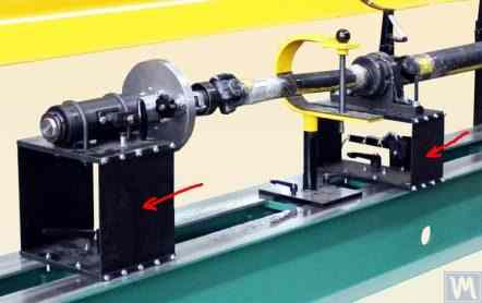
شکل 3.25 ایک لکڑی کے کام کرنے والی مشین کا بستر دکھاتا ہے جو کارڈن شافٹ کو متوازن کرنے کے لئے ڈیزائن کی گئی مشین کی تیاری میں کامیابی کے ساتھ استعمال کیا گیا تھا۔
شکل 3.25۔ کارڈن شافٹ کو بیلنس کرنے کے لیے مشین بنانے کے لیے استعمال شدہ ووڈ ورکنگ مشین بیڈ کے استعمال کی مثال۔
اعداد و شمار 3.26 اور 3.27 لیتھ بیڈز کے استعمال کی مثالیں دکھائیں، جن کی بنیاد پر اوجرز کو بیلنس کرنے کے لیے ایک خصوصی ہارڈ بیئرنگ مشین اور سلنڈرکل روٹرز کے لیے یونیورسل سافٹ بیئرنگ بیلنسنگ مشین تیار کی گئی تھی۔ DIY مینوفیکچررز کے لیے، اس طرح کے حل کم سے کم وقت اور لاگت کے ساتھ بیلنسنگ مشین کے لیے ایک سخت سپورٹ سسٹم بنانے کی اجازت دیتے ہیں، جس پر مختلف اقسام کے سپورٹ اسٹینڈز (ہارڈ بیئرنگ اور سافٹ بیئرنگ دونوں) لگائے جا سکتے ہیں۔ اس معاملے میں مینوفیکچرر کا بنیادی کام مشین گائیڈز کی ہندسی درستگی کو یقینی بنانا (اور اگر ضروری ہو تو بحال کرنا) ہے جس پر سپورٹ اسٹینڈز مبنی ہوں گے۔ DIY پیداواری حالات میں، عمدہ سکریپنگ کا استعمال عام طور پر گائیڈز کی مطلوبہ ہندسی درستگی کو بحال کرنے کے لیے کیا جاتا ہے۔

شکل 3.26۔ بیلنسنگ Augers کے لیے ہارڈ بیئرنگ مشین بنانے کے لیے استعمال شدہ لیتھ بیڈ کے استعمال کی مثال۔
شکل 3.27۔ بیلنسنگ شافٹ کے لیے نرم بیئرنگ مشین بنانے کے لیے استعمال شدہ لیتھ بیڈ کے استعمال کی مثال۔
شکل 3.28 دو چینلز سے بنائے گئے اسمبلڈ بیڈ کا ورژن دکھاتا ہے۔ اس بیڈ کی تیاری میں، ڈیٹیچ ایبل بولڈ کنکشن استعمال کیے جاتے ہیں، جس سے بیڈ کی اخترتی کو کم سے کم یا مکمل طور پر ختم کیا جا سکتا ہے بغیر کسی اضافی تکنیکی آپریشن کے اسمبلی کے دوران۔ مخصوص بیڈ کے گائیڈز کی درست جیومیٹرک درستگی کو یقینی بنانے کے لیے، استعمال کیے جانے والے چینلز کے اوپری فلینجز کی مکینیکل پروسیسنگ (پیسنے، باریک ملنگ) کی ضرورت پڑ سکتی ہے۔

شکل 3.28۔ چینلز سے اسمبلڈ بیڈ بنانے کی مثال
اعداد و شمار 3.29 اور 3.30 ویلڈڈ بیڈز کی موجودہ مختلف حالتیں بھی دو چینلز سے بنی ہیں۔ اس طرح کے بستروں کے لیے مینوفیکچرنگ ٹیکنالوجی کے لیے اضافی آپریشنز کی ایک سیریز کی ضرورت پڑ سکتی ہے، جیسے کہ ویلڈنگ کے دوران ہونے والے اندرونی دباؤ کو دور کرنے کے لیے گرمی کا علاج۔ اسمبلڈ بیڈز کی طرح، ویلڈڈ بیڈز کے گائیڈز کی درست جیومیٹرک درستگی کو یقینی بنانے کے لیے، استعمال کیے جانے والے چینلز کے اوپری فلینجز کی مکینیکل پروسیسنگ (پیسنے، باریک ملنگ) کی منصوبہ بندی کی جانی چاہیے۔

شکل 3.29۔ چینلز سے ویلڈڈ بیڈ بنانے کی مثال
تصویر 3.30۔ چینلز سے ویلڈڈ بیڈ تیار کرنے کی مثال
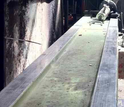
حال ہی میں، کمپن ڈیمپنگ کوٹنگز کے ساتھ پولیمر کنکریٹ سے بنے بستر بڑے پیمانے پر استعمال ہونے لگے ہیں۔ بستروں کی تیاری کے لیے اس ٹیکنالوجی کو آن لائن اچھی طرح سے بیان کیا گیا ہے اور اسے DIY مینوفیکچررز آسانی سے لاگو کر سکتے ہیں۔ نسبتاً سادگی اور پیداوار کی کم لاگت کی وجہ سے، ان بستروں کے اپنے دھاتی ہم منصبوں پر کئی اہم فوائد ہیں:
عام طور پر، ایسے بستروں کو تیار کرتے وقت، ان کے اوپری حصے کو گائیڈ کے طور پر استعمال ہونے والے اسٹیل انسرٹس سے مضبوط کیا جاتا ہے جس پر بیلنسنگ مشین کے سپورٹ اسٹینڈ ہوتے ہیں۔ مثال کے طور پر، شکل 3.31 کارڈن شافٹ کو بیلنس کرنے والی مشین کی تصویر دکھاتی ہے، جسے LLC "Technobalance" نے تیار کیا ہے، جس کا بستر پولیمر کنکریٹ سے بنا ہے۔

شکل 3.31۔ پولیمر کنکریٹ سے بنے بیلنسنگ مشین بیڈ کی مثال
3.4 بیلنسنگ مشینوں کے لیے ڈرائیوز
جیسا کہ ہمارے کلائنٹس کی طرف سے بیلنسنگ مشینوں کی تیاری میں استعمال کیے جانے والے ڈیزائن سلوشنز کا تجزیہ ظاہر کرتا ہے، وہ بنیادی طور پر ڈرائیوز کے ڈیزائن کے دوران متغیر فریکوئنسی ڈرائیوز سے لیس AC موٹرز کے استعمال پر توجہ مرکوز کرتے ہیں۔ یہ نقطہ نظر کم سے کم لاگت کے ساتھ متوازن روٹرز کے لئے ایڈجسٹ گردش کی رفتار کی ایک وسیع رینج کی اجازت دیتا ہے۔ متوازن روٹرز کو گھمانے کے لیے استعمال ہونے والی مین ڈرائیو موٹرز کی طاقت کا انتخاب عام طور پر ان روٹرز کے بڑے پیمانے پر کیا جاتا ہے اور تقریباً یہ ہو سکتا ہے:
ان موٹروں کو مشین کے بستر یا اس کی بنیاد پر سختی سے نصب کیا جانا چاہئے۔ مشین پر انسٹال کرنے سے پہلے (یا انسٹالیشن سائٹ پر)، مین ڈرائیو موٹر، اس کے آؤٹ پٹ شافٹ پر لگائی گئی گھرنی کے ساتھ، احتیاط سے متوازن ہونا چاہیے۔ متغیر فریکوئنسی ڈرائیو کی وجہ سے برقی مقناطیسی مداخلت کو کم کرنے کے لیے، اس کے ان پٹ اور آؤٹ پٹ پر نیٹ ورک فلٹرز کو انسٹال کرنے کی سفارش کی جاتی ہے۔ یہ معیاری آف دی شیلف پروڈکٹس ہو سکتے ہیں جو ڈرائیوز کے مینوفیکچررز کے ذریعے فراہم کیے جاتے ہیں یا فیرائٹ رِنگز کا استعمال کرتے ہوئے بنائے گئے گھریلو فلٹرز۔
