Understanding Residual Unbalance







Residual unbalance is the amount of unbalance that remains in a rotor after the balancing process is complete. It is the small, deliberate amount of unbalance that is allowed to stay within the rotor because reducing it further would bring no practical benefit. In other words, residual unbalance is not a failure of balancing — it is the target of balancing.
1. Definition: What is Residual Unbalance?
Every real rotor carries some unbalance. Perfect balance — a mass axis that coincides exactly with the shaft axis — cannot be achieved, and chasing it is economically pointless. The job of balancing is therefore not to eliminate unbalance but to push it below a level where the vibration it produces is harmless to the machine. The unbalance that is left over once that level is reached is the residual unbalance.
Residual unbalance is expressed as a mass multiplied by a radius — typically in gram-millimetres (g·mm) or gram-inches — because the centrifugal force a rotor feels depends on both how much mass is off-centre and how far from the axis it sits. A 1 g heavy spot at a 100 mm radius (100 g·mm) is equivalent, in its effect, to a 2 g heavy spot at 50 mm.
2. Balancing Tolerance — How Much is Allowed?
The maximum permissible residual unbalance is set by a balancing tolerance. The internationally accepted method comes from ISO 1940-1, now folded into the modern ISO 21940-11 series. It defines Balance Quality Grades (G-grades) — G6.3, G2.5, G1.0 and so on — where the number is the permissible orbital velocity of the rotor’s centre of mass in mm/s.
- A lower G number means a tighter tolerance and a smaller permissible residual unbalance. Pump and fan rotors are usually G6.3; precision machine-tool spindles demand G1.0 or better.
- The permissible residual unbalance grows with rotor mass and falls as service speed rises — a fast rotor must be balanced far more precisely than a slow one of the same mass.
The arithmetic — turning a G-grade and a service speed into an allowable g·mm value, then splitting it between the two correction planes — is easy to get wrong by hand. You can work it out instantly with our free Residual Unbalance Calculator (ISO 21940-11), which converts a G-grade and service speed straight into the permissible g·mm for each plane.
3. Why Residual Unbalance Always Exists
Several practical realities guarantee that some unbalance always survives:
- Instrument resolution: every balancing machine and field analyser has a smallest unbalance it can reliably resolve.
- Tooling and mounting errors: arbors, mandrels and adapters introduce tiny eccentricities of their own.
- Assembly shift: keys, couplings and fasteners move a rotor’s mass slightly when the machine is reassembled after balancing.
- Operational change: thermal growth, wear, erosion and product build-up all alter a rotor’s balance state in service.
- Diminishing returns: halving the residual unbalance can double the balancing time, so there is a sensible point to stop.
4. Measuring and Verifying Residual Unbalance
Balancing is an iterative loop: measure the current unbalance, add or remove a correction weight, re-measure, and repeat until the reading drops below the tolerance. A complete balancing report should always state both the initial unbalance and the final residual unbalance for each plane — for example, “0.5 g·mm left plane, 0.8 g·mm right plane, within G2.5 at 3000 rpm.”
On assembled machines this verification happens on-site rather than on a balancing machine. A portable two-channel analyser such as the Balanset-1A measures the 1× amplitude and phase before and after correction, computes the influence coefficients of the rotor, and confirms that the residual vibration — and therefore the residual unbalance — sits inside the chosen ISO 21940-11 grade. Because it works in the machine’s own bearings at operating speed, it captures the true residual state the rotor will actually run in, including assembly and thermal effects that a balancing machine cannot see.
5. Residual Unbalance vs Initial Unbalance
It helps to keep two terms distinct. Initial unbalance is what the rotor has before any correction — often large and the reason vibration was noticed in the first place. Residual unbalance is what is intentionally left after correction, verified against tolerance. The ratio between them is a useful measure of how effective the balancing job was: reducing a rotor from 250 g·mm to 4 g·mm represents a better than 98% reduction and a clean pass for most industrial grades.
From G Grade to a Number on the Screen
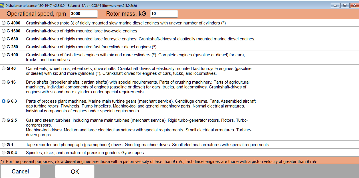
In the Balanset software the tolerance above is not typed in from a memorised table. The “ISO 1940…” button beside the tolerance field opens a dialog listing the G grades together with their typical rotor families; pick a grade, enter the service speed and the rotor mass, and “OK” transfers the computed permissible residual unbalance straight into the tolerance field.
The computation is the standard Uper = 1000 · G · M / (2π · f) in g·mm, with G in mm/s, M in kg and f the rotation frequency in Hz — G 6.3 at 3000 rpm on a 10 kg rotor gives ≈ 200 g·mm. For a two-plane job the tolerance is split evenly, half per correction plane; with imperial units selected the value is shown and checked in oz·in.
After correction the program compares the achieved residual unbalance against this tolerance and colours the result green (within) or red (exceeded); the tolerance is stored with the archive record and repeated in the HTML report, so the pass/fail verdict survives beyond the day of the job.