Understanding Static Balancing (Single-Plane Balancing)


Definition: What is Static Balancing?
Static balancing is the simplest form of rotor balancing. It is a process that corrects for static unbalance, a condition where a rotor’s center of mass is offset from its axis of rotation, creating a single “heavy spot.” This type of balancing can, in theory, be performed with the rotor at rest (statically). If a rotor with pure static unbalance were placed on a frictionless surface (like knife edges), it would rotate until the heavy spot settled at the lowest point due to gravity.
Static balancing involves making a correction in a single plane to counteract this heavy spot. The correction is a single weight placed 180° opposite the heavy spot to bring the center of mass back to the center of rotation.
Static Unbalance vs. Dynamic Unbalance
Static unbalance is also known as “force unbalance” because it creates a centrifugal force that acts radially outwards from the center of rotation. However, it does not create any “couple” or rocking motion. This is in contrast to dynamic unbalance, which is a combination of both force and couple unbalance and requires corrections in at least two planes to be fully resolved. A rotor can be perfectly statically balanced but still have a significant couple unbalance that will cause it to vibrate severely when it rotates.
When is Static Balancing Sufficient?
Static balancing is only an appropriate and sufficient method for a specific class of rotors. It is generally reserved for components that are very narrow or disc-shaped, where the axial length is very small compared to the diameter. For these types of rotors, it is unlikely that a significant couple unbalance could exist.
Common examples of rotors where single-plane static balancing is often sufficient include:
- Grinding wheels
- Automotive wheels and tires
- Single, narrow fan or blower wheels
- Flywheels
- Pulleys and sheaves
For any rotor that has a significant length (e.g., a motor armature, a multi-stage pump, or a long shaft), static balancing alone is inadequate, and dynamic balancing is required.
Methods of Static Balancing
1. Knife-Edge Balancing
This is the classic, non-rotating method. The rotor is placed on a pair of parallel, level, and low-friction knife edges. The rotor will roll until its heaviest point is at the bottom. A temporary weight is then added to the top (180° opposite) until the rotor will stay in any position it is placed without rolling. This weight is then made permanent.
2. Vertical Balancing Machine
Modern static balancing is often performed on a vertical balancing machine. The rotor (like a flywheel or a tire) is placed on a horizontal plate that is supported by force sensors. The machine spins the rotor at a low speed, and the sensors measure the direction and magnitude of the unbalance force, displaying the required correction on a screen.
3. Single-Plane Field Balancing (Balanset-1A)
Static (single-plane) balancing can also be performed on an assembled machine using a portable balancing system. With Balanset-1A, the “Balancing in one plane (“static”)” mode measures rotor speed (RPM) and the vector of the 1x vibration (RMS value and phase). Based on the “Run #0” and “Run #1” measurements, the software automatically calculates the mass and installation angle of the corrective weight needed to reduce the rotor’s imbalance.
Balancing results are saved to an archive, and after completion a balancing report can be generated, edited, and printed in the built-in report editor.
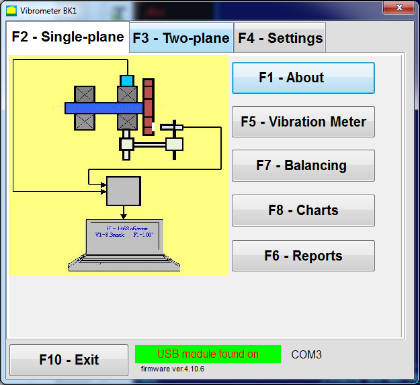
How single-plane balancing is performed in the Balanset-1A program
- Install sensors and connect the system. Install the vibration sensor at the selected measurement point and connect it to the device. Install the phase sensor (tachometer), apply reflective tape on the rotor, and connect the device to a Windows laptop.
- Start Single-Plane Balancing mode. In the main operating window select “Single-plane” mode and start balancing mode. The program will open the single-plane balancing archive window.
- Create an archive record. Enter the rotor name, place of installation, tolerances (vibration and residual imbalance), and the date. The software will create an archive folder where charts and report files will be saved.
- Set balancing parameters in “Balancing settings”.
- Influence coefficient: choose “New Rotor” (two runs to calibrate) or “Saved coeff.” (one run, for the same type of machine with saved influence coefficients).
- Trial weight mass: choose “Gramm” or “Percent”. If you plan to use “Saved coeff.” mode later, enter the trial weight mass in grams (weigh it on the scales).
- Weight Attachment Method: choose “Circum” (any angle on circumference) or “Fixed position” (fixed holes/blades/positions; enter the number of positions).
- Mass mount radius: enter the radius used for mounting the trial and correction weights.
- Leave trial weight in Plane1: enable this only if you cannot remove the trial weight during the process.
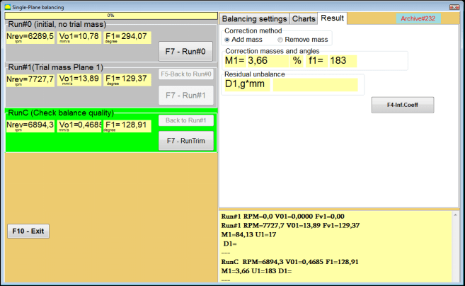
- Run #0 (initial run, no trial weight). Bring the machine to stable speed and start “Run #0” to measure the initial vibration. The software records RPM, RMS value and phase of the 1x vibration component. The “Charts” tab shows the waveform and spectrum.
- Install the trial weight. Stop the machine and install the trial weight at a known radius. The trial weight must change vibration amplitude or phase significantly. A common criterion is the “30/30 rule”: the trial weight should change the amplitude by about 30% (lower or higher) or the phase by about 30° or more. If you plan to use “Saved coeff.” mode later, install the trial weight at the same angle as the reflective mark.
- Run #1 (trial weight installed). Restart the machine, wait for stable speed, and perform “Run #1”. The software calculates the corrective weight parameters.
- Install the correction weight. Stop the machine, remove the trial weight, and install the correction weight. The installation angle is counted from the trial weight position in the direction of rotor rotation. Install the correction weight on the same radius as the trial weight.
- RunTrim (check balance quality). Perform “RunTrim” to verify the balancing result. If residual vibration and/or residual unbalance meet the tolerance, the balancing can be completed. If not, the software will calculate an additional corrective weight and balancing can continue by successive approximations.
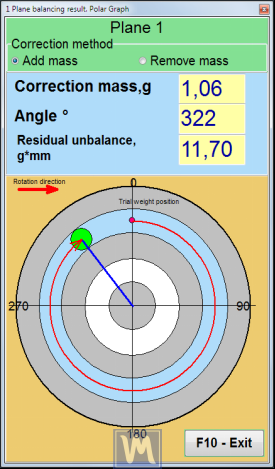
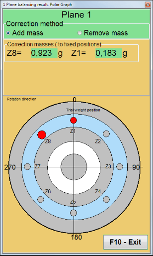
Result visualization: polar graph and fixed positions
Balanset-1A can display correction weight mass and angle in a polar coordinate view. If “Fixed position” is selected, the program can automatically split the corrective weight into two parts and show the position numbers where each part must be installed.
Limitations
The primary limitation of static balancing is its inability to detect or correct couple unbalance. Applying a static balance to a rotor that actually has a dynamic unbalance can sometimes make the vibration worse by correcting the force component but ignoring or exacerbating the couple component. For this reason, for most industrial machinery, two-plane dynamic balancing is the standard and required practice.
