
PORTABLE BALANCER "BALANSET-1A"
ДК-ге негізделген екі арналы динамикалық теңгерім жүйесі
OPERATION MANUAL
rev. 1.56 May 2023
2023 | Estonia, Narva
SAFETY NOTICE: Бұл құрылғы ЕО қауіпсіздік стандарттарына сәйкес келеді. 2-сыныпты лазерлік өнім. Айналмалы жабдықпен жұмыс істеу қауіпсіздік тәртібін сақтаңыз. Толық қауіпсіздік ақпаратын төменде қараңыз →
1. ТЕҢГЕРУ ЖҮЙЕСІНЕ ШОЛУ
Balanset-1A balancer желдеткіштер, тас кескіш дөңгелектер, шпиндельдер, ұсатқыштар, сорғылар және басқа да айналмалы механизмдер үшін бір жазықтықтағы және екі жазықтықтағы динамикалық теңгерімдеу қызметтерін ұсынады.
Balanset-1A теңгерімдеуші екі вибросенсорды (акселерометр), лазерлік фаза сенсорын (тахометр), алдын ала күшейткіштері, интеграторлары және АЦТ модулі бар 2 арналы USB интерфейс блогын, сондай-ақ Windows негізіндегі теңгерімдеу бағдарламалық жасақтамасын қамтиды. Balanset-1A ноутбукты немесе Windows (WinXP...Win11, 32 не 64 бит) үйлесімді басқа ДК талап етеді.
Balancing software provides the correct balancing solution for single-plane and two-plane balancing automatically. Балансет-1А is simple to use for non-vibration experts.
All balancing results saved in archive and can be used to create the reports.
Key Features
Easy to Use
- • Пайдаланушы таңдайтын сынақ массасы
- • Сынақ массасының жарамдылығы туралы қалқымалы хабар
- • Деректерді қолмен енгізу
Өлшеу мүмкіндіктері
- • айн/мин, амплитуда және фаза
- • ЖФТ спектрін талдау
- • Толқын пішінін және спектрді көрсету
- • Екі арналы бір мезгілдегі деректер
Кеңейтілген функциялар
- • Сақталған ықпал коэффициенттері
- • Дәл реттеу теңгерімдеуі
- • Дорн эксцентриситетін есептеу
- • ISO 1940 төзімділігін есептеу
Деректерді басқару
- • Теңгерімдеу деректерін шектеусіз сақтау
- • Тербеліс толқын пішінін сақтау
- • Мұрағат және есептер
Есептеу құралдары
- • Бөлінген салмақты есептеу
- • Бұрғылау есебі
- • Түзету жазықтықтарын өзгерту
- • Полярлық графикті визуализациялау
Талдау параметрлері
- • Сынақ салмақтарын алу немесе қалдыру
- • RunDown диаграммалары (тәжірибелік)
2. SPECIFICATION
| Parameter | Specification |
|---|---|
| Measurement range of the root-mean-square value (RMS) of the vibration velocity, mm/sec (for 1x vibration) | from 0.2 to 80 |
| The frequency range of the RMS measurement of the vibration velocity, Hz | from 5 to 1000 (amplitude error ≤10% above 550 Hz) |
| Number of the correction planes | 1 or 2 |
| Range of the frequency of rotation measurement, rpm | 250 – 90000 |
| Range of the vibration phase measurement, angular degrees | from 0 to 360 |
| Error of the vibration phase measurement, angular degrees | ± 1 |
| Тербеліс жылдамдығының СКМ мәнін өлшеу дәлдігі | ±(0.1 + 0.1×Vmeasured) mm/sec |
| Айналу жиілігін өлшеу дәлдігі | ±(1 + 0.005×Nmeasured) rpm |
| Орташа істен шығуға дейінгі уақыт (MTBF), сағат, мин | 1000 |
| Орташа қызмет ету мерзімі, жыл, мин | 6 |
| Өлшемдер (қатты қорапта), см | 39*33*13 |
| Mass, kg | <5 |
| Тербеліс датчигінің жалпы өлшемдері, мм, макс | 25*25*20 |
| Тербеліс датчигінің массасы, кг, макс | 0.04 |
|
Жұмыс жағдайлары: - Temperature range: from 5°C to 50°C - Салыстырмалы ылғалдылық: < 85%, қанықпаған - Күшті электр-магниттік өріссіз & күшті соққысыз |
|
3. PACKAGE
Balanset-1A теңгергіші екі бір осьті акселерометрді, лазерлік фазалық бастапқы нүкте маркерін (цифрлық тахометрді), алдын ала күшейткіштері, интеграторлары және АЦТ деректерді алу модулі бар 2-арналы USB интерфейс блогын және Windows негізіндегі баланстау бағдарламалық жасақтамасын қамтиды.
Delivery Set
| Сипаттама | Number | Note |
|---|---|---|
| USB interface unit | 1 | |
| Laser phase reference marker (tachometer) | 1 | |
| Бір осьті акселерометрлер | 2 | |
| Magnetic stand | 1 | |
| Digital scales | 1 | |
| Hard case for transportation | 1 | |
| "Balanset-1A". Пайдаланушы нұсқаулығы. | 1 | |
| Flash disk with balancing software | 1 |
4. BALANCE PRINCIPLES
4.1. "Balanset-1A" құрамына кіреді (4.1-сурет): USB интерфейс блогы (1), екі акселерометр (2) and (3), фазалық реперлік маркер (4) және портативті дербес компьютер (жеткізу жиынтығына кірмейді) (5).
Жеткізу жиынтығына магниттік тіреу де кіреді (6) ) used for mounting the phase reference marker and digital scales 7.
X1 and X2 connectors intended for connection of the vibration sensors respectively to 1 and 2 measuring channels, and the X3 connector used for connection of the phase reference marker.
The USB cable provides power supply and connection of the USB interface unit to the computer.

Сур. 4.1. "Balanset-1A" жеткізу жиынтығы
Mechanical vibrations cause an electrical signal proportional to the vibration acceleration on the output of the vibration sensor. Digitized signals from ADC module transferred via USB to the portable PC ( (5). Фазалық реперлік маркер айналу жиілігі мен тербеліс фазалық бұрышын есептеу үшін пайдаланылатын импульстік сигнал генерациялайды. Windows негізіндегі бағдарламалық қамтамасыз ету бір жазықтықта және екі жазықтықта теңгерімдеу, спектрлік талдау, графиктер, есептер, ықпал коэффициенттерін сақтау мүмкіндіктерін қамтамасыз етеді
5. SAFETY PRECAUTIONS
⚡ НАЗАР АУДАРЫҢЫЗ — Электр қауіпсіздігі
5.1. When operating on 220V electrical safety regulations must be observed. It is not allowed to repair the device when connected to 220 V.
5.2. Егер сіз құрылғыны сапасы төмен айнымалы ток желісінде немесе желілік кедергілер болған жағдайда пайдалансаңыз, компьютердің аккумулятор батареясынан автономды қоректендіруді пайдалану ұсынылады.
⚠️ Айналмалы жабдықтарға арналған қосымша қауіпсіздік талаптары
- !Машинаны блоктау: Датчиктерді орнатпас бұрын сенімді блоктау/белгілеу рәсімдерін міндетті түрде орындаңыз
- !Жеке қорғаныс құралдары: Қауіпсіздік көзілдірігін киіңіз, есту органдарын қорғаңыз және айналмалы механизмдерге жақын жерде еркін іліп тұрған киімнен аулақ болыңыз
- !Сенімді бекіту: Барлық датчиктер мен кабельдердің берік бекітілгенін және айналмалы бөліктерге ілінбейтінін қамтамасыз етіңіз
- !Төтенше жағдай рәсімдері: Авариялық тоқтату түймелерінің орналасқан жерін және жабдықты өшіру рәсімдерін біліңіз
- !Training: Айналмалы машиналарда тепе-теңдеу жабдығын тек арнайы дайындалған қызметкерлер ғана пайдалануы тиіс
6. БАҒДАРЛАМАЛЫҚ ЖӘНЕ АППАРАТТЫҚ ПАРАМЕТРЛЕР
6.1. USB drivers and balancing software installation
Before working install drivers and balancing software.
Қалталар мен файлдар тізімі
Installation disk (flash drive) contains the following files and folders:
- Bs1Av###Setup – «Balanset-1A» теңдеу бағдарламалық жасақтамасы бар қалта (### – нұсқа нөмірі)
- ArdDrv – USB drivers
- EBalancer_manual.pdf – this manual
- Bal1Av###Setup.exe – орнату файлы. Бұл файлда жоғарыда аталған барлық мұрағатталған файлдар мен қалталар бар. ### – «Balanset-1A» бағдарламалық жасақтамасының нұсқасы.
- Ebalanc.cfg – сезімталдық мәні
- Bal.ini – кейбір инициализациялау деректері
Бағдарламалық жасақтаманы орнату рәсімі
For installing drivers and specialized software run file Bal1Av###Setup.exe and follow setup instructions by pressing buttons «Next», «ОК» etc.
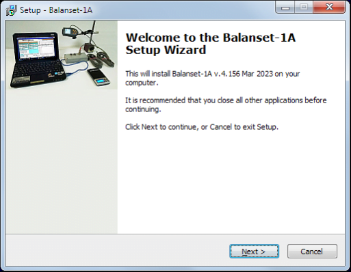
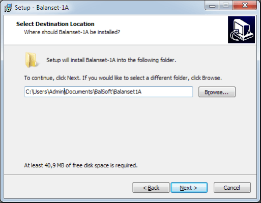
Choose setup folder. Usually the given folder should not be changed.
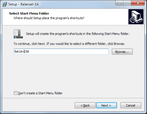
Then the program requires specifying Program group and desktop folders. Press button Next.
Орнатуды аяқтау
- ✓Install sensors on the inspected or balanced mechanism (Detailed information about how to install the sensors is given in Annex 1)
- ✓Connect vibration sensors 2 and 3 to the inputs X1 and X2, and phase angle sensor to the input X3 of USB interface unit.
- ✓Connect USB interface unit to the USB-port of the computer.
- ✓Айнымалы ток қоректендіргішін пайдаланған кезде компьютерді желіге қосыңыз. Қоректендіргішті 220 В, 50 Гц желісіне қосыңыз.
- ✓Жұмыс үстеліндегі «Balanset-1A» таңбашасын басыңыз.
7. ТЕҢГЕРУ БАҒДАРЛАМАЛЫҚ ҚАМТАМАСЫЗ ЕТУІ
7.1. General
Initial window
«Balanset-1A» бағдарламасы іске қосылғанда 7.1-суретте көрсетілген бастапқы терезе пайда болады.

Сурет 7.1. «Balanset-1A» бастапқы терезесі
Бастапқы терезеде басқан кезде іске асырылатын функциялардың атауы бар 9 түйме орналасқан.
F1-«About»
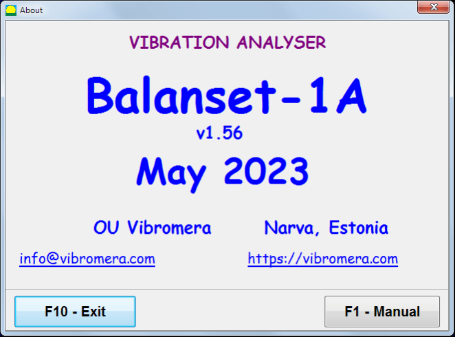
Сурет 7.2. F1-«Туралы» терезесі
F2-«Single plane», F3-«Two plane»
Pressing "F2- Single-plane" (or F2 function key on the computer keyboard) selects the measurement vibration on the X1.
After clicking this button, the computer display diagram shown in Fig. 7.1 illustrating a process of measuring the vibration only on the first measuring channel (or the balancing process in a single plane).
Pressing the "F3-Two-plane" (or F3 function key on the computer keyboard) selects the mode of vibration measurements on two channels X1 and X2 simultaneously. (Fig. 7.3.)
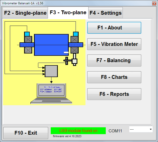
Сурет 7.3. «Balanset-1A» бастапқы терезесі. Екі жазықтықта теңдеу.
F4 – «Параметрлер»
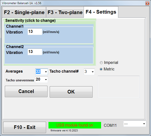
Сурет 7.4. «Параметрлер» терезесі
In this window you can change some Balanset-1A settings.
- Sensitivity. The nominal value is 13 mV / mm/s.
Changing the sensitivity coefficients of sensors is required only when replacing sensors!
Attention!
Сезімталдық коэффициентін енгізген кезде оның бөлшек бөлігі бүтін бөліктен ондық нүктемен (« , » белгісімен) бөлінеді.
- Averaging – number of averaging (number of revolutions of the rotor over which data is averaged to more accuracy)
- Tacho channel# – тахометр қосылған арна нөмірі. Әдепкі бойынша – 3-ші арна.
- Unevenness – іргелес тахометр импульстері арасындағы уақыт айырмашылығы, оның асып кетуі «Failure of the tachometer"
- Imperial/Metric - Өлшем бірліктері жүйесін таңдаңыз.
Com port number is assigned automatically.
F5 – «Вибрация өлшеуіші»
Pressing this button (or a function key of F5 on the computer keyboard) activates the mode of vibration measurement on one or two measuring channels of virtual Vibration meter depending on the buttons condition “F2-бір жазықтықтағы", "F3-two-plane".
F6 – «Reports»
Pressing this button (or F6 function key on the computer keyboard) switches on the balancing Archive, from which you can print the report with the results of balancing for a specific mechanism (rotor).
F7 – «Balancing»
Pressing this button (or function key F7 on your keyboard) activates balancing mode in one or two correction planes depending on which measurement mode is selected by pressing the buttons “F2-бір жазықтықтағы", "F3-two-plane".
F8 – «Charts»
Pressing this button (or F8 function key on the computer’s keyboard) enables graphic Vibration meter, the implementation of which displays on a display simultaneously with the digital values of the amplitude and phase of the vibration graphics of its time function.
F10 – «Exit»
Pressing this button (or F10 компьютер пернетақтасындағы функционалды перне) «Balanset-1A» бағдарламасын аяқтайды.
7.2. "Вибрация өлшеуіші"
"Vibration meter" режимінде жұмыс бастамас бұрын, вибрация сенсорларын машинаға орнатып, оларды USB интерфейс блогының X1 және X2 қосқыштарына тиісінше жалғаңыз. Тахо сенсорын USB интерфейс блогының X3 кірісіне жалғау қажет.

Fig. 7.5 USB interface unit
Тахо сенсорының жұмысы үшін ротор бетіне шағылыстырғыш таспа жабыстырыңыз.

Сур. 7.6. Шағылыстырғыш таспа.
Recommendations for the installation and configuration of sensors are given in Annex 1.
Вибрация өлшеуіші режимінде өлшеуді бастау үшін бағдарламаның бастапқы терезесіндегі "F5 – Vibration Meter" түймесін басыңыз (сур. 7.1-ді қараңыз).
Vibration Meter window appears (see. Fig.7.7)

Fig. 7.7. Vibration meter mode. Wave and Spectrum.
Вибрация өлшеуін бастау үшін "F9 – Run" (немесе функционалды перне F9 on the keyboard).
If Триггер режимі: Авто is checked – the results of vibration measurements will be periodically displayed on the screen.
In case of simultaneous measurement of vibration on the first and second channels, the windows located beneath the words “Plane 1" and "Plane 2" толтырылады.
Vibration measuring in the “Vibration” mode also may be carried out with disconnected phase angle sensor. In the Initial window of the program the value of the total RMS vibration (V1s, V2s) will only be displayed.
Вибрация өлшеуіші режимінде келесі параметрлер қолжетімді
- RMS Low, Hz – жалпы вибрацияның СКМ мәнін есептеу үшін ең төменгі жиілік
- Bandwidth - графиктегі вибрация жиілігінің өткізу жолағы
- Averages - өлшеу дәлдігін арттыру үшін орташалау саны
«Вибрация өлшеуіші» режимінде жұмысты аяқтау үшін "F10 – Exit" және Бастапқы терезеге оралу.

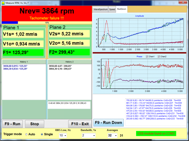
Fig. 7.8. Vibration meter mode. Rotation speed Unevenness, 1x vibration wave form.
Fig. 7.9. Vibration meter mode. Rundown (beta version, no warranty!).
7.3 Балансировка рәсімі
Balancing is performed for mechanisms in good technical condition and correctly mounted. Otherwise, before the balancing the mechanism must be repaired, installed in proper bearings and fixed. Rotor should be cleaned of contaminants that can hinder from balancing procedure.
Before balancing measure vibration in Vibration meter mode (F5 button) to be sure that mainly vibration is 1x vibration.
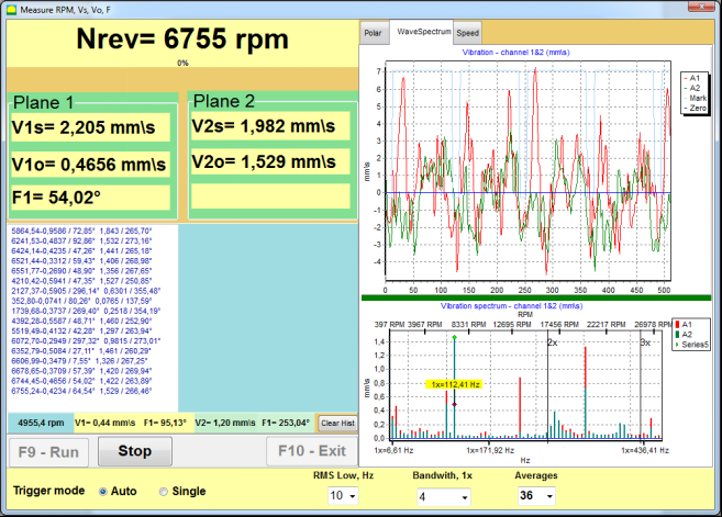
Fig. 7.10. Vibration meter mode. Checking overall (V1s,V2s) and 1x (V1o,V2o) vibration.
Егер жалпы дірілдің V1s (V2s) мәні айналу жиілігіндегі дірілдің шамасына (1x дірілі) V1o (V2o) шамамен тең болса, механизмнің діріліне негізгі үлес ротордың дисбалансынан келеді деп болжауға болады. Егер жалпы дірілдің V1s (V2s) мәні 1x дірілі компонентінен V1o (V2o) едәуір жоғары болса, механизм жағдайын тексеру ұсынылады — мойынтіректердің жағдайы, негізге бекіту сенімділігі, айналу кезінде бекітілген бөліктер мен ротордың жанасу мүмкіндігін болдырмау және т.б.
You should also pay attention to the stability of the measured values in Vibration meter mode – the amplitude and phase of the vibration should not vary by more than 10-15% in the measurement process. Otherwise, it can be assumed that the mechanism is running close-to-resonance domain. In this case, change the speed of rotation of the rotor, and if this is not possible – change the conditions of installation of the machine on the foundation (for example, temporarily setting on spring supports).
Ротор балансировкасы үшін ықпал коэффициенттері әдісі балансировка тәсілі (3 жүрістік әдіс) қолданылуы тиіс.
Trial runs are done to determine the effect of trial mass on vibration change, mass and place (angle) of installation of correction weights.
First determine the original vibration of a mechanism (first start without weight), and then set the trial weight to the first plane and made the second start. Then, remove the trial weight from the first plane, set in a second plane and made the second start.
The program then calculates and indicates on the screen the weight and location (angle) of installation of correction weights.
When balancing in a single plane (static), the second start is not required.
Trial weight is set to an arbitrary location on the rotor where it is convenient, and then the actual radius is entered in the setup program.
(Position Radius is used only for calculating the unbalance amount in grams * mm)
Маңызды!
- Measurements should be carried out with the constant speed of rotation of the mechanism!
- Correction weights must be installed on the same radius as the trial weights!
Mass of the trial weight is selected so that after its installation phase (> 20-30°) and (20-30%) the amplitude of vibration change significantly. If changes are too small, the error increases greatly in subsequent calculations. Conveniently set trial mass at the same place (the same angle) as the phase mark.
Сынақ салмағы массасын есептеу формуласы
Mt = Mr × Ksupport × Kvibration / (Rt × (N/100)²)
Where:
- Mt — сынақ салмағының массасы, г
- Mr — ротор массасы, г
- Ksupport — тіреу қаттылығының коэффициенті (1-5)
- Kvibration — дірілдің деңгей коэффициенті (0,5–2,5)
- Rt — сынақ салмағын орнату радиусы, см
- N — ротордың айналу жиілігі, айн/мин
Тіреу қаттылығы коэффициенті (Ктіреу):
- 1.0 - өте жұмсақ тіреулер (резеңке демпферлер)
- 2.0-3.0 - орташа қаттылық (стандартты мойынтіректер)
- 4.0-5.0 - қатты тіреулер (массивті іргетас)
Дірілдің деңгей коэффициенті (Кдіріл):
- 0.5 — Төмен діріл (5 мм/с дейін)
- 1.0 — Қалыпты діріл (5–10 мм/с)
- 1.5 — Жоғарылаған діріл (10–20 мм/с)
- 2.0 — Жоғары діріл (20–40 мм/с)
- 2.5 — Өте жоғары діріл (>40 мм/с)
🔗 Онлайн калькуляторымызды пайдаланыңыз:
Сынақ салмағы калькуляторы →⚠️ Important!
After each test run trial mass are removed! Correction weights set at an angle calculated from the place of trial weight installation in the direction of rotation of the rotor!
Бұрышты есептеуге түсінік:
Түзету салмағын орнату бұрышы: ALWAYS ротордың айналу бағытында сынақ салмағын орнату нүктесінен есептеледі.
- Нөлдік нүкте (0°): Сынақ салмағын орнатқан дәл орын анықтамалық нүктеңізге (0 градус) айналады.
- Direction: Бұрышты ротордың айналу бағытымен өлшеңіз.
Мысалы: ротор сағат тілімен айналса, бұрышты сынақ салмағының орнынан сағат тілімен өлшеңіз. - Interpretation: Бағдарлама бұрышты көрсетсе: 120°, түзету салмағын орнатуыңыз қажет 120 градус алға айналу бағытында сынақ салмағының орнынан.
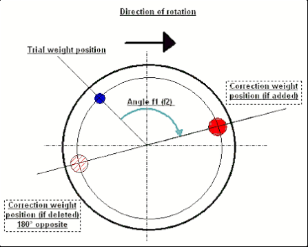
Fig. 7.11. Correction weight mounting.
Recommended!
Before performing dynamic balancing, it is recommended to make sure that static imbalance is not too high. For rotors with horizontal axis, the rotor can be manually rotated by an angle of 90 degrees from the current position. If the rotor is statically unbalanced, it will be rotated to a position of equilibrium. Once the rotor will assume the position of equilibrium, it is necessary to set the weight balancing in the top point approximately in the middle part of the rotor length. Weight of the weight should be chosen in such a way that the rotor is not moving in any position.
Such pre-balancing will reduce the amount of vibration at the first start of strongly unbalanced rotor.
Датчикті орнату және бекіту
Вibration sensor must be installed on the machine in the selected measuring point and connected to the input X1 of the USB interface unit.
Екі бекіту конфигурациясы бар:
- Magnets
- Threaded studs M4
Optical tacho sensor should be connected to the input X3 of the USB interface unit. Furthermore, for use of this sensor a special reflecting mark should be applied on surface of a rotor.
📏 Оптикалық датчикті орнатуға қойылатын талаптар
- ✓Ротор бетіне дейінгі қашықтық: 50-500 мм (датчик моделіне байланысты)
- ✓Шағылыстырғыш лентаның ені: Кемінде 1-1,5 см (жылдамдық пен радиусқа байланысты)
- ✓Orientation: Ротор бетіне перпендикуляр
- ✓Mounting: Тұрақты орналасу үшін магниттік тіреуіш немесе қысқыш қолданыңыз
- ✓Тікелей күн сәулесінен аулақ болыңыз немесе сенсорға/таспаға түскен қатты жасанды жарық
💡 Таспа енін есептеу: Оңтайлы жұмыс үшін таспа енін келесі формула арқылы есептеңіз:
L ≥ (N × R)/30000 ≥ 1.0-1.5 cm
Мұнда: L — таспа ені (см), N — ротор айналу жиілігі (айн/мин), R — таспа радиусы (см)
Detailed requirements on site selection of the sensors and their attachment to the object when balancing are set out in Annex 1.
7.4 Бір жазықтықта теңгерімдеу
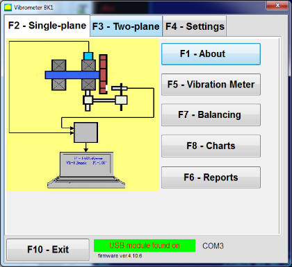
Сур. 7.12. "Бір жазықтықта балансирлау"
Теңгерімдеу мұрағаты
Бағдарламада "Single-Plane balancing" режимінде жұмысты бастау үшін "F2-Single-plane" түймесін басыңыз (немесе компьютер пернетақтасындағы F2 пернесін басыңыз).
Содан кейін "F7 – Balancing" түймесін басыңыз, осыдан кейін Single Plane balancing archive window will appear, in which the balancing data will be saved (see Fig. 7.13).

Fig. 7.13 The window for selecting the balancing archive in single plane.
In this window, you need to enter data on the name of the rotor (Rotor name), place of rotor installation (Place), tolerances for vibration and residual imbalance (Tolerance), date of measurement. This data is stored in a database. Also, a folder Arc### is created in, where ### is the number of the archive in which the charts, a report file, etc. will be saved. After the balancing is completed, a report file will be generated that can be edited and printed in the built-in editor.
After entering the necessary data, you need to click the “F10-OK" түймесін басыңыз, осыдан кейін "Single-Plane balancing" терезесі ашылады (7.13-суретті қараңыз)
Balancing settings (1-plane)
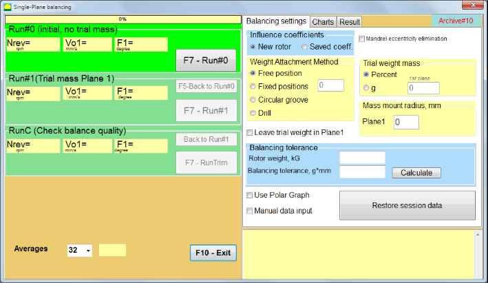
Fig. 7.14. Single plane. Balancing settings
Бұл терезенің сол жағында діріл өлшеулерінің деректері және өлшеуді басқару түймелері "Run # 0", "Run # 1", "RunTrim".
In the right side of this window there are three tabs
- Balancing settings
- Charts
- Result
The "Balancing settings" қойындысы теңгерімдеу параметрлерін енгізу үшін қолданылады:
- "Ықпал ету коэффициенті" -
- "New Rotor” – selection of the balancing of the new rotor, for which there are no stored balancing coefficients and two runs are required to determine the mass and installation angle of the correction weight.
- "Saved coeff.” – selection of the rotor re-balancing, for which there are saved balancing coefficients and only one run is required for determining the weight and installation angle of the corrective weight.
- "Сынақ салмағының массасы" -
- "Percent" — түзету салмағы сынақ салмағының пайызы ретінде есептеледі.
- "Gram" — сынақ салмағының белгілі массасы енгізіледі және түзету салмағының массасы есептеледі grams or in oz for Imperial system.
⚠️ Attention! Егер "Saved coeff.” Mode for further work during initial balancing, the trial weight mass must be entered in grams or oz, not in %. Scales are included in the delivery package.
- "Салмақты бекіту әдісі"
- "Free position" - салмақтарды ротордың шеңбері бойынша кез келген бұрыштық орынға орнатуға болады.
- "Fixed position” – weight can be installed in fixed angular positions on the rotor, for example, on blades or holes (for example 12 holes – 30 degrees), etc. The number of fixed positions must be entered in the appropriate field. After balancing, the program will automatically split the weight into two parts and indicate the number of positions on which it is necessary to establish the masses obtained.
- "Circular groove" – тегістеу дөңгелегін теңгеруге арналған. Бұл жағдайда теңгерімсіздікті жою үшін 3 қарсы салмақ қолданылады
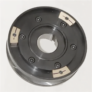
Fig. 7.17 Grinding wheel balancing with 3 counterweights
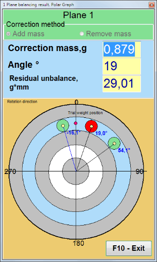
Fig. 7.18 Grinding wheel balancing. Polar graph.

Fig. 7.15. Result tab. Fixed position of correction weight mounting.
Z1 және Z2 – орнатылған түзету салмақтарының орындары, айналу бағытына сәйкес Z1 орнынан есептеледі. Z1 – сынақ салмағы орнатылған орын.
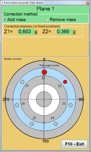
Fig. 7.16 Fixed positions. Polar diagram.
- "Mass mount radius, mm" - "Plane1" - 1-жазықтықтағы сынақ салмағының радиусы. Теңгерулеуден кейін қалдық теңгерімсіздіктің рұқсат етілген мәнге сәйкестігін анықтау үшін бастапқы және қалдық теңгерімсіздіктің шамасын есептеу қажет.
- "Leave trial weight in Plane1.” Usually the trial weight is removed during the balancing process. But in some cases it is impossible to remove it, then you need to set a check mark in this to account for the trial weight mass in the calculations.
- "Manual data input” – used to manually enter the vibration value and phase into the appropriate fields on the left side of the window and calculate the mass and installation angle of the correction weight when switching to the “Results" tab
- Button "Restore session data“. During balancing, the measured data is saved in the session1.ini file. If the measurement process was interrupted due to computer freezing or for other reasons, then by clicking this button you can restore the measurement data and continue balancing from the moment of interruption.
- Mandrel eccentricity elimination (Index balancing) Balancing with additional start to eliminate the influence of the eccentricity of the mandrel (balancing arbor). Mount the rotor alternately at 0° and 180° relative to the. Measure the unbalances in both positions.
- Balancing tolerance Entering or calculating residual imbalance tolerances in g x mm (G-classes)
- Use Polar Graph Use polar graph to display balancing results
1-plane Balancing. New rotor
Жоғарыда атап өтілгендей, "New Rotor" теңгерулеу балансировка машинасының екі сынақ жүрісін және кемінде бір түзету жүрісін қажет етеді.
Run#0 (Initial run)
After installing the sensors on the balancing rotor and entering the settings parameters, it is necessary to turn on the rotor rotation and, when it reaches working speed, press the “Run#0" өлшеуді бастау үшін түймені басыңыз. "Charts" қосымша беті оң панельде ашылады, онда тербеліс толқын пішіні мен спектрі көрсетіледі. Қосымша беттің төменгі бөлігінде уақыт белгісі бар барлық іске қосулардың нәтижелері сақталатын тарих файлы орналасқан. Дискіде бұл файл мұрағат қалтасына memo.txt атауымен сақталады
Attention!
Before starting the measurement, it is necessary to turn on the rotation of the rotor of the balancing machine (Run#0) and make sure that the rotor speed is stable.
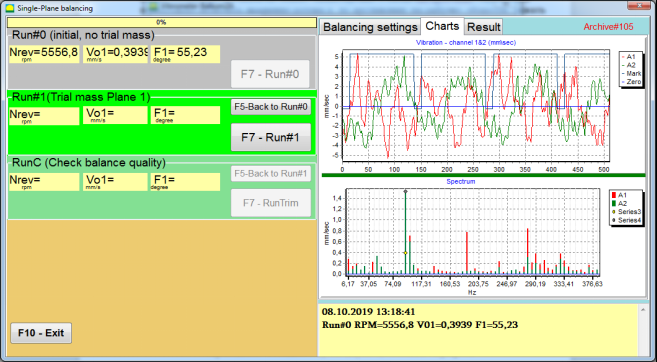
Fig. 7.19. Balancing in one plane. Initial run (Run#0). Charts Tab
After measurement process finished, in the Run#0 сол панельдің бөлімінде өлшеу нәтижелері пайда болады – ротордың айналу жиілігі (RPM), 1x тербелісінің СКМ мәні (Vo1) және фазасы (F1).
The "F5-Back to Run#0” button (or the F5 function key) is used to return to the Run#0 section and, if necessary, to repeat measure the vibration parameters.
Run#1 (Trial mass Plane 1)
"" бөліміндегі тербеліс параметрлерін өлшеуді бастамас бұрынRun#1 (Trial mass Plane 1), сынақ салмағын "" бойынша орнату қажетTrial weight mass" field.
The goal of installing a trial weight is to evaluate how the vibration of the rotor changes when a known weight is installed at a known place (angle). Trial weight must changes the vibration amplitude by either 30% lower or higher of initial amplitude or change phase by 30 degrees or more of initial phase.
Егер "Saved coeff.” balancing for further work, the place (angle) of installation of the trial weight must be the same as the place (angle) of the reflective mark.
Turn on the rotation of the rotor of the balancing machine again and make sure that it rotation frequency is stable. Then click on the “F7-Run#1" түймесін басыңыз (немесе компьютер пернетақтасындағы F7 пернесін басыңыз).
"" бөлімінің тиісті терезелерінде өлшеуден кейінRun#1 (Trial mass Plane 1)" бөлімінде ротордың айналу жиілігінің (RPM) өлшеу нәтижелері, сондай-ақ 1x тербелісінің СКМ компонентінің мәні (Vо1) және фазасы (F1) пайда болады.
Сонымен бірге, "Result" қосымша беті терезенің оң жағында ашылады.
This tab displays the results of calculating the mass and angle of corrective weight, which must be installed on the rotor to compensate imbalance.
Moreover, in the case of using the polar coordinate system, the display shows the value of the mass (M1) and the installation angle (f1) of the correction weight.
"" жағдайындаFixed positions” the numbers of the positions (Zi, Zj) and trial weight splitted mass will be shown.
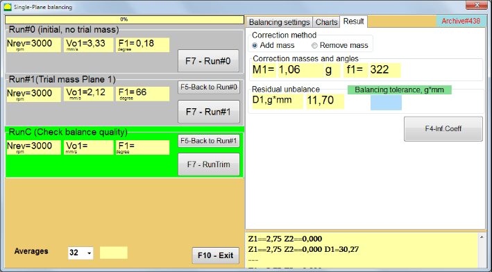
Fig. 7.20. Balancing in one plane. Run#1 and balancing result.
If Polar graph is checked polar diagram will be shown.
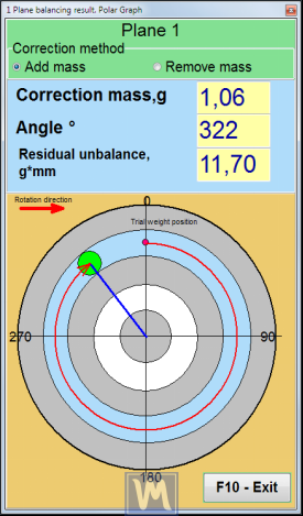
Fig. 7.21. The result of balancing. Polar graph.
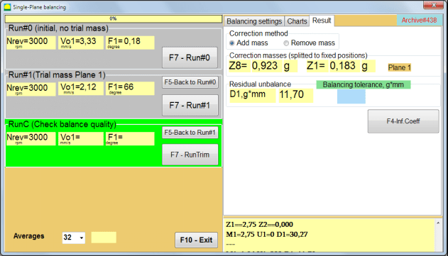
Fig. 7.22. The result of balancing. Weight splitted (fixed positions)
Also if "Polar graph" белгіленген болса, полярлық график көрсетіледі.
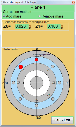
Fig. 7.23. Weight splitted on fixed positions. Polar graph
⚠️ Attention!
- 1. After completing the measurement process at the second run (“Run#1 (Trial mass Plane 1)”) of the balancing machine, it is necessary to stop the rotation and remove installed trial weight. Then install (or remove) the corrective weight on the rotor according result tab data.
If the trial weight was not removed, you need to switch to the “Balancing settings" қосымша бетіне өтіп, "Leave trial weight in Plane1". Содан кейін "Result” tab. The weight and installation angle of the correction weight are recalculated automatically.
- Түзету салмағының бұрыштық орны сынақ салмағын орнату орнынан белгіленеді. Бұрышты есептеу бағыты ротордың айналу бағытымен сәйкес келеді.
- "" жағдайындаFixed position" - the 1st position (Z1), coincides with the place of installation of the trial weight. The counting direction of the position number is in the direction of rotation of the rotor.
- Әдепкі бойынша түзету салмағы ротorға қосылады. Бұл "Add" өрісіндегі белгімен көрсетіледі. Егер салмақты алып тастасаңыз (мысалы, бұрғылау арқылы), "Delete” field, after which the angular position of the correction weight will automatically change by 180º.
After installing the correction weight on the balancing rotor in the operating window (see Fig. 7.15), it is necessary to carry out a RunC (trim) and evaluate the effectiveness of the performed balancing.
RunC (Check balance quality)
⚠️ Attention! Before starting the measurement on the RunC, it is necessary to turn on the rotation of the rotor of the machine and make sure that it has entered the operating mode (stable rotation frequency).
"RunC (Check balance quality)" бөліміндегі дірілді өлшеу үшін "F7 – RunTrim" түймесін басыңыз (немесе пернетақтадағы F7 пернесін басыңыз).
Өлшеу процесі сәтті аяқталғаннан кейін "RunC (Check balance quality)" бөліміндегі сол панельде ротор айналу жиілігінің (айн/мин) өлшеу нәтижелері, сондай-ақ 1x дірілдің СКО мәні (Vo1) мен фазасы (F1) пайда болады.
In the "Result” tab, the results of calculating the mass and installation angle of the additional corrective weight are displayed.
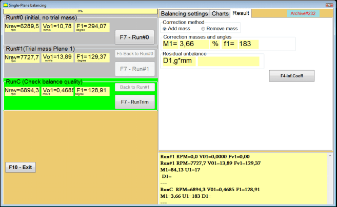
Fig. 7.24. Balancing in one plane. Performing a RunTrim. Result Tab
This weight can be added to the correction weight that is already mounted on the rotor to compensate for the residual imbalance. In addition, the residual rotor unbalance achieved after balancing is displayed in the lower part of this window.
In the case when the amount of residual vibration and / or residual unbalance of the balanced rotor meets the tolerance requirements established in the technical documentation, the balancing process can be completed.
Otherwise, the balancing process may continue. This allows the method of successive approximations to correct possible errors that may occur during the installation (removal) of the corrective weight on a balanced rotor.
When continuing the balancing process on the balancing rotor, it is necessary to install (remove) additional corrective mass, the parameters of which are indicated in the section “Correction masses and angles".
Influence coefficients (1-plane)
The "F4-Inf.Coeff" бөліміндегі "Result" қойындысы калибрлеу жүрістерінің нәтижелері бойынша есептелген ротор балансировкасының коэффициенттерін (әсер ету коэффициенттерін) қарап шығу және компьютер жадына сақтау үшін қолданылады.
Оны басқанда компьютер дисплейінде "Influence coefficients (single plane)" терезесі ашылады, онда калибрлеу (сынақ) жүрістерінің нәтижелері бойынша есептелген балансировка коэффициенттері көрсетіледі. Егер осы машинаның кейінгі балансировкасында "Saved coeff.” Mode, these coefficients must be stored in the computer memory.
Мұны орындау үшін "F9 - Save" түймесін басып, "Әсер ету коэф. мұрағаты. Бір жазықтықта."

Fig. 7.25. Balancing coefficients in the 1st plane
Then you need to enter the name of this machine in the “Rotor" бағанасына өтіп, "F2-Save” button to save the specified data on the computer.
Then you can return to the previous window by pressing the “F10-Exit" түймесін басыңыз (немесе компьютер пернетақтасындағы F10 функционалдық пернесін басыңыз).
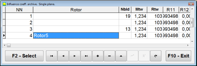
Сур. 7.26. "Әсер ету коэф. мұрағаты. Бір жазықтықта."
Balancing report
After balancing all data saved and Balancing report created. You can view and edit report in built-in editor. In the "Бір жазықтықта балансировка мұрағаты" (Сур. 7.9) "F9 -Report" түймесін басып теңгерімдеу есебінің редакторына өтіңіз.
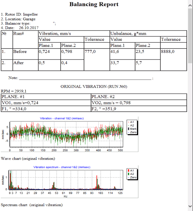
Сур. 7.27. Теңгерімдеу есебі.
Saved coeff. balancing procedure with saved influence coefficients in 1 plane.
Setting up the measuring system (input of initial data).
Saved coeff. balancing can be performed on a machine for which balancing coefficients have already been determined and entered into the computer memory.
⚠️ Attention! When balancing with saved coefficients, the vibration sensor and the phase angle sensor must be installed in the same way as during the initial balancing.
Input of the initial data for Saved coeff. balancing (бастапқы ("New rotor") теңгерімдеу жағдайындағыдай) "Single plane balancing. Balancing settings.".
Бұл жағдайда "Influence coefficients" бөлімінен "Saved coeff" элементін таңдаңыз. Бұл жағдайда "Influence coeff. archive. Single plane." бетінде сақталған теңгерімдеу коэффициенттері мұрағаты орналасқан.
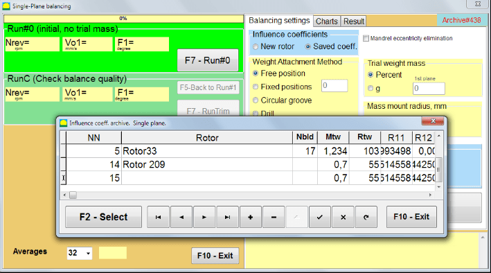
Fig. 7.28. Balancing with saved influence coefficients in 1 plane
«►» немесе «◄» басқару түймелерін пайдаланып осы мұрағат кестесі арқылы жылжып, бізді қызықтыратын машинаның теңгерімдеу коэффициенттері бар қажетті жазбаны таңдауға болады. Содан кейін бұл деректерді ағымдағы өлшеулерде пайдалану үшін "F2 – Select" button.
After that, the contents of all other windows of the “Single plane balancing. Balancing settings." өрістері автоматты түрде толтырылады.
After completing the input of the initial data, you can begin to measure.
Сақталған ықпал коэффициенттерімен теңгерімдеу кезіндегі өлшеулер
Balancing with saved influence coefficients requires only one initial run and at least one test run of the balancing machine.
⚠️ Attention! Before starting the measurement, it is necessary to turn on the rotation of the rotor and make sure that rotating frequency is stable.
"Run#0 (Initial, no trial mass)" бөлімінде дірілдің параметрлерін өлшеуді жүргізу үшін "F7 – Run#0" түймесін басыңыз (немесе компьютер пернетақтасындағы F7 пернесін басыңыз).
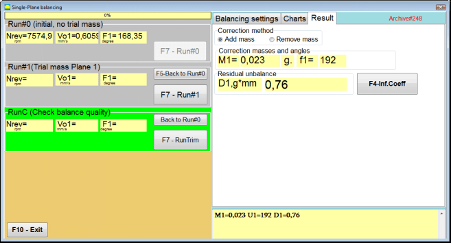
Fig. 7.29. Balancing with saved influence coefficients in one plane. Results after one run.
"Run#0" бөлімінің тиісті өрістерінде ротордың айналу жиілігін (айн/мин), 1x дірілдің СКШ компонентінің мәні (Vо1) және фазасы (F1) өлшеу нәтижелері пайда болады.
Сонымен бірге, "ResultThis tab displays the results of calculating the mass and angle of corrective weight, which must be installed on the rotor to compensate imbalance.
Сонымен қатар, полярлық координаттар жүйесін пайдаланған жағдайда, дисплейде түзету жүктерінің массалары мен орнату бұрыштары көрсетіледі.
In the case of splitting of the corrective weight on the fixed positions, the numbers of the positions of the balancing rotor and the mass of weight that need to be installed on them are displayed.
Further, the balancing process is carried out in accordance with the recommendations set out in section 7.4.2. for primary balancing.
Mandrel eccentricity elimination (Index balancing)
If during balancing the rotor is installed in a cylindrical mandrel, then the eccentricity of the mandrel may introduce an additional error. To eliminate this error, the rotor should be deployed in the mandrel 180 degrees and carry out an additional start. This is called index balancing.
To carry out index balancing, a special option is provided in the Balanset-1A program. When checked Mandrel eccentricity elimination an additional RunEcc section appears in the balancing window.

Fig. 7.30. The working window for Index balancing.
After running Run # 1 (Trial mass Plane 1), a window will appear
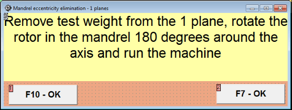
Fig. 7.31 Index balancing attention window.
After installing the rotor with an 180 turn, Run Ecc must be completed. The program will automatically calculate the true rotor imbalance without affecting the mandrel eccentricity.
7.5 Екі жазықтықта теңгерімдеу
Before starting work in the Two plane balancing mode, it is necessary to install vibration sensors on the machine body at the selected measurement points and connect them to the inputs X1 and X2 of the measuring unit, respectively.
An optical phase angle sensor must be connected to input X3 of the measuring unit. In addition, to use this sensor, a reflective tape must be glued onto the accessible rotor surface of the balancing machine.
Detailed requirements for choosing the installation location of sensors and their mounting at the facility during balancing are set out in Appendix 1.
Бағдарламамен "Two plane balancing" режимі бағдарламалардың Негізгі терезесінен басталады.
Click on the "F3-Two plane" түймесін басыңыз (немесе компьютер пернетақтасындағы F3 пернесін басыңыз).
Further, click on the “F7 – Balancing” button, after which a working window will appear on the computer display (see Fig. 7.13), selection of the archive for saving data when balancing in two p
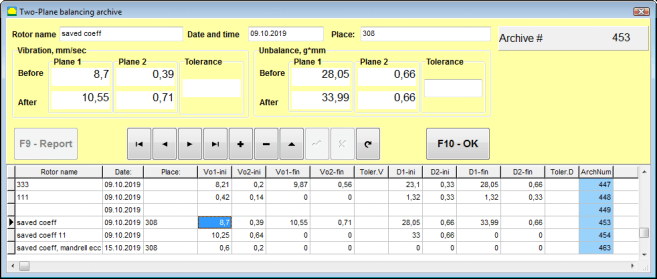
Fig. 7.32 Two plane balancing archive window.
In this window you need to enter the data of the balanced rotor. After pressing the “F10-OK" түймесін басқаннан кейін теңгерімдеу терезесі пайда болады.
Balancing settings (2-plane)
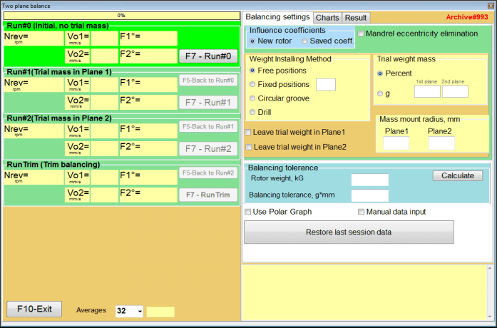
Fig. 7.33. Balancing in two planes window.
Терезенің оң жағында "Balancing settings" қойындысы теңгерімдеуден бұрын параметрлерді енгізу үшін орналасқан.
- Influence coefficients Balancing a new rotor or balancing using stored influence coefficients (balancing coefficients)
- Mandrel eccentricity elimination - Оправканың эксцентриситетінің әсерін жою үшін қосымша іске қосумен теңгерімдеу
- Weight Attachment Method Installation of corrective weights in an arbitrary place on the circumference of the rotor or in a fixed position. Calculations for drilling when removing the mass.
- "Free position" - салмақтарды ротордың шеңбері бойынша кез келген бұрыштық орынға орнатуға болады.
- "Fixed position” – weight can be installed in fixed angular positions on the rotor, for example, on blades or holes (for example 12 holes – 30 degrees), etc. The number of fixed positions must be entered in the appropriate field. After balancing, the program will automatically split the weight into two parts and indicate the number of positions on which it is necessary to establish the masses obtained.
- Trial weight mass - Trial weight
- Leave trial weight in Plane1 / Plane2 - Теңгерімдеу кезінде сынақ салмағын алып тастау немесе қалдыру.
- Mass mount radius, mm - Сынақ және түзету салмақтарын орнату радиусы
- Balancing tolerance Entering or calculating residual imbalance tolerances in g-mm
- Use Polar Graph - Теңгерімдеу нәтижелерін көрсету үшін полярлық графикті пайдалану
- Manual data input - Теңгерімдеу салмақтарын есептеу үшін деректерді қолмен енгізу
- Restore last session data - Теңгерімдеуді жалғастыру мақсатында ақаулық болған жағдайда соңғы сеанстың өлшеу деректерін қалпына келтіру.
2 planes balancing. New rotor
Setting up the measuring system (input of initial data).
Input of the initial data for the New rotor balancing in the "Екі жазықтықта теңгерімдеу. Параметрлер".
Бұл жағдайда "Influence coefficients" бөлімінен "New rotor" item.
Одан әрі, "Trial weight mass" бөлімінде сынақ салмағының массасын өлшеу бірлігін таңдау қажет — "Gram" or "Percent".
" өлшем бірлігін таңдаған кездеPercent”, all further calculations of the mass of the corrective weight will be performed as a percentage in relation to the mass of the trial weight.
" таңдаған кездеGram” unit of measurement, all further calculations of the mass of the corrective weight will be performed in grams. Then enter in the windows located to the right of the inscription “Gram" роторға орнатылатын сынақ салмақтарының массасы.
⚠️ Attention! Егер "Saved coeff.” Mode for further work during initial balancing, the mass of trial weights must be entered in grams.
Then select "Weight Attachment Method" - "Circum" or "Fixed position".
Егер " таңдасаңызFixed position", позициялар санын енгізу қажет.
Calculation of tolerance for residual imbalance (Balancing tolerance)
Қалдық дисбаланс төзімділігін (теңгерімдеу төзімділігі) ISO 1940 Тербеліс стандартында сипатталған әдіске сәйкес есептеуге болады. Тұрақты (қатты) күйдегі роторлардың теңгерімдеу сапасына қойылатын талаптар. 1-бөлім. Теңгерімдеу төзімділіктерін анықтау және тексеру.

Fig. 7.34. Balancing tolerance calculation window
Initial run (Run#0)
Екі жазықтықта теңгерімдеу кезінде "New rotor” mode, balancing requires three calibration runs and at least one test run of the balancing machine.
Машинаның бірінші іске қосылуындағы тербеліс өлшеуі "Two plane balance" жұмыс терезесінде "Run#0" section.
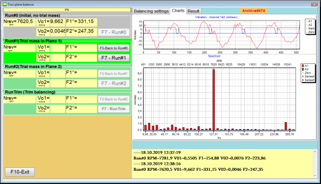
Сур. 7.35. Бастапқы жүргізуден кейін екі жазықтықта теңгерімдеу нәтижелері.
⚠️ Attention! Before starting the measurement, it is necessary to turn on the rotation of the rotor of the balancing machine and make sure that it has entered the operating mode with a stable speed.
To measure vibration parameters in the Run#0 бөлімінде "F7 – Run#0" түймесін басыңыз (немесе компьютер пернетақтасындағы F7 пернесін басыңыз)
The results of measuring the rotor speed (RPM), the value RMS (VО1, VО2) and phases (F1, F2) of 1x vibration appearing appear in the corresponding windows of the Run#0 section.
Run#1.Trial mass in Plane1
"Run#1.Trial mass in Plane1” section, you should stop the rotation of the rotor of the balancing machine and install a trial weight on it, the mass selected in the “Trial weight mass" section.
⚠️ Attention!
- 1. The question of choosing the mass of trial weights and their installation places on the rotor of a balancing machine is discussed in detail in Appendix 1.
- Егер пайдалану қажет болса Saved coeff. Mode in future work, the place for installing the trial weight must necessarily coincide with the place for installing the mark used to read the phase angle.
After this, it is necessary to turn on the rotation of the rotor of the balancing machine again and make sure that it has entered the operating mode.
"Run # 1.Trial mass in Plane1" бөліміндегі дірілді өлшеу үшін "F7 – Run#1" түймесін басыңыз (немесе компьютер пернетақтасындағы F7 пернесін басыңыз).
Өлшеу процесі сәтті аяқталған соң, өлшеу нәтижелері қойындысына ораласыз.
Бұл жағдайда "Run#1. Trial mass in Plane1” section, the results of measuring the rotor speed (RPM), as well as the value of the components of the RMS (Vо1, Vо2) and phases (F1, F2) of 1x vibration.
"Жүріс № 2. 2-жазықтықтағы сынақ масса"
"Run # 2.Trial mass in Plane2", келесі қадамдарды орындау қажет:
- теңгерімдеу машинасы роторының айналуын тоқтату;
- 1-жазықтықта орнатылған сынақ салмақты алып тастау;
- 2-жазықтыққа сынақ салмақ орнату, масса "Trial weight mass".
After this, turn on the rotation of the rotor of the balancing machine and make sure that it has entered the operating speed.
"Run # 2.Trial mass in Plane2" бөліміндегі дірілді өлшеу үшін "F7 – Run # 2" түймесін басыңыз (немесе компьютер пернетақтасындағы F7 пернесін басыңыз). Содан кейін "Result" tab opens.
In the case of using the Weight Attachment Method" - "Free positions, дисплейде түзету салмақтарының масса мәндері (M1, M2) және орнату бұрыштары (f1, f2) көрсетіледі.
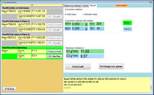
Fig. 7.36. Results of calculation of corrective weights – free position
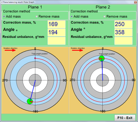
Сур. 7.37. Түзету салмақтарын есептеу нәтижелері — бос орын. Полярлық диаграмма
In the case of using the Weight Attachment Method" – "Fixed positions

Сур. 7.38. Түзету салмақтарын есептеу нәтижелері – бекітілген орын.
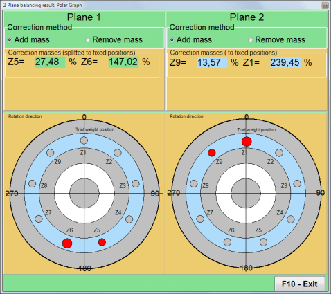
Сур. 7.39. Түзету салмақтарын есептеу нәтижелері – бекітілген орын. Полярлық диаграмма.
«Салмақты бекіту әдісін» пайдаланған жағдайда – «Circular groove"
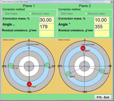
Сур. 7.40. Түзету салмақтарын есептеу нәтижелері – дөңгелек жұлдырма.
⚠️ Attention!
- Өлшеу процесін аяқтағаннан кейін RUN#2 of the balancing machine, stop the rotation of the rotor and remove the trial weight previously installed. Then you can to install (or remove) corrective weights.
- Полярлық координаттар жүйесіндегі түзету салмақтарының бұрыштық орны сынақ салмағын орнату нүктесінен ротордың айналу бағытында есептеледі.
- "" жағдайындаFixed position" - the 1st position (Z1), coincides with the place of installation of the trial weight. The counting direction of the position number is in the direction of rotation of the rotor.
- Әдепкі бойынша түзету салмағы ротorға қосылады. Бұл "Add" өрісіндегі белгімен көрсетіледі. Егер салмақты алып тастасаңыз (мысалы, бұрғылау арқылы), "Delete” field, after which the angular position of the correction weight will automatically change by 180º.
RunC (Trim run)
After installing the correction weight on the balancing rotor it is necessary to carry out a RunC (trim) and evaluate the effectiveness of the performed balancing.
⚠️ Attention! Before starting the measurement at the test run, it is necessary to turn on the rotation of the rotor of the machine and make sure that it has entered the operating
RunTrim (Теңгерім сапасын тексеру) бөліміндегі тербеліс параметрлерін өлшеу үшін «F7 – RunTrim" түймесін басыңыз (немесе компьютер пернетақтасындағы F7 пернесін басыңыз).
The results of measuring the rotor rotation frequency (RPM), as well as the value of the RMS component (Vо1) and phase (F1) of 1x vibration will be shown.
The "Result» қосымша түзету салмақтарының параметрлерін есептеу нәтижелерін көрсететін өлшеу нәтижелері кестесі бар жұмыс терезесінің оң жағында қойынды пайда болады.
These weights can be added to corrective weights that are already installed on the rotor to compensate for residual imbalance.
In addition, the residual rotor unbalance achieved after balancing is displayed in the lower part of this window.
Теңгерімделген ротордың қалдық тербелісі және/немесе қалдық дисбалансының мәндері техникалық құжаттамада белгіленген рұқсат шектеріне сәйкес келетін жағдайда теңгерімдеу процесін аяқтауға болады.
Otherwise, the balancing process may continue. This allows the method of successive approximations to correct possible errors that may occur during the installation (removal) of the corrective weight on a balanced rotor.
When continuing the balancing process on the balancing rotor, it is necessary to install (remove) additional corrective mass, the parameters of which are indicated in the “Result” window.
In the "Result» терезесінде екі басқару түймесін пайдалануға болады – «F4-Inf.Coeff", "F5 – Change correction planes".
Influence coefficients (2 planes)
The "F4-Inf.Coeff» түймесі (немесе компьютер пернетақтасындағы F4 функционалдық пернесі) екі калибрлеу іске қосу нәтижелері бойынша есептелген ротор теңгерімдеу коэффициенттерін компьютер жадына қарап шығу және сақтау үшін пайдаланылады.
Оны басқанда компьютер дисплейінде "Influence coefficients (two planes)» жұмыс терезесі компьютер дисплейінде пайда болады, онда алғашқы үш калибрлеу іске қосу нәтижелері бойынша есептелген теңгерімдеу коэффициенттері көрсетіледі.

Fig. 7.41. Working window with balancing coefficients in 2 planes.
In the future, when balancing of such type of the machine it is supposed, require to use the “Saved coeff.» режимі және компьютер жадында сақталған теңгерімдеу коэффициенттері.
Коэффициенттерді сақтау үшін «F9 – Save» түймесін басып, «Influence coefficients archive (2planes)» терезелеріне өтіңіз (7.42-суретті қараңыз)
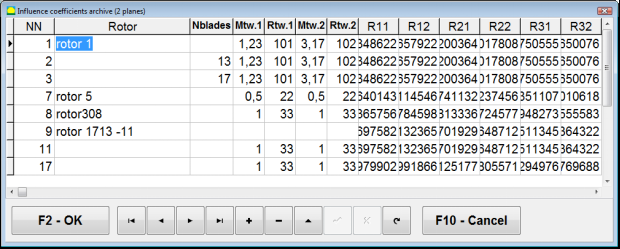
Fig. 7.42. The second page of the working window with balancing coefficients in 2 planes.
Change correction planes
The "F5 – Change correction planes» түймесі түзету жазықтықтарының орнын өзгерту қажет болғанда, яғни түзету салмақтарының массасы мен орнату бұрыштарын қайта есептеу керек болғанда пайдаланылады.
This mode is primarily useful when balancing rotors of complex shape (for example, crankshafts).
Осы түймені басқан кезде «Recalculation of correction weights mass and angle to other correction planes» компьютер дисплейінде көрсетіледі.
In this working window, you should select one of the 4 possible options by clicking corresponding picture.
The original correction planes (Н1 and Н2) in Fig. 7.29 are marked in green, and new (K1 and K2), for which it recounts, in red.
Then, in the "Calculation data» бөліміне сұралған деректерді енгізіңіз, соның ішінде:
- тиісті түзету жазықтықтары арасындағы қашықтық (a, b, c);
- роторда түзету салмақтарын орнатудың жаңа радиус мәндері (R1', R2').
Деректерді енгізгеннен кейін "F9-calculate"
The calculation results (masses M1, M2 and installation angles of corrective weights f1, f2) are displayed in the corresponding section of this working window (see Fig. 7.42).
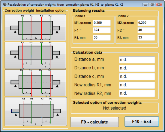
Сур. 7.43 Түзету жазықтықтарын өзгерту. Түзету массасы мен бұрышын басқа түзету жазықтықтарына қайта есептеу.
Сақталған коэфф. 2 жазықтықта теңгеру
Saved coeff. balancing can be performed on a machine for which balancing coefficients have already been determined and saved in the computer memory.
⚠️ Attention! When re-balancing, the vibration sensors and the phase angle sensor must be installed in the same way as during the initial balancing.
Қайта теңгеруге арналған бастапқы деректерді енгізу "2 жазықтықта теңгеру. Теңгеру параметрлері".
Бұл жағдайда "Influence coefficients" бөлімінен "Saved coeff." тармағынан басталады. Бұл жағдайда "Influence coefficients archive (2planes)" терезесі ашылады, онда бұрын анықталған теңгеру коэффициенттерінің мұрағаты сақталады.
«►» немесе «◄» басқару түймелерін пайдаланып осы мұрағат кестесі арқылы жылжып, бізді қызықтыратын машинаның теңгерімдеу коэффициенттері бар қажетті жазбаны таңдауға болады. Содан кейін бұл деректерді ағымдағы өлшеулерде пайдалану үшін "F2 – OK” button and return to the previous working window.
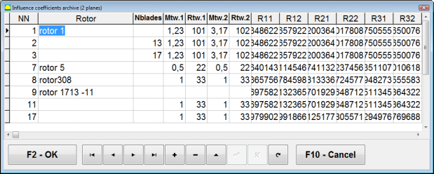
Fig. 7.44. The second page of the working window with balancing coefficients in 2 planes.
After that, the contents of all other windows of the “2 жазықт. теңгеру. Бастапқы деректер" автоматты түрде толтырылады.
Saved coeff. Balancing
"Saved coeff.” balancing requires only one tuning start and at least one test start of the balancing machine.
Vibration measurement at the tuning start (Run # 0) машинада "Balancing in 2 planes" жұмыс терезесінде теңгеру нәтижелерінің кестесімен орындалады, Run # 0 section.
⚠️ Attention! Before starting the measurement, it is necessary to turn on the rotation of the rotor of the balancing machine and make sure that it has entered the operating mode with a stable speed.
To measure vibration parameters in the Run # 0 бөлімінде "F7 – Run#0" түймесін басыңыз (немесе компьютер пернетақтасындағы F7 пернесін басыңыз).
The results of measuring the rotor speed (RPM), as well as the value of the components of the RMS (VО1, VО2) and phases (F1, F2) of the 1x vibration appear in the corresponding fields of the Run # 0 section.
Сонымен бірге, "Result" қойындысы ашылады, онда ротордың дисбалансын өтеу үшін орнатылуы тиіс түзету салмақтары параметрлерін есептеу нәтижелері көрсетіледі.
Бұдан басқа, полярлық координаталар жүйесін пайдаланған жағдайда дисплейде түзету салмақтарының масса мәндері мен орнату бұрыштары көрсетіледі.
In the case of decomposition of corrective weights on the blades, the numbers of the blades of the balancing rotor and the mass of weight that need to be installed on them are displayed.
Further, the balancing process is carried out in accordance with the recommendations set out in section 7.6.1.2. for primary balancing.
⚠️ Attention!
- After completion of the measurement process after the second start of the balanced machine stop the rotation of its rotor and remove the previously set trial weight. Only then you can begin to install (or remove) correction weight on the rotor.
- Counting the angular position of the place of adding (or removing) of the correction weight from the rotor is carried out on the installation site of trial weight in the polar coordinate system. Counting direction coincides with the direction of the angle of rotor rotation.
- Қалақшалар бойынша теңгеру жағдайында — 1-позиция ретінде белгіленген теңгерілетін ротор қалақшасы сынақ салмағын орнату орнымен сәйкес келеді. Дисплейде көрсетілген қалақша нөмірінің бағыты ротордың айналу бағытына сай орындалады.
- Бағдарламаның бұл нұсқасында әдепкі бойынша роторға түзету салмағы қосылады деп қабылданған. Мұны "Қосу" өрісіндегі белгі растайды. Салмақты алып тастау арқылы дисбалансты түзету жағдайында (мысалы, бұрғылау арқылы) "Алып тастау" өрісіне белгі қою қажет, сонда түзету салмағының бұрыштық орны автоматты түрде 180º-қа өзгереді.
Ілінгіш эксцентриситетін жою (Индекстік теңгеру) — Екі жазықтық
If during balancing the rotor is installed in a cylindrical mandrel, then the eccentricity of the mandrel may introduce an additional error. To eliminate this error, the rotor should be deployed in the mandrel 180 degrees and carry out an additional start. This is called index balancing.
To carry out index balancing, a special option is provided in the Balanset-1A program. When checked Mandrel eccentricity elimination an additional RunEcc section appears in the balancing window.
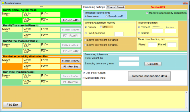
Fig. 7.45. The working window for Index balancing.
After running Run # 2 (Trial mass Plane 2), a window will appear
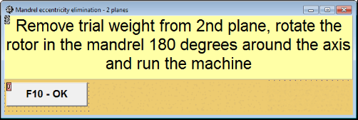
Fig. 7.46. Attention windows
After installing the rotor with an 180 turn, Run Ecc must be completed. The program will automatically calculate the true rotor imbalance without affecting the mandrel eccentricity.
7.6 Диаграммалар режимі
"Кестелер" режимінде жұмыс Бастапқы терезеден (7.1-суретті қараңыз) "F8 – Кестелер" түймесін басу арқылы басталады. Содан кейін "Екі арна бойынша діріл өлшеу. Кестелер" терезесі ашылады (7.19-суретті қараңыз).

7.47-сурет. "Екі арна бойынша діріл өлшеу. Кестелер" жұмыс терезесі.
While working in this mode it is possible to plot four versions of vibration chart.
The first version allows to get a timeline function of the overall vibration (of vibration velocity) on the first and second measuring channels.
The second version allows you to get graphs of vibration (of vibration velocity), which occurs on rotation frequency and its higher harmonical components.
These graphs are obtained as a result of the synchronous filtering of the overall vibration time function.
The third version provides vibration charts with the results of the harmonical analysis.
The fourth version allows to get a vibration chart with the results of the spectrum analysis.
Жалпы діріл кестелері
"Measurement of vibration on two channels. Charts" жұмыс терезесінде жалпы діріл кестесін тұрғызу үшін "overall vibration” by clicking the appropriate button. Then set the measurement of vibration in the box “Duration, in seconds,” by clicking on the button «▼» and select from the drop-down list the desired duration of the measurement process, which may be equal to 1, 5, 10, 15 or 20 seconds;
жұмыс режимін таңдау қажет. Дайын болғанда "F9"-Өлшеу" түймесін басыңыз (нұқыңыз), содан кейін екі арнада бір мезгілде діріл өлшеу процесі басталады.
After completion of the measurement process in the operating window appear charts of time function of the overall vibration of the first (red) and the second (green) channels (see. Fig. 7.47).
On these charts time is plotted on X-axis and the amplitude of the vibration velocity (mm/sec) is plotted on Y-axis.
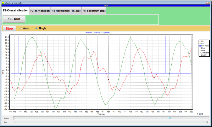
7.48-сурет. Жалпы діріл кестелерінің уақыт функциясын шығару жұмыс терезесі
There are also marks (blue-colored) in these graphs connecting charts of overall vibration with the rotation frequency of the rotor. In addition, each mark indicates beginning (end) of the next revolution of the rotor.
In need of the scale change of the chart on X-axis the slider, pointed by an arrow on fig. 7.20, can be used.
1x діріл кестелері
"Measurement of vibration on two channels. Charts" жұмыс терезесінде жалпы діріл кестесін тұрғызу үшін "1x vibration" жұмыс терезесінде 1x діріл кестесін тұрғызу үшін тиісті түймені басыңыз (нұқыңыз).
Содан кейін "1x діріл" жұмыс терезесі пайда болады.
"F9"-Өлшеу" түймесін басыңыз (нұқыңыз), содан кейін екі арнада бір мезгілде діріл өлшеу процесі басталады.
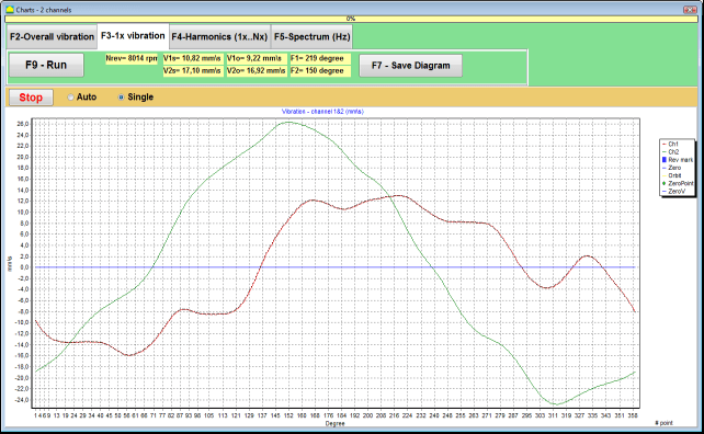
7.49-сурет. 1x діріл кестелерін шығару жұмыс терезесі.
After completion of the measurement process and mathematical calculation of results (synchronous filtering of the time function of the overall vibration) on display in the main window on a period equal to one revolution of the rotor appear charts of the 1x vibration on two channels.
In this case, a chart for the first channel is depicted in red and for the second channel in green. On these charts angle of the rotor revolution is plotted (from mark to mark) on X-axis and the amplitude of the vibration velocity (mm/sec) is plotted on Y-axis.
In addition, in the upper part of the working window (to the right of the button “F9 – Measure") екі арнаның діріл өлшемдерінің сандық мәндері көрсетіледі, олар "Vibration meter" режимінде алынатындарға ұқсас.
In particular: RMS value of the overall vibration (V1s, V2s), the magnitude of RMS (V1o, V2o) and phase (Fi, Fj) of the 1x vibration and rotor speed (Nrev).
Гармоникалық талдау нәтижелері бар діріл кестелері
"Measurement of vibration on two channels. Charts" жұмыс терезесінде жалпы діріл кестесін тұрғызу үшін "Harmonical analysis" жұмыс терезесінде 1x діріл кестесін тұрғызу үшін тиісті түймені басыңыз (нұқыңыз).
Then appears an operating window for simultaneous output of charts of temporary function and of spectrum of vibration harmonical aspects whose period is equal or multiple to the rotor rotation frequency (see Fig. 7.49)
Attention!
When operating in this mode it is necessary to use the phase angle sensor which synchronizes the measurement process with the rotor frequency of the machines to which the sensor is set.
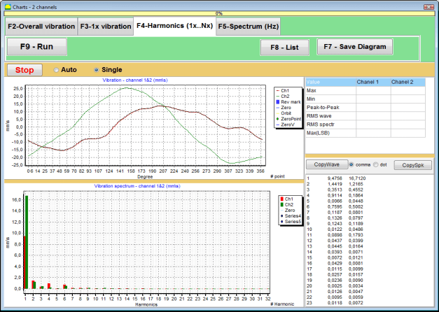
7.50-сурет. 1x діріл гармоникалары жұмыс терезесі.
жұмыс режимін таңдау қажет. Дайын болғанда "F9"-Өлшеу" түймесін басыңыз (нұқыңыз), содан кейін екі арнада бір мезгілде діріл өлшеу процесі басталады.
Өлшеу процесі аяқталғаннан кейін жұмыс терезесінде уақыттық функция графиктері (жоғарғы график) және 1x тербелістің гармоникалары (төменгі график) пайда болады.
The number of harmonic components is plotted on X-axis and RMS of the vibration velocity (mm/sec) is plotted on Y-axis.
Тербелістің уақыттық аймағы мен спектрінің графиктері
Спектр графигін салу үшін "F5-Spectrum" tab:
Содан кейін тербелістің толқындық және спектрлік графиктерін бір мезгілде шығаруға арналған жұмыс терезесі ашылады.

7.51-сурет. Тербеліс спектрін шығаруға арналған жұмыс терезесі.
жұмыс режимін таңдау қажет. Дайын болғанда "F9"-Өлшеу" түймесін басыңыз (нұқыңыз), содан кейін екі арнада бір мезгілде діріл өлшеу процесі басталады.
Өлшеу процесі аяқталғаннан кейін жұмыс терезесінде уақыттық функция графиктері (жоғарғы график) және тербеліс спектрі (төменгі график) пайда болады.
The vibration frequency is plotted on X-axis and RMS of the vibration velocity (mm/sec) is plotted on Y-axis.
In this case, a chart for the first channel is depicted in red and for the second channel in green.
General instructions on operation and maintenance of the device
8.1 Теңгерімдеу сапасының критерийлері (ISO 2372 стандарты)
Теңгерімдеу сапасын ISO 2372 стандартымен белгіленген тербеліс деңгейлері арқылы бағалауға болады. Төмендегі кестеде әр түрлі машина сыныптары үшін рұқсат етілген тербеліс деңгейлері көрсетілген:
| Machine Class | Жақсы (mm/sec RMS) |
Acceptable (mm/sec RMS) |
Әлі де жарамды (mm/sec RMS) |
Unacceptable (mm/sec RMS) |
|---|---|---|---|---|
| Class 1 Қатты іргетасқа орнатылған шағын машиналар (15 кВт-қа дейінгі электр қозғалтқыштар) |
< 0,7 | 0.7 - 1.8 | 1.8 - 4.5 | > 4.5 |
| Class 2 Іргетассыз орта машиналар (15–75 кВт электр қозғалтқыштар), 300 кВт-қа дейінгі жетек механизмдері |
< 1.1 | 1.1 - 2.8 | 2.8 - 7.1 | > 7.1 |
| Class 3 Қатты іргетасқа орнатылған ірі машиналар (300 кВт-тан жоғары жабдық) |
< 1,8 | 1.8 - 4.5 | 4.5 - 11 | > 11 |
| Class 4 Жеңіл іргетасқа орнатылған ірі машиналар (300 кВт-тан жоғары жабдық) |
< 2.8 | 2.8 - 7.1 | 7.1 - 18 | > 18 |
Ескерту: Бұл мәндер теңгерімдеу сапасын бағалауға бағыт береді. Нақты қолданбаңыз үшін әрдайым жабдық өндірушісінің техникалық шарттарына және қолданылатын стандарттарға жүгініңіз.
8.2 Техникалық қызмет көрсету талаптары
🔧 Жүйелі техникалық қызмет көрсету
- ✓Өндіруші нұсқаулығына сәйкес сенсорларды жүйелі калибрлеу
- ✓Сенсорларды таза ұстаңыз және магниттік қалдықтардан арылтыңыз
- ✓Жабдықты пайдаланбаған кезде қорғаушы қорапта сақтаңыз
- ✓Лазерлік сенсорды шаң мен ылғалдан қорғаңыз
- ✓Кабель қосылыстарын тозу немесе зақымдану белгілеріне тұрақты тексеріп отырыңыз
- ✓Бағдарламалық жасақтаманы өндіруші ұсынған мерзімде жаңартып отырыңыз
- ✓Маңызды балансировка деректерінің сақтық көшірмелерін сақтаңыз
📋 ЕО Техникалық қызмет көрсету стандарттары
Жабдықтың техникалық қызмет көрсетуі мына талаптарға сәйкес болуы тиіс:
- EN ISO 9001: Сапа менеджменті жүйелеріне қойылатын талаптар
- EN 13306: Техникалық қызмет көрсету терминологиясы мен анықтамалары
- EN 15341: Техникалық қызмет көрсетудің негізгі өнімділік көрсеткіштері
- ЕО машина жасау директивасына сәйкес тұрақты қауіпсіздік тексерулері
1-ҚОСЫМША. РОТОРДЫҢ БАЛАНСИРОВКАСЫ
Ротор — белгілі бір ось айналасында айналатын және тірек беттері арқылы тіреуіштерде ұсталатын дене. Ротордың тірек беттері ауырлықты тіреуіштерге домалақтау немесе сырғанау мойынтіректері арқылы береді. «Тірек беті» терминін қолданған кезде біз жай ғана мойынша* немесе мойынша алмастырушы беттерді айтамыз.
*Мойынша (неміс тілінде Zapfen — «мойынша», «білік») — білік немесе осьтің ұстағышта (мойынтірек қорабында) тіреледі тін бөлігі.
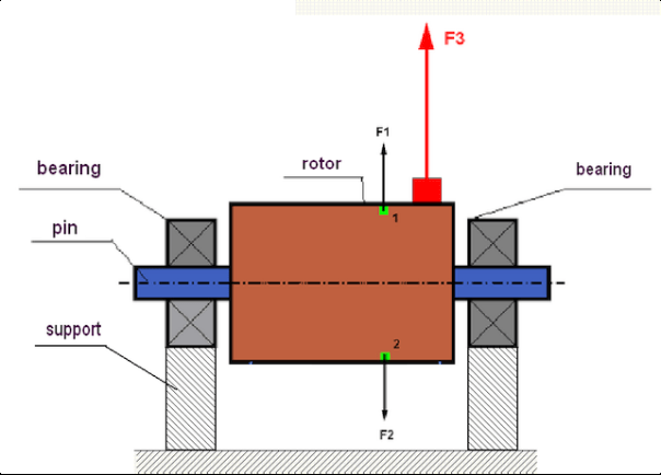
fig.1 Rotor and centrifugal forces.
In a perfectly balanced rotor, its mass is distributed symmetrically regarding the axis of the rotation. This means that any element of the rotor can correspond to another element located symmetrically in a relation to the axis of the rotation. During rotation, each rotor element acts upon by a centrifugal force directed in the radial direction (perpendicular to the axis of the rotor rotation). In a balanced rotor, the centrifugal force influencing any element of the rotor is balanced by the centrifugal force that influences the symmetrical element. For example, elements 1 and 2 (shown in fig.1 and colored in green) are influenced by centrifugal forces F1 and F2: equal in value and absolutely opposite in directions. This is true for all symmetrical elements of the rotor and thus the total centrifugal force influencing the rotor is equal to 0 the rotor is balanced. But if the symmetry of the rotor is broken (in Figure 1, the asymmetric element is marked in red), then the unbalanced centrifugal force F3 begins to act on the rotor.
Айналу кезінде бұл күш ротордың айналысымен бірге бағытын өзгертеді. Осы күштен туындайтын динамикалық жүктеме мойынтіректерге беріледі, бұл олардың жеделдетілген тозуына әкеледі. Сонымен қатар, осы айнымалы күштің әсерінен тіреуіштер мен ротор бекітілген іргетасқа циклдік деформация пайда болады, бұл вибрацияны туғызады. Ротордың дисбалансын және оған ілесетін вибрацияны жою үшін ротор симметриясын қалпына келтіретін теңестіру жүктерін орнату қажет.
Rotor balancing is an operation to eliminate imbalance by adding balancing masses.
The task of balancing is to find the value and places (angle) of the installation of one or more balancing masses.
Ротор типтері мен дисбаланс түрлері
Considering the strength of the rotor material and the magnitude of the centrifugal forces influencing it, the rotors can be divided into two types: rigid and flexible.
Rigid rotors at operating conditions under the influence of centrifugal force may get slightly deformed and the influence of this deformation in the calculations may therefore be neglected.
Deformation of flexible rotors on the other hand should never be neglected. The deformation of flexible rotors complicates the solution for the balancing problem and requires the use of some other mathematical models in comparison with the task of balancing rigid rotors. It is important to mention that the same rotor at low speeds of rotation can behave like rigid one and at high speeds it will behave like flexible one. Further on we will consider the balancing of rigid rotors only.
Дисбаланстанған массалардың ротор ұзындығы бойынша таралуына байланысты дисбаланстың екі түрін ажыратуға болады — статикалық және динамикалық. Бұл статикалық және динамикалық ротор балансировкасына да қатысты.
The static imbalance of the rotor occurs without the rotation of the rotor. In other words, it is quiescent when the rotor is under the influence of gravity and in addition it turns the “heavy point” down. An example of a rotor with the static imbalance is presented in Fig.2

Fig.2
The dynamic imbalance occurs only when the rotor spins.
An example of a rotor with the dynamic imbalance is presented in Fig.3.
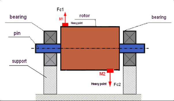
Fig.3. Dynamic imbalance of rotor – couple of the centrifugal forces
In this case, imbalanced equal masses M1 and M2 are located in different surfaces – in different places along the length of the rotor. In the static position, i.e. when the rotor does not spin, the rotor may only be influenced by gravity and the masses therefore will balance each other. In dynamics when the rotor is spinning, the masses M1 and M2 start to be influenced by centrifugal forces FЎ1 and FЎ2. These forces are equal in value and are opposite in the direction. However, since they are located in different places along the length of the shaft and are not on the same line, the forces do not compensate each other. The forces of FЎ1 and FЎ2 create a moment impacted to the rotor. That is why this imbalance has another name “momentary”. Accordingly, non-compensated centrifugal forces influence the bearing supports, which can significantly exceed the forces that we relied on and also reduce the service life for the bearings.
Since this type of imbalance occurs only in dynamics during the rotor spinning, thus it is called dynamic. It can not be eliminated in the static balancing (or so called “on the knives”) or in any other similar ways. To eliminate the dynamic imbalance, it is necessary to set two compensating weights that will create a moment equal in value and opposite in direction to the moment arising from the masses of M1 and M2. Compensating masses do not necessarily have to be installed opposite to the masses M1 and M2 and be equal to them in value. The most important thing is that they create a moment that fully compensates right at the moment of imbalance.
Жалпы жағдайда M1 және M2 массалары бір-біріне тең болмауы мүмкін, сондықтан статикалық және динамикалық дисбаланстың үйлесімі орын алады. Теориялық тұрғыдан дәлелденген: қатаң ротордың дисбалансын жою үшін ротор ұзындығы бойынша орналасқан екі жүкті орнату қажетті де, жеткілікті де. Бұл жүктер динамикалық дисбалансқа байланысты моментті де, масса симметриясының ротор осіне қатысты бұзылуынан туындайтын орталықтан тебетін күшті де (статикалық дисбаланс) өтейді. Әдетте динамикалық дисбаланс биліктер сияқты ұзын роторларға тән, ал статикалық дисбаланс — жіңішке роторларға тән. Алайда жіңішке ротор оське қатысты қисайып орнатылса немесе деформацияланса (атал мыс «дөңгелектің дірілі» деп аталатын жағдай), мұндай жағдайда дұрыс өтеуші момент жасайтын түзету жүктерін орнату қиын болатындықтан, динамикалық дисбалансты жою күрделенеді (4-суретті қараңыз).
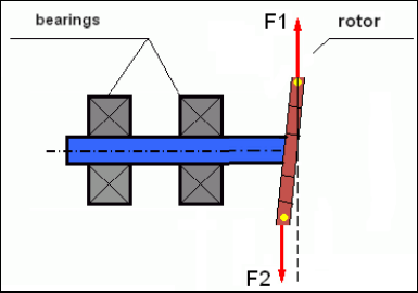
Fig.4 Dynamic balancing of the wobbling wheel
Since the narrow rotor shoulder creates a short moment, it may require correcting weights of a large mass. But at the same time there is an additional so-called “induced imbalance” associated with the deformation of the narrow rotor under the influence of centrifugal forces from the correcting masses.
See the example:
«Қатаң роторларды балансировкалаудың әдістемелік нұсқаулары» ISO 1940-1:2003 Mechanical vibration – Balance quality requirements for rotors in a constant (rigid) state – Part 1: Specification and verification of balance tolerances
This is visible for narrow fan wheels, which, in addition to the power imbalance, also influences an aerodynamic imbalance. And it is important to bear in mind that the aerodynamic imbalance, in fact the aerodynamic force, is directly proportional to the angular velocity of the rotor, and to compensate it, the centrifugal force of the correcting mass is used, which is proportional to the square of the angular velocity. Therefore, the balancing effect may only occur at a specific balancing frequency. At other speeds there would be an additional gap. The same can be said about electromagnetic forces in an electromagnetic motor, which are also proportional to the angular velocity. In other words it is impossible to eliminate all causes of vibration of the mechanism by any means of balancing.
Тербелістің негіздері
Vibration is a reaction of the mechanism design to the effect of cyclic excitation force. This force can may a different nature.
- Ротордың дисбалансынан туындайтын орталықтан тепкіш күш — «ауыр нүктеге» әсер ететін өтелмеген күш. Дәл осы күш, сондай-ақ одан туындайтын тербеліс ротор балансировкасы арқылы жойылады.
- Interacting forces, that have a “geometric” nature and arise out of errors in the manufacture and installation of mating parts. These forces can occur, for instance, due to the non-roundness of the shaft journal, errors in the tooth profiles in gears, the waviness of the bearing treadmills, misalignment of the mating shafts, etc. in case of non-roundness of the necks, the shaft axis will shift depending on the angle of rotation of the shaft. Although this vibration is manifested at the rotor speed, it is almost impossible to eliminate it with the balancing.
- Aerodynamic forces arising from the rotation of the impeller fans and other blade mechanisms. Hydrodynamic forces arising from the rotation of hydraulic pump impellers, turbines, etc.
- Электр машиналарының жұмысынан туындайтын электромагниттік күштер — мысалы, ротор орамаларының асимметриясы, қысқа тұйықталған оралымдардың болуы және т.б. себептерден пайда болады.
The magnitude of vibration (for example, its amplitude AB) depends not only on the magnitude of the excitation force Fт acting on the mechanism with the circular frequency ω, but also on the stiffness k of the structure of the mechanism, its mass m, and damping coefficient C.

Various types of sensors can be used to measure vibration and balance mechanisms, including:
- absolute vibration sensors designed to measure vibration acceleration (accelerometers) and vibration velocity sensors;
- тербелісті өлшеуге арналған салыстырмалы тербеліс сенсорлары — вихрлы токты немесе сыйымдылықты.
In some cases (when the structure of the mechanism allows it) sensors of force can also be used to examine its vibration weight.
Particularly, they are widely used to measure the vibration weight of the supports of hardbearing balancing machines.
Therefore vibration is the reaction of the mechanism to the influence of external forces. The amount of vibration depends not only on the magnitude of the force acting on the mechanism, but also on the rigidity of the mechanism. Two forces with the same magnitude can lead to different vibrations. In mechanisms with a rigid support structure, even with the small vibration, the bearing units can be significantly influenced by dynamic weights. Therefore, when balancing mechanisms with stiff legs apply the force sensors, and vibration (vibro accelerometers). Vibration sensors are only used on mechanisms with relatively pliable supports, right when the action of unbalanced centrifugal forces leads to a noticeable deformation of the supports and vibration. Force sensors are used in rigid supports even when significant forces arising from imbalance do not lead to significant vibration.
Құрылымның резонансы
We have previously mentioned that rotors are divided into rigid and flexible. The rigidity or flexibility of the rotor should not be confused with the stiffness or mobility of the supports (foundation) on which the rotor is located. The rotor is considered rigid when its deformation (bending) under the action of centrifugal forces can be neglected. The deformation of the flexible rotor is relatively large: it cannot be neglected.
Бұл мақалада тек қатаң роторларды балансировкалау қарастырылады. Қатаң (деформацияланбайтын) ротор, өз кезегінде, қатаң немесе иілгіш (серпімді) тіректерде орналасуы мүмкін. Тіректердің осы қаттылығы/иілгіштігі ротор айналу жиілігі мен пайда болатын орталықтан тепкіш күштердің шамасына байланысты салыстырмалы екені анық. Шартты шекара — ротор тіректері/фундаментінің еркін тербелісінің жиілігі. Механикалық жүйелер үшін еркін тербелістің пішіні мен жиілігі механикалық жүйе элементтерінің массасы мен серпімділігімен анықталады. Яғни, меншікті тербеліс жиілігі — механикалық жүйенің ішкі сипаттамасы болып табылады және сыртқы күштерге тәуелді емес. Тепе-теңдік күйінен ауытқыған тіректер серпімділік есебінен тепе-теңдік жағдайына оралуға тырысады. Алайда массивті ротордың инерциясына байланысты бұл процесс сөнетін тербеліс сипатына ие болады. Бұл тербелістер ротор-тірек жүйесінің меншікті тербелістері болып табылады. Олардың жиілігі ротор массасы мен тіректер серпімділігінің қатынасына байланысты.

When the rotor begins to rotate and the frequency of its rotation approaches the frequency of its own oscillations, the vibration amplitude increases sharply, which can even lead to the destruction of the structure.
There is a phenomenon of mechanical resonance. In the resonance region, a change in the speed of rotation by 100 rpm can lead to an increase in a vibration tenfold. In this case (in the resonance region) the vibration phase changes by 180°.
Механизм конструкциясы нашар жобаланған жағдайда және ротордың жұмыс жиілігі меншікті тербеліс жиілігіне жақын болса, механизмнің жұмысы рұқсат етілмейтін жоғары тербеліс деңгейіне байланысты мүмкін болмай қалады. Стандартты балансировка әдістері де қолданылмайды, өйткені айналу жиілігінің незначительды өзгеруі кезінде параметрлер күрт өзгереді. Бұл жағдайда резонанс аймағында балансировкалаудың арнайы әдістері қолданылады, бірақ олар осы мақалада толық баяндалмаған. Механизмнің меншікті тербеліс жиілігін сызып өту кезінде (ротор тоқтатылғанда) немесе соққы беру және жүйенің соққыға жауабын кейіннен спектрлік талдау арқылы анықтауға болады. «Balanset-1» осы әдістермен механикалық құрылымдардың меншікті жиіліктерін анықтау мүмкіндігін береді.
For mechanisms whose operating speed is higher than the resonance frequency, that is, operating in the resonant mode, supports are considered as mobile ones and vibration sensors are used to measure, mainly vibration accelerometers that measure the acceleration of structural elements. For mechanisms operating in hard bearing mode, supports are considered as rigid. In this case, force sensors are used.
Механикалық жүйенің сызықтық және сызықтық емес модельдері
Mathematical models (linear) are used for calculations when balancing rigid rotors. The linearity of the model means that one model is directly proportionally (linearly) dependent on the other. For example, if the uncompensated mass on the rotor is doubled, then the vibration value will be doubled correspondingly. For rigid rotors you can use a linear model because such rotors are not deformed. It is no longer possible to use a linear model for flexible rotors. For a flexible rotor, with an increase of the mass of a heavy point during rotation, an additional deformation will occur, and in addition to the mass, the radius of the heavy point will also increase. Therefore, for a flexible rotor, the vibration will more than double, and the usual calculation methods will not work. Also, a violation of the linearity of the model can lead to a change in the elasticity of the supports at their large deformations, for example, when small deformations of the supports work some structural elements, and when large in the work include other structural elements. Therefore it is impossible to balance the mechanisms that are not fixed at the base, and, for example, are simply established on a floor. With significant vibrations, the unbalance force can detach the mechanism from the floor, thereby significantly changing the stiffness characteristics of the system. The engine legs must be securely fastened, bolted fasteners tightened, the thickness of the washers must provide sufficient rigidity, etc. With broken bearings, a significant displacement of the shaft and its impacts is possible, which will also lead to a violation of linearity and the impossibility of carrying out high-quality balancing.
Methods and devices for balancing
As mentioned above, balancing is the process of combining the main Central axis of inertia with the axis of rotation of the rotor.
The specified process can be executed in two ways.
The first method involves the processing of the rotor axles, which is performed in such a way that the axis passing through the centers of the section of the axles with the main Central axis of inertia of the rotor. This technique is rarely used in practice and will not be discussed in detail in this article.
The second (most common) method involves moving, installing or removing corrective masses on the rotor, which are placed in such a way that the axis of inertia of the rotor is as close as possible to the axis of its rotation.
Moving, adding or removing corrective masses during balancing can be done using a variety of technological operations, including: drilling, milling, surfacing, welding, screwing or unscrewing screws, burning with a laser beam or electron beam, electrolysis, electromagnetic welding, etc.
The balancing process can be performed in two ways:
- балансировкаланған роторлардың жинақтауы (өздерінің мойынтіректерінде);
- балансировка машиналарында роторларды балансировкалау.
To balance the rotors in their own bearings we usually use specialized balancing devices (kits), which allows us to measure the vibration of the balanced rotor at the speed of its rotation in a vector form, i.e. to measure both the amplitude and phase of vibration.
Currently, these devices are manufactured on the basis of microprocessor technology and (in addition to the measurement and analysis of vibration) provide automated calculation of the parameters of corrective weights that must be installed on the rotor to compensate its imbalance.
These devices include:
- – measuring and computing unit, made on the basis of a computer or industrial controller;
- екі (немесе одан да көп) тербеліс сенсоры;
- фазалық бұрыш сенсоры;
- нысанда сенсорларды орнатуға арналған жабдық;
- бір, екі немесе одан да көп түзету жазықтығындағы ротор дисбалансы параметрлерін өлшеудің толық циклін орындауға арналған мамандандырылған бағдарламалық жасақтама.
For balancing rotors on balancing machines in addition to a specialized balancing device (measuring system of the machine) it is required to have an “unwinding mechanism” designed to install the rotor on the supports and ensure its rotation at a fixed speed.
Currently, the most common balancing machines exist in two types:
- резонанстан жоғары (иілгіш тіректермен);
- қатты тіректермен (қатаң тіректермен).
Over-resonant machines have a relatively pliable supports, made, for example, on the basis of the flat springs.
The natural oscillation frequency of these supports is usually 2-3 times lower than the speed of the balanced rotor, which is mounted on them.
Vibration sensors (accelerometers, vibration velocity sensors, etc.) are usually used to measure the vibration of the supports of a resonant machine.
In the hardbearing balancing machines are used relatively-rigid supports, natural oscillation frequencies of which should be 2-3 times higher than the speed of the balanced rotor.
Force sensors are usually used to measure the vibration weight on the supports of the machine.
The advantage of the hard bearing balancing machines is that they can be balanced at relatively low rotor speeds (up to 400-500 rpm), which greatly simplifies the design of the machine and its foundation, as well as increases the productivity and safety of balancing.
Balancing technique
Balancing eliminates only the vibration which is caused by the asymmetry of the rotor mass distribution relative to its axis of rotation. Other types of the vibration cannot be eliminated by the balancing!
Balancing is the subject to technically serviceable mechanisms, the design of which ensures the absence of resonances at the operating speed, securely fixed on the foundation, installed in serviceable bearings.
The faulty mechanism is the subject to a repair, and only then – to a balancing. Otherwise, qualitative balancing impossible.
Balancing cannot be a substitute for repair!
The main task of balancing is to find the mass and the place (angle) of installation of compensating weights, which are balanced by centrifugal forces.
As mentioned above, for rigid rotors it is generally necessary and sufficient to install two compensating weights. This will eliminate both the static and dynamic rotor imbalance. A general scheme of the vibration measurement during balancing looks like the following:
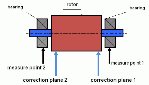
fig.5 Dynamic balancing – correction planes and measure points
Vibration sensors are installed on the bearing supports at points 1 and 2. The speed mark is fixed right on the rotor, a reflective tape is glued usually. The speed mark is used by the laser tachometer to determine the speed of the rotor and the phase of the vibration signal.
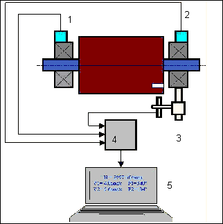
6-сурет. Balanset-1 пайдаланып екі жазықтықта балансировкалау кезінде сенсорларды орнату
1,2-vibration sensors, 3-phase, 4- USB measuring unit, 5-laptop
In most cases, dynamic balancing is carried out by the method of three starts. This method is based on the fact that test weights of an already-known mass are installed on the rotor in series in 1 and 2 planes; so the masses and the place of installation of balancing weights are calculated based on the results of changing the vibration parameters.
Салмақ орнатылатын орын түзету жазықтығы деп аталады. Әдетте, түзету жазықтықтары ротор орнатылған мойынтірек тіректері аймағында таңдалады.
Бастапқы тербеліс бірінші іске қосу кезінде өлшенеді. Содан кейін белгілі массасы бар сынақ салмағы ротордың тіректердің біріне жақын жеріне орнатылады. Екінші іске қосу жүргізіліп, сынақ салмағын орнатудың әсерінен өзгеруі тиіс тербеліс параметрлері өлшенеді. Содан кейін бірінші жазықтықтағы сынақ салмағы алынып, екінші жазықтыққа орнатылады. Үшінші іске қосу жүргізіліп, тербеліс параметрлері өлшенеді. Сынақ салмағы алынғаннан кейін бағдарлама балансировка салмақтарын орнатудың массасы мен орнын (бұрыштарын) автоматты түрде есептейді.
The point in setting up test weights is to determine how the system responds to the imbalance change. When we know the masses and the location of the sample weights, the program can calculate the so-called influence coefficients, showing how the introduction of a known imbalance affects the vibration parameters. The coefficients of influence are the characteristics of the mechanical system itself and depend on the stiffness of the supports and the mass (inertia) of the rotor-support system.
For the same type of mechanisms of the same design, the coefficients of influence will be similar. You can save them in your computer memory and use them afterwards for balancing the same type of mechanisms without carrying out test runs, which greatly improves the performance of the balancing. We should also note that the mass of test weights should be chosen as such so that the vibration parameters vary markedly when installing test weights. Otherwise, the error in calculating the coefficients of the affect increases and the quality of balancing deteriorates.
Balanset-1 құрылғысына арналған нұсқаулықта балансировкаланатын ротордың массасы мен айналу жиілігіне байланысты сынақ салмағының массасын шамамен анықтауға болатын формула келтірілген. 1-суреттен түсінуге болатындай, орталықтан тепкіш күш радиалды бағытта, яғни ротор осіне перпендикуляр бағытта әрекет етеді. Сондықтан тербеліс сенсорлары олардың сезімталдық осі де радиалды бағытта бағытталатындай етіп орнатылуы тиіс. Әдетте фундаменттің горизонталь бағыттағы қаттылығы аз болғандықтан, горизонталь бағыттағы тербеліс жоғарырақ болады. Сондықтан сенсорлардың сезімталдығын арттыру үшін олардың сезімталдық осі де горизонталь бағытта бағытталатындай етіп орнату керек. Дегенмен принципті айырмашылық жоқ. Радиалды бағыттағы тербелістен басқа, ротордың айналу осі бойынша осьтік бағыттағы тербелісті де бақылау қажет. Бұл тербеліс әдетте дисбалансқа емес, басқа себептерге, негізінен муфта арқылы жалғанған білдектердің центрден ауытқуы мен дұрыс орналаспауына байланысты туындайды. Бұл тербелісті балансировкамен жою мүмкін емес — бұл жағдайда центрлеу жұмыстары талап етіледі. Іс жүзінде мұндай механизмдерде ротор дисбалансы да, білдектердің центрден ауытқуы да бір мезгілде кездеседі, бұл тербелісті жою міндетін айтарлықтай қиындатады. Мұндай жағдайларда алдымен центрлеу, содан кейін механизмді балансировкалау керек. (Дегенмен айтарлықтай бұралу дисбалансы кезінде фундамент конструкциясының «бұрауынан» байланысты осьтік бағытта да тербеліс туындайды).
Өлшеу дәлдігі және қателерді талдау
Өлшеу дәлдігін түсіну кәсіби теңгеру жұмыстары үшін аса маңызды. Balanset-1A келесі өлшеу дәлдігін қамтамасыз етеді:
| Parameter | Дәлдік формуласы | Мысал (типтік мәндер үшін) |
|---|---|---|
| Діріл жылдамдығының СКМ мәні | ±(0.1 + 0.1×Vmeasured) mm/sec | 5 мм/сек үшін: ±0,6 мм/сек 10 мм/сек үшін: ±1,1 мм/сек |
| Айналу жиілігі | ±(1 + 0.005×Nmeasured) rpm | 1000 айн/мин үшін: ±6 айн/мин 3000 айн/мин үшін: ±16 айн/мин |
| Фаза өлшеуі | ±1° | Барлық айналу жылдамдықтарында тұрақты дәлдік |
⚠️ Дәл теңгеру үшін маңызды шарт
- !Сынақ салмағы амплитуданы >20-30%-ға өзгертуі тиіс and/or Фаза өзгерісі >20-30°
- !Өзгерістер кішірек болса, өлшеу қателері едәуір артады
- !Діріл амплитудасы мен фазасының тұрақтылығы өлшеулер арасында 10-15%-дан аспауы керек
- !Ауытқу 15%-дан асса, резонанс жағдайларын немесе механикалық ақауларды тексеріңіз
Теңгеру механизмдерінің сапасын бағалау өлшемдері
Quality of rotor (mechanisms) balancing can be estimated in two ways. The first method involves comparing the value of the residual imbalance determined during the balancing with the tolerance for the residual imbalance. The specified tolerances for various classes of rotors installed in the standard ISO 21940-11 «Mechanical vibration – Rotor balancing – Part 11: Procedures and tolerances for rotors with rigid behaviour» (formerly ISO 1940-1).
Алайда осы рұқсаттарды орындау механизмнің жұмыс сенімділігін толық кепілдей алмайды, өйткені минималды діріл деңгейіне жету механизмнің сенімділігімен тікелей байланысты. Бұл механизмдегі дірілдің ротордың қалдық балансталмаушылығымен байланысты күш шамасымен ғана анықталмайтынына, сондай-ақ механизмнің конструктивтік элементтерінің қаттылығы K, массасы M, сөндіру коэффициенті және айналу жылдамдығы сияқты басқа параметрлерге де тәуелді екеніне байланысты. Сондықтан механизмнің динамикалық сапасын (оның ішінде теңгеру сапасын) бағалау үшін кейбір жағдайларда бірқатар стандарттармен регламенттелген механизмнің қалдық діріл деңгейін бағалау ұсынылады.
The most common standard regulating permissible vibration levels of mechanisms is ISO 10816-3:2009 Preview Mechanical vibration — Evaluation of machine vibration by measurements on non-rotating parts — Part 3: Industrial machines with nominal power above 15 kW and nominal speeds between 120 r/min and 15 000 r/min when measured in situ.»
With its help, you can set the tolerance on all types of machines, taking into account the power of their electric drive.
In addition to this universal standard, there are a number of specialized standards developed for specific types of mechanisms. For example,
- ISO 14694:2003 "Өнеркәсіптік желдеткіштер – Теңгеру сапасы мен діріл деңгейлеріне қойылатын талаптар"
- ISO 7919-1-2002 “Vibration of machines without reciprocating motion. Measurements on rotating shafts and evaluation criteria. General guidance.»
🛡️ ЕО талаптарына сәйкестік үшін маңызды қауіпсіздік ескертпелері
- !Тәуекелді бағалау қажет: Теңгеру жұмыстарын бастамас бұрын EN ISO 12100 бойынша тәуекелді бағалауды орындаңыз
- !Білікті персонал: Теңгеру жұмыстарын тек оқытылған және сертификатталған персонал жүргізуге тиіс
- !Жеке қорғаныс құралдары: EN 166 (көзді қорғау) және EN 352 (есту органдарын қорғау) стандарттарына сәйкес тиісті жеке қорғаныш құралдарын міндетті түрде пайдаланыңыз
- !Төтенше жағдай рәсімдері: Авариялық тоқтату рәсімдерін нақты белгілеңіз және барлық операторлардың олармен таныс болуын қамтамасыз етіңіз
- !Documentation: Бақылаушылық пен нормативтік сәйкестікті қамтамасыз ету үшін барлық теңгеру операцияларының егжей-тегжейлі жазбаларын жүргізіңіз
ЕО сәйкестігі және қауіпсіздік ақпараты
Сәйкестік декларациясы
Balanset-1A портативті балансировкалау құрылғысы мынадай Еуропалық Одақ директивалары мен стандарттарына сәйкес келеді:
| ЕО директивасы/стандарты | Сәйкестік мәліметтері | Қауіпсіздік талаптары |
|---|---|---|
| Машиналарға қатысты 2006/42/EC директивасы | Машиналар мен қауіпсіздік компоненттеріне қойылатын қауіпсіздік талаптары | Тәуекелді бағалау, қауіпсіздік нұсқаулықтары, CE маркировкасы |
| Электромагниттік үйлесімділік туралы 2014/30/EU директивасы | Электромагниттік үйлесімділікке қойылатын талаптар | Электромагниттік кедергілерге иммунитет |
| RoHS директивасы 2011/65/EU | Қауіпті заттарды шектеу | Қорғасынсыз, сынапсыз, кадмийсіз компоненттер |
| WEEE директивасы 2012/19/EU | Электрлік және электрондық жабдықтардың қалдықтары | Дұрыс жою және қайта өңдеу рәсімдері |
| EN ISO 12100:2010 | Машиналардың қауіпсіздігі — Жобалаудың жалпы принциптері | Тәуекелді бағалау және тәуекелді азайту |
| EN 60825-1:2014 | Лазерлік өнімдердің қауіпсіздігі — 1-бөлім | 2-сыныпты лазер қауіпсіздігіне қойылатын талаптар |
| EN ISO 14120:2015 | Қорғаныс қалқандары — Жалпы талаптар | Айналмалы машина механизмдерінің қауіп-қатерінен қорғау |
Электрлік қауіпсіздік стандарттары
- ✓EN 61010-1: Өлшеу, басқару және зертханалық мақсаттарда қолданылатын электрлік жабдықтарға қойылатын қауіпсіздік талаптары
- ✓EN 60950-1: Ақпараттық технологиялар жабдықтарының қауіпсіздігі (USB арқылы қуатталатын құрылғы)
- ✓IEC 61000 сериясы: Электромагниттік үйлесімділік стандарттары
- ✓Жұмыс кернеуі: 5В тұрақты ток USB арқылы (өте төмен кернеу)
- ✓Қуат тұтынуы: < 2.5W
- ✓Қорғаныс класы: IP54 (dust-protected; splash-water resistant)
Айналмалы жабдықпен жұмыс қауіпсіздігі
⚠️ Міндетті қауіпсіздік рәсімдері (EN ISO 12100)
WARNING: Айналмалы механизмдермен жұмыс кезінде мынадай қауіпсіздік талаптарын сақтаңыз:
- !EN ISO 14118: Кенеттен іске қосылудың алдын алу — датчикті орнатудан бұрын ажырату/белгілеу рәсімдерін (lockout/tagout) қолданыңыз
- !EN ISO 14120: Барлық айналмалы жабдықтың қорғаныш қаптамасының дұрыс орнатылғанына көз жеткізіңіз
- !EN ISO 13857: Айналмалы бөліктерден қауіпсіз ең аз қашықтықты сақтаңыз (дене үшін 500 мм, саусақтар үшін 120 мм)
- !Жеке қорғаныс құралдары: EN 166 талаптарына сай қорғаныш көзілдірік, EN 352 бойынша есту қорғанышын киіңіз және ілмелі киімнен аулақ болыңыз
- !Айналмалы механизмдер қозғалыста болған кезде датчиктерді немесе сынақ салмақтарын ешқашан орнатпаңыз
- !Датчикті орнатпас бұрын машинаның толық тоқтағанына және бекітілгеніне көз жеткізіңіз
- !Төтенше тоқтату: Оператор орнынан 3 метр аралығында қолжетімді болуы тиіс
- !Теңгеру жұмыстарын тек біліктілігі расталған және сертификатталған мамандар ғана орындауы тиіс
Лазерлік қауіпсіздік класификациясы
🔴 2-сынып лазерлік құрылғы (EN 60825-1:2014)
- Wavelength: 650 нм (қызыл көрінетін жарық)
- Максималды шығыс қуаты: < 1 mW
- Beam diameter: 100 мм қашықтықта 3–5 мм
- Divergence: < 1.5 mrad
- Қауіпсіздік класификациясы: Қысқа мерзімді әсерде көзге қауіпсіз (< 0.25 sec)
- Міндетті таңбалау: "ЛАЗЕРЛІК СӘУЛЕ — ШОҚҚА ҚАРАМАҢЫЗ — 2-КЛАСС ЛАЗЕРЛІК ӨНІМ"
- Access class: Шектеусіз (жалпы қол жеткізуге рұқсат берілген)
Лазерлік қауіпсіздік рәсімдері:
- Лазер шоғына әдейі қарамаңыз
- Лазерді адамдарға, көлік құралдарына немесе ұшақтарға бағыттамаңыз
- Лазер шоғын оптикалық аспаптармен (телескоп, дүрбі) бақыламаңыз
- Жылтыр беттерден болатын зеркалды шағылысулардан сақ болыңыз
- Пайдаланбаған кезде лазерді өшіріңіз
- Көзге сәуле тиген жағдайларды дереу хабарлаңыз
- Ұзақ уақыт жұмыс кезінде лазерлік қорғаныш көзілдірігін қолданыңыз (650 нм толқын ұзындығында OD 2+)
Өлшеу дәлдігі және калибрлеу
| Parameter | Accuracy | Калибрлеу жиілігі |
|---|---|---|
| Вибрациялық амплитуда | ±5% of reading | Жылына бір рет немесе 1000 сағат сайын |
| Фаза өлшеу | ±1° | Annually |
| Rotation speed | ±0.1% of reading | Annually |
| Сенсор сезімталдығы | 13 mV/(mm/s) ±10% | Сенсорларды ауыстырған кезде |
Қоршаған ортаға қойылатын талаптарға сәйкестік
- ✓Жұмыс ортасы: 5°C to 50°C, < 85% RH конденсацияланбайтын
- ✓Сақтау ортасы: -20°C to 70°C, < 95% RH конденсацияланбайтын
- ✓Altitude: Теңіз деңгейінен 2000 м биіктікке дейін
- ✓Діріл төзімділігі: IEC 60068-2-6 (10–500 Гц, 2g үдеу)
- ✓Соққыға төзімділік: IEC 60068-2-27 (15g, 11 мс ұзақтық)
- ✓IP rating: IP54 (dust-protected; splash-water resistant)
Пайдалану талаптары
- ✓Операторлар ЕО стандарттарына сәйкес машина қауіпсіздігі бойынша оқытудан өтуі тиіс
- ✓Пайдалануға дейін EN ISO 12100 бойынша тәуекелді бағалау жүргізілуі міндетті
- ✓Жабдықты өндірушінің техникалық шарттарына сәйкес күтіп ұстаңыз
- ✓Кез келген қауіпсіздік оқиғасы немесе жабдық ақаулығы туралы дереу хабарлаңыз
- ✓Балансировка операцияларының барлығы бойынша толық жазбаларды кейінгі тексерімділік үшін жүргізіп отырыңыз
Құжаттама талаптары
ЕО нормативтік талаптарын орындау үшін мынадай құжаттарды сақтаңыз:
- ✓EN ISO 12100 бойынша тәуекелді бағалау құжаттамасы
- ✓Операторларды оқыту жазбалары мен сертификаттар
- ✓Жабдықты калибрлеу және техникалық қызмет көрсету журналдары
- ✓Балансировка операцияларының күні, операторы және нәтижесі көрсетілген жазбалары
- ✓Қауіпсіздік оқиғалары туралы есептер және түзету шаралары
- ✓Жабдықты өзгерту немесе жөндеу бойынша құжаттама
Техникалық қолдау және қызмет көрсету
Техникалық қолдау, калибрлеу қызметтері және қосалқы бөлшектер үшін:
- ✓Manufacturer: Вибромералар
- ✓Location: Нарва, Эстония (ЕО)
- ✓Website: https://vibromera.eu
- ✓Қолдау тілдері: Барлық негізгі тілдер. Мәтін арқылы байланыс мүмкіндігі бар.
- ✓Қызмет көрсету аймағы: Бүкіл әлем бойынша жеткізу қолжетімді
- ✓Warranty: Сатып алынған күннен бастап 12 ай
- ✓Калибрлеу қызметі: Уәкілетті қызмет орталықтары арқылы қолжетімді

