ਬੈਲੇਂਸਿੰਗ ਸੇਵਾਵਾਂ › ਟਰਬਾਈਨਾਂ & ਟਰਬੋਚਾਰਜਰ
ਟਰਬਾਈਨ & ਟਰਬੋਚਾਰਜਰ ਬੈਲੇਂਸਿੰਗ — ਥਾਂ 'ਤੇ ਹੀ, ਓਪਰੇਟਿੰਗ ਸਪੀਡ 'ਤੇ
ਭਾਫ਼ ਟਰਬਾਈਨਾਂ, ਗੈਸ ਟਰਬਾਈਨਾਂ, ਹਾਈਡਰੋ ਰਨਰ, ਵਿੰਡ-ਟਰਬਾਈਨ ਦੇ ਮੁੱਖ ਸ਼ਾਫਟ ਅਤੇ ਉਦਯੋਗਿਕ ਟਰਬੋਚਾਰਜਰ ਰੋਟਰ ਇੰਨੀ ਤੇਜ਼ੀ ਨਾਲ ਘੁੰਮਦੇ ਹਨ ਕਿ ਮਾਈਕ੍ਰੋ-ਗ੍ਰਾਮ ਵਿਕੇਂਦਰਤਾ ਵੀ ਵਿਨਾਸ਼ਕਾਰੀ ਵਾਈਬ੍ਰੇਸ਼ਨ ਪੈਦਾ ਕਰ ਦਿੰਦੀ ਹੈ। ਅਸੀਂ ਉਹਨਾਂ ਨੂੰ ਸੰਤੁਲਿਤ ਕਰਦੇ ਹਾਂ ਇਨ੍ਹਾਂ ਦੇ ਆਪਣੇ ਬੇਅਰਿੰਗਾਂ ਵਿੱਚ, ਚੱਲਣ ਦੀ ਸਪੀਡ 'ਤੇ — ਨਾ ਕੋਈ ਖੋਲ੍ਹਣਾ, ਨਾ ਹੀ ਵਰਕਸ਼ਾਪ ਨੂੰ ਭੇਜਣਾ — ਅਤੇ ਨਤੀਜੇ ਨੂੰ ISO 20816 ਅਤੇ ISO 21940-11 ਦੇ ਵਿਰੁੱਧ ਦਸਤਾਵੇਜ਼ਬੱਧ ਕਰਦੇ ਹਾਂ।
ਸੰਖੇਪ ਵਿੱਚ: ਟਰਬਾਈਨ ਅਤੇ ਉਦਯੋਗਿਕ ਟਰਬੋਚਾਰਜਰ ਰੋਟਰਾਂ ਨੂੰ ਸੰਤੁਲਿਤ ਕੀਤਾ ਜਾਂਦਾ ਹੈ ਥਾਂ 'ਤੇ ਹੀ ਓਪਰੇਟਿੰਗ ਸਪੀਡ 'ਤੇ ਇਨਫਲੂਐਂਸ-ਕੋਐਫੀਸ਼ੀਐਂਟ ਵਿਧੀ ਦੀ ਵਰਤੋਂ ਕਰਦੇ ਹੋਏ। ਬੇਅਰਿੰਗ ਹਾਊਸਿੰਗਾਂ 'ਤੇ ਲੱਗੇ ਵਾਈਬ੍ਰੇਸ਼ਨ ਸੈਂਸਰ ਅਤੇ ਇੱਕ ਲੇਜ਼ਰ ਟੈਕੋਮੀਟਰ ਐਂਪਲੀਟਿਊਡ ਅਤੇ ਫੇਜ਼ ਮਾਪਦੇ ਹਨ; Balanset-1A ਇੱਕ ਜਾਂ ਦੋ ਪਲੇਨਾਂ ਲਈ ਸਹੀ ਸੁਧਾਰ ਮਾਸ ਅਤੇ ਐਂਗਲ ਦੀ ਗਣਨਾ ਕਰਦਾ ਹੈ; ਵਜ਼ਨ ਲਗਾਉਣ ਤੋਂ ਬਾਅਦ ਬਾਕੀ ਬਚੀ ਵਾਈਬ੍ਰੇਸ਼ਨ ਦੀ ਪੁਸ਼ਟੀ ਖਾਸ ਟਰਬਾਈਨ ਕਲਾਸ ਲਈ ISO 20816 ਜ਼ੋਨ ਸੀਮਾਵਾਂ ਅਤੇ ਰੋਟਰ ਲਈ ISO 21940-11 G-ਗ੍ਰੇਡ ਦੇ ਵਿਰੁੱਧ ਕੀਤੀ ਜਾਂਦੀ ਹੈ। ਪੂਰੀ ਪ੍ਰਕਿਰਿਆ — ਪਹਿਲੀ ਚਾਲ ਤੋਂ ਲੈ ਕੇ ਦਸਤਾਵੇਜ਼ੀ ਨਤੀਜੇ ਤੱਕ — ਆਮ ਤੌਰ 'ਤੇ ਸਾਈਟ 'ਤੇ ਇੱਕ ਕੰਮ-ਸ਼ਿਫਟ ਤੋਂ ਘੱਟ ਲੈਂਦੀ ਹੈ।
ਤੁਹਾਡੀ ਟਰਬਾਈਨ ਜਾਂ ਟਰਬੋਚਾਰਜਰ ਦੇ ਅਸੰਤੁਲਿਤ ਹੋਣ ਦੇ ਲੱਛਣ
ਹਾਈ-ਸਪੀਡ ਟਰਬਾਈਨ ਰੋਟਰ ਅਸੰਤੁਲਨ ਦੇ ਨਤੀਜਿਆਂ ਨੂੰ ਬਹੁਤ ਵਧਾ ਦਿੰਦੇ ਹਨ। ਇਨ੍ਹਾਂ ਚੇਤਾਵਨੀ ਸੰਕੇਤਾਂ ਨੂੰ ਕਦੇ ਵੀ ਨਜ਼ਰਅੰਦਾਜ਼ ਨਹੀਂ ਕਰਨਾ ਚਾਹੀਦਾ:
ਟਰਬਾਈਨਾਂ ਸੰਤੁਲਨ ਕਿਉਂ ਗੁਆਉਂਦੀਆਂ ਹਨ — ਅਤੇ ਇਸਦੀ ਕੀਮਤ ਕੀ ਹੈ
ਟਰਬਾਈਨ ਰੋਟਰ ਉਨ੍ਹਾਂ ਸਪੀਡਾਂ 'ਤੇ ਚੱਲਦੇ ਹਨ ਜਿੱਥੇ ਉਹ ਸਖ਼ਤ ਮਾਸ ਦੀ ਬਜਾਏ ਲਚਕਦਾਰ ਬਾਡੀਆਂ ਵਾਂਗ ਵਿਵਹਾਰ ਕਰਦੇ ਹਨ — ਇਹ ਆਪਣੇ ਹੀ ਭਾਰ ਹੇਠ ਅਤੇ ਏਅਰੋਡਾਇਨਾਮਿਕ ਲੋਡ ਹੇਠ ਥੋੜ੍ਹਾ ਝੁਕ ਜਾਂਦੇ ਹਨ, ਜਿਸ ਨਾਲ ਪ੍ਰਭਾਵੀ ਮਾਸ ਕੇਂਦਰ ਮੋਡਾਂ ਵਿਚਕਾਰ ਬਦਲਦਾ ਹੈ। ਅਸੰਤੁਲਨ ਇਸ ਰਾਹੀਂ ਇਕੱਠਾ ਹੁੰਦਾ ਹੈ ਬਲੇਡ ਦਾ ਖੋਰਾ ਅਤੇ ਜਮ੍ਹਾਂ ਹੋਣਾ ਸਟੀਮ ਅਤੇ ਗੈਸ ਟਰਬਾਈਨਾਂ ਵਿੱਚ, ਕੈਵੀਟੇਸ਼ਨ ਨੁਕਸਾਨ ਹਾਈਡਰੌਲਿਕ ਰਨਰਾਂ ਵਿੱਚ, ਬਰਫ਼ ਜੰਮਣਾ ਵਿੰਡ-ਟਰਬਾਈਨ ਬਲੇਡਾਂ 'ਤੇ, ਅਤੇ ਸੀਲ ਦਾ ਘਸਣਾ ਜੋ ਘੁੰਮ ਰਹੇ ਮਾਸ ਨੂੰ ਬਦਲਦਾ ਹੈ। ਟਰਬੋਚਾਰਜਰਾਂ ਵਿੱਚ, ਟਰਬਾਈਨ ਵ੍ਹੀਲ 'ਤੇ ਕਾਰਬਨ ਅਤੇ ਸੂਟ ਦੇ ਜਮ੍ਹਾਂ ਹੋਣਾ ਪ੍ਰਮੁੱਖ ਕਾਰਨ ਹੈ ਅਤੇ ਇਹ ਕੁਝ ਹਜ਼ਾਰ ਓਪਰੇਟਿੰਗ ਘੰਟਿਆਂ ਵਿੱਚ ਹੀ ਵਿਕਸਤ ਹੋ ਸਕਦਾ ਹੈ।
ਨਜ਼ਰਅੰਦਾਜ਼ ਕੀਤੇ ਟਰਬਾਈਨ ਅਸੰਤੁਲਨ ਦੀ ਕੀਮਤ ਬੇਅਰਿੰਗ ਬਦਲਣ ਤੋਂ ਕਿਤੇ ਵੱਧ ਹੁੰਦੀ ਹੈ: ਬਲੇਡ ਥਕਾਵਟ ਅਸਫਲਤਾਵਾਂ ਲੰਬੇ ਓਵਰਹਾਲ ਕਰਵਾਉਂਦੀਆਂ ਹਨ, ਸੀਲ ਰਗੜ ਲਈ ਸਟੀਕ ਦੁਬਾਰਾ-ਮਸ਼ੀਨਿੰਗ ਦੀ ਲੋੜ ਹੁੰਦੀ ਹੈ, ਅਤੇ ਇੱਕ ਬੇਸ-ਲੋਡ ਪਾਵਰ ਪਲਾਂਟ 'ਤੇ ਇੱਕ ਹੀ ਮਜਬੂਰੀ ਬੰਦੀ ਦੀ ਕੀਮਤ ਪੂਰੇ ਸਾਲਾਨਾ ਮੇਨਟੇਨੈਂਸ ਬਜਟ ਦੇ ਕਈ ਗੁਣਾ ਹੁੰਦੀ ਹੈ। ISO 20816 ਪਰਿਵਾਰ ਦੇ ਵਿਰੁੱਧ ਫੀਲਡ ਵਾਈਬ੍ਰੇਸ਼ਨ ਮਾਪ ਓਪਰੇਟਰਾਂ ਨੂੰ ਤੁਰੰਤ ਦਖਲ ਅਤੇ ਨਿਰੰਤਰ ਨਿਗਰਾਨੀ ਹੇਠ ਸੰਚਾਲਨ ਵਿਚਕਾਰ ਫੈਸਲਾ ਲੈਣ ਲਈ ਲੋੜੀਂਦਾ ਬਾਹਰਮੁਖੀ ਡਾਟਾ ਦਿੰਦਾ ਹੈ — ਇੱਕ ਯੋਜਨਾਬੱਧ ਸੁਧਾਰ ਅਤੇ ਇੱਕ ਅਯੋਜਿਤ ਬੰਦੀ ਵਿਚਕਾਰ ਫਰਕ।
ਵਾਈਬ੍ਰੇਸ਼ਨ ਅੱਧੀ ਕਰਨ ਨਾਲ ਬੇਅਰਿੰਗ ਦੀ ਉਮਰ ਕਈ ਗੁਣਾ ਕਿਉਂ ਵਧਦੀ ਹੈ
ਅਸੀਂ ਟਰਬਾਈਨ ਜਾਂ ਟਰਬੋਚਾਰਜਰ ਨੂੰ ਕਿਵੇਂ ਬੈਲੇਂਸ ਕਰਦੇ ਹਾਂ — ਕਦਮ ਦਰ ਕਦਮ
Balanset-1A ਨਾਲ ਫੀਲਡ ਬੈਲੇਂਸਿੰਗ ਇਨਫਲੂਐਂਸ-ਕੋਐਫੀਸ਼ੀਐਂਟ ਵਿਧੀ ਦੀ ਪਾਲਣਾ ਕਰਦੀ ਹੈ — ਉਹੀ ਪ੍ਰਕਿਰਿਆ ਜੋ ਤੁਸੀਂ ਖੁਦ ਡਿਵਾਈਸ ਨਾਲ ਚਲਾ ਸਕਦੇ ਹੋ। ਟਰਬਾਈਨਾਂ ਲਈ ਸ਼ੁੱਧਤਾ ਦੀਆਂ ਲੋੜਾਂ ਸਖ਼ਤ ਹਨ ਅਤੇ ਸੁਰੱਖਿਆ ਪ੍ਰੋਟੋਕੋਲ ਜ਼ਿਆਦਾਤਰ ਹੋਰ ਰੋਟਰਾਂ ਨਾਲੋਂ ਵੱਧ ਮੰਗ ਕਰਦੇ ਹਨ:
- ਬੇਸਲਾਈਨ ਮਾਪ ਲਓ। ਵਾਈਬ੍ਰੇਸ਼ਨ ਸੈਂਸਰ ਬੇਅਰਿੰਗ ਹਾਊਸਿੰਗਾਂ ਜਾਂ ਪੈਡਸਟਲਾਂ 'ਤੇ ਲਗਾਏ ਜਾਂਦੇ ਹਨ; ਇੱਕ ਲੇਜ਼ਰ ਟੈਕੋਮੀਟਰ ਸ਼ਾਫਟ ਫੇਜ਼ ਐਂਗਲ ਨੂੰ ਕੈਪਚਰ ਕਰਦਾ ਹੈ। ਇੱਕ ਸਥਿਰ-ਸਪੀਡ ਰਨ ਹਰੇਕ ਮਾਪ ਪਲੇਨ ਲਈ ਵਾਈਬ੍ਰੇਸ਼ਨ ਐਂਪਲੀਟਿਊਡ ਅਤੇ ਫੇਜ਼ ਰਿਕਾਰਡ ਕਰਦਾ ਹੈ ਅਤੇ ISO 20816 ਜ਼ੋਨ ਸਥਿਤੀ ਸਥਾਪਿਤ ਕਰਦਾ ਹੈ।
- ਟ੍ਰਾਇਲ ਵੇਟ ਲਗਾਓ। ਇੱਕ ਸ਼ੁੱਧਤਾ-ਮਸ਼ੀਨਡ ਟ੍ਰਾਇਲ ਵਜ਼ਨ ਬੈਲੇਂਸਿੰਗ ਪਲੇਨ 'ਤੇ ਇੱਕ ਜਾਣੀ-ਪਛਾਣੀ ਰੇਡੀਅਲ ਸਥਿਤੀ 'ਤੇ ਲਗਾਇਆ ਜਾਂਦਾ ਹੈ — ਆਮ ਤੌਰ 'ਤੇ ਇੱਕ ਬੋਲਟ-ਸਰਕਲ ਗਰੂਵ ਜਾਂ ਬਲੇਡ-ਟਿਪ ਪਾਕੇਟ। ਰੋਟਰ ਉਸੇ ਸਪੀਡ 'ਤੇ ਦੁਬਾਰਾ ਚੱਲਦਾ ਹੈ ਤਾਂ ਜੋ ਇੰਸਟਰੂਮੈਂਟ ਸਿਸਟਮ ਦੇ ਜਵਾਬ ਨੂੰ ਕੈਪਚਰ ਕਰ ਸਕੇ।
- ਉਪਕਰਨ ਨੂੰ ਗਣਨਾ ਕਰਨ ਦਿਓ। Balanset-1A ਹਰੇਕ ਪਲੇਨ ਲਈ ਸਹੀ ਸੁਧਾਰ ਮਾਸ ਅਤੇ ਐਂਗੁਲਰ ਸਥਿਤੀ ਨਿਰਧਾਰਤ ਕਰਨ ਲਈ ਇਨਫਲੂਐਂਸ-ਕੋਐਫੀਸ਼ੀਐਂਟ ਮੈਟ੍ਰਿਕਸ ਲਾਗੂ ਕਰਦਾ ਹੈ, ਜੋ ਰੋਟਰ ਜਿਓਮੈਟਰੀ ਦੁਆਰਾ ਆਗਿਆ ਪ੍ਰਾਪਤ ਸਭ ਤੋਂ ਸਖ਼ਤ ISO 21940-11 G-ਗ੍ਰੇਡ ਨੂੰ ਨਿਸ਼ਾਨਾ ਬਣਾਉਂਦਾ ਹੈ।
- ਕਰੈਕਸ਼ਨ ਵੇਟਾਂ ਫਿੱਟ ਕਰੋ। ਸੁਧਾਰ ਮਾਸ ਗਣਨਾ ਕੀਤੀ ਗਈ ਸਥਿਤੀ 'ਤੇ ਲਗਾਏ ਜਾਂਦੇ ਹਨ ਅਤੇ ਟ੍ਰਾਇਲ ਵਜ਼ਨ ਹਟਾ ਦਿੱਤਾ ਜਾਂਦਾ ਹੈ। OEM ਦਸਤਾਵੇਜ਼ੀਕਰਨ ਅਤੇ ਟ੍ਰੇਸੇਬਿਲਟੀ ਲਈ ਸ਼ੁੱਧ ਮਾਸ ਤਬਦੀਲੀ ਰਿਕਾਰਡ ਕੀਤੀ ਜਾਂਦੀ ਹੈ।
- ISO 20816 ਦੇ ਵਿਰੁੱਧ ਪੁਸ਼ਟੀ ਕਰੋ। ਓਪਰੇਟਿੰਗ ਸਪੀਡ 'ਤੇ ਇੱਕ ਅੰਤਿਮ ਰਨ ਪੁਸ਼ਟੀ ਕਰਦਾ ਹੈ ਕਿ ਬ੍ਰੌਡਬੈਂਡ RMS ਅਤੇ 1× ਸਿੰਕ੍ਰੋਨਸ ਐਂਪਲੀਟਿਊਡ ਲਾਗੂ ISO 20816 ਸਵੀਕ੍ਰਿਤੀ ਜ਼ੋਨ ਦੇ ਅੰਦਰ ਹਨ। ਨਤੀਜੇ ਜੌਬ ਰਿਪੋਰਟ ਵਿੱਚ ਸੇਵ ਕੀਤੇ ਜਾਂਦੇ ਹਨ।
ਅਸੀਂ ਕੀ ਬੈਲੇਂਸ ਕਰਦੇ ਹਾਂ
- ਉਦਯੋਗਿਕ ਸਟੀਮ-ਟਰਬਾਈਨ ਰੋਟਰ (ਬੈਕ-ਪ੍ਰੈਸ਼ਰ ਅਤੇ ਕੰਡੈਂਸਿੰਗ)
- ਗੈਸ-ਟਰਬਾਈਨ ਪਾਵਰ ਸੈਕਸ਼ਨ ਅਤੇ ਕੰਪਰੈਸਰ ਵ੍ਹੀਲ
- ਹਾਈਡ੍ਰੋਇਲੈਕਟ੍ਰਿਕ ਫ੍ਰਾਂਸਿਸ, ਕਾਪਲਾਨ ਅਤੇ ਪੈਲਟਨ ਰਨਰ
- ਵਿੰਡ-ਟਰਬਾਈਨ ਮੇਨ-ਸ਼ਾਫਟ ਅਸੈਂਬਲੀਆਂ
- ਉਦਯੋਗਿਕ ਟਰਬੋਚਾਰਜਰ ਟਰਬਾਈਨ ਅਤੇ ਕੰਪ੍ਰੈਸਰ ਵ੍ਹੀਲ (ਚੱਲਣ ਦੀ ਰਫ਼ਤਾਰ ≈60 000 RPM ਤੱਕ)
- ਮਾਈਕ੍ਰੋ-ਟਰਬਾਈਨ ਅਤੇ ORC ਐਕਸਪੈਂਡਰ ਰੋਟਰ
- ਟਰਬੋ-ਬਲੋਅਰ ਅਤੇ ਹਾਈ-ਸਪੀਡ ਕੰਪਰੈਸਰ ਇੰਪੈਲਰ
- ਐਕਸੀਅਲ ਅਤੇ ਰੇਡੀਅਲ ਟਰਬਾਈਨ ਟੈਸਟ-ਰਿਗ ਰੋਟਰ
ਸਹਿਣਸ਼ੀਲਤਾਵਾਂ & ਮਿਆਰ — ISO 20816 ਪਰਿਵਾਰ
ISO 20816 ਗੈਰ-ਘੁੰਮਣ ਵਾਲੇ ਹਿੱਸਿਆਂ (ਬੇਅਰਿੰਗ ਹਾਊਸਿੰਗ, ਪੈਡਸਟਲ) 'ਤੇ ਮਾਪਾਂ ਦੀ ਮਕੈਨੀਕਲ ਵਾਈਬ੍ਰੇਸ਼ਨ ਦਾ ਮੁਲਾਂਕਣ ਕਰਨ ਲਈ ਨਿਸ਼ਚਿਤ ਬਹੁ-ਭਾਗੀ ਮਿਆਰ ਹੈ। ਹਰੇਕ ਭਾਗ ਇੱਕ ਖਾਸ ਟਰਬਾਈਨ ਸ਼੍ਰੇਣੀ ਨੂੰ ਕਵਰ ਕਰਦਾ ਹੈ ਅਤੇ ਬ੍ਰੌਡਬੈਂਡ RMS ਵੇਗ ਜਾਂ ਵਿਸਥਾਪਨ ਲਈ ਚਾਰ ਗੰਭੀਰਤਾ ਜ਼ੋਨ (A–D) ਪਰਿਭਾਸ਼ਿਤ ਕਰਦਾ ਹੈ:
- ISO 20816-2 — 50 MW ਤੋਂ ਵੱਧ ਦੇ ਭੂਮੀ-ਅਧਾਰਿਤ ਸਟੀਮ ਟਰਬਾਈਨ ਅਤੇ ਜਨਰੇਟਰ। ਜ਼ੋਨ A/B ਦੀਆਂ ਸੀਮਾਵਾਂ ਆਮ ਤੌਰ 'ਤੇ 2.3 ਅਤੇ 4.5 mm/s RMS ਹੁੰਦੀਆਂ ਹਨ; ਜ਼ੋਨ D (ਟ੍ਰਿਪ) ਆਮ ਤੌਰ 'ਤੇ 7.1 mm/s ਹੁੰਦਾ ਹੈ।
- ISO 20816-4 — 3 MW ਤੋਂ ਵੱਧ ਪਾਵਰ ਆਉਟਪੁੱਟ ਵਾਲੇ ਗੈਸ ਟਰਬਾਈਨ, ਜਿਸ ਵਿੱਚ ਉਦਯੋਗਿਕ ਏਅਰੋਡੈਰੀਵੇਟਿਵ ਯੂਨਿਟ ਸ਼ਾਮਲ ਹਨ। ਬੇਅਰਿੰਗ-ਹਾਊਸਿੰਗ ਵਾਈਬ੍ਰੇਸ਼ਨ ਅਤੇ ਸ਼ਾਫਟ-ਸਾਪੇਖ ਵਿਸਥਾਪਨ ਲਈ ਵੱਖ-ਵੱਖ ਸੀਮਾਵਾਂ ਨਿਰਧਾਰਿਤ ਕਰਦਾ ਹੈ।
- ISO 20816-5 — ਬਿਜਲੀ ਘਰਾਂ ਵਿੱਚ ਹਾਈਡ੍ਰੌਲਿਕ ਮਸ਼ੀਨਾਂ (ਪੰਪ ਅਤੇ ਟਰਬਾਈਨ), ਜਿਸ ਵਿੱਚ ਫ੍ਰਾਂਸਿਸ, ਕਾਪਲਾਨ ਅਤੇ ਪੈਲਟਨ ਰਨਰ ਸ਼ਾਮਲ ਹਨ। ਵਾਈਬ੍ਰੇਸ਼ਨ ਜ਼ੋਨ ਮਕੈਨੀਕਲ ਅਸੰਤੁਲਨ ਦੇ ਨਾਲ-ਨਾਲ ਹਾਈਡ੍ਰੌਲਿਕ ਉਤੇਜਨਾ ਨੂੰ ਵੀ ਧਿਆਨ ਵਿੱਚ ਰੱਖਦੇ ਹਨ।
- ISO 20816-21 — ਜ਼ਮੀਨੀ ਅਤੇ ਸਮੁੰਦਰੀ ਪੌਣ-ਟਰਬਾਈਨ। ਆਮ ਸੰਚਾਲਨ ਦੌਰਾਨ ਮੁਲਾਂਕਣ ਕੀਤੀ ਗਈ ਮੇਨ ਬੇਅਰਿੰਗ, ਗੀਅਰਬਾਕਸ ਅਤੇ ਜਨਰੇਟਰ ਵਾਈਬ੍ਰੇਸ਼ਨ ਨੂੰ ਕਵਰ ਕਰਦਾ ਹੈ।
ਸਾਰੀਆਂ ਟਰਬਾਈਨ ਕਿਸਮਾਂ ਲਈ ਰੋਟਰ ਸੰਤੁਲਨ ਸਹਿਣਸ਼ੀਲਤਾਵਾਂ ਇਹਨਾਂ ਦੁਆਰਾ ਨਿਯੰਤਰਿਤ ਹੁੰਦੀਆਂ ਹਨ ISO 21940-11 G-ਗ੍ਰੇਡ। ਹਾਈ-ਸਪੀਡ ਟਰਬਾਈਨਾਂ ਨੂੰ ਆਮ ਤੌਰ 'ਤੇ ਲੋੜ ਹੁੰਦੀ ਹੈ G 1.0 ਜਾਂ G 2.5. ISO 21940-11 ਟਰਬੋਚਾਰਜਰਾਂ ਨੂੰ G 6.3 ਆਪਣੀਆਂ ਆਮ ਰੋਟਰ ਉਦਾਹਰਣਾਂ ਵਿੱਚ ਸੂਚੀਬੱਧ ਕਰਦਾ ਹੈ ਅਤੇ G-ਗ੍ਰੇਡ ਗਣਨਾ ਢਾਂਚਾ ਪ੍ਰਦਾਨ ਕਰਦਾ ਹੈ; ਖਾਸ ਟਰਬੋਚਾਰਜਰ ਸਹਿਣਸ਼ੀਲਤਾ ਆਮ ਤੌਰ 'ਤੇ OEM ਦੁਆਰਾ ਨਿਰਧਾਰਤ ਕੀਤੀ ਜਾਂਦੀ ਹੈ ਅਤੇ ਆਮ ISO ਉਦਾਹਰਣਾਂ ਨਾਲੋਂ ਸਖ਼ਤ ਹੋ ਸਕਦੀ ਹੈ। ਸਾਡੇ Balanset-1A ਮਾਪ ਤੁਹਾਨੂੰ ਇੱਕ ਹੀ ਆਨ-ਸਾਈਟ ਸੈਸ਼ਨ ਵਿੱਚ ISO 20816 ਦੀਆਂ ਵਾਈਬ੍ਰੇਸ਼ਨ ਸਵੀਕ੍ਰਿਤੀ ਸੀਮਾਵਾਂ ਅਤੇ ISO 21940-11 ਦੀਆਂ ਬਾਕੀ-ਅਸੰਤੁਲਨ ਸੀਮਾਵਾਂ ਦੋਵਾਂ ਦੀ ਪਾਲਣਾ ਦਰਸਾਉਣ ਲਈ ਡਾਟਾ ਦਿੰਦੇ ਹਨ।
ਬਲੇਡ-ਰੈਜ਼ੋਨੈਂਸ ਸੁਰੱਖਿਆ ਲਈ, ਕ੍ਰਿਟੀਕਲ-ਸਪੀਡ ਕ੍ਰਾਸਿੰਗਾਂ ਨੂੰ ਕੈਂਬਬੈੱਲ ਡਾਇਗ੍ਰਾਮ ਵਿਧੀ ਦੀ ਵਰਤੋਂ ਕਰਕੇ ਮੈਪ ਕੀਤਾ ਜਾਂਦਾ ਹੈ; ਸਾਡਾ ਟਰਬਾਈਨ ਬਲੇਡ ਫ੍ਰੀਕੁਐਂਸੀ ਕੈਲਕੁਲੇਟਰ ਤੁਹਾਨੂੰ ਕਮਿਸ਼ਨਿੰਗ ਤੋਂ ਪਹਿਲਾਂ ਜਾਂ ਦੁਬਾਰਾ-ਬਲੇਡਿੰਗ ਤੋਂ ਬਾਅਦ ਇਹ ਜਾਂਚਣ ਦਿੰਦਾ ਹੈ ਕਿ ਕੀ ਕੋਈ ਬਲੇਡ ਕੁਦਰਤੀ ਫ੍ਰੀਕੁਐਂਸੀ ਸੰਚਾਲਨ ਸਪੀਡ ਰੇਂਜ ਦੇ ਅੰਦਰ ਆਉਂਦੀ ਹੈ।
Balanset-1A — ਟਰਬਾਈਨਾਂ ਲਈ ਤੁਹਾਡੀ ਸੰਪੂਰਨ ਫੀਲਡ-ਬੈਲੈਂਸਿੰਗ ਕਿੱਟ
ਇਸ ਪੰਨੇ 'ਤੇ ਸਭ ਕੁਝ ਇੱਕ ਪੋਰਟੇਬਲ ਯੰਤਰ ਨਾਲ ਕੀਤਾ ਜਾਂਦਾ ਹੈ: Balanset-1A। ਇਹ ਇੱਕ ਦੋ-ਚੈਨਲ ਡਾਇਨਾਮਿਕ ਬੈਲੈਂਸਰ ਅਤੇ ਵਾਈਬ੍ਰੇਸ਼ਨ ਵਿਸ਼ਲੇਸ਼ਕ ਹੈ ਜੋ ਟਰਬਾਈਨ ਅਤੇ ਟਰਬੋਚਾਰਜਰ ਰੋਟਰਾਂ ਨੂੰ ਸੰਤੁਲਿਤ ਕਰਦਾ ਹੈ ਆਪਣੇ ਬੇਅਰਿੰਗਾਂ ਵਿੱਚ, ਓਪਰੇਟਿੰਗ ਗਤੀ 'ਤੇ, 3-ਰਨ ਪ੍ਰਭਾਵ-ਗੁਣਾਂਕ ਵਿਧੀ ਦੀ ਵਰਤੋਂ ਕਰਦੇ ਹੋਏ — ਸਾਫਟਵੇਅਰ ਸਹੀ ਸੁਧਾਰ ਪੁੰਜ ਅਤੇ ਕੋਣ ਦੀ ਗਣਨਾ ਕਰਦਾ ਹੈ ਅਤੇ ਇੱਕ ਰਿਪੋਰਟ ਸੰਭਾਲਦਾ ਹੈ। ਇਸਦਾ ਵਾਈਬ੍ਰੇਸ਼ਨ ਚੈਨਲ 5–1000 Hz ਨੂੰ ਕਵਰ ਕਰਦਾ ਹੈ, ਜੋ ਲਗਭਗ 300–60 000 RPM ਦੀ 1× ਚੱਲਣ ਦੀ ਰਫ਼ਤਾਰ ਦੇ ਬਰਾਬਰ ਹੈ (ਸਭ ਤੋਂ ਵਧੀਆ ਸ਼ੁੱਧਤਾ ≈33 000 RPM / 550 Hz ਤੱਕ); 100 000–300 000 RPM 'ਤੇ ਘੁੰਮਣ ਵਾਲੇ ਆਟੋਮੋਟਿਵ-ਸਟਾਈਲ ਟਰਬੋਚਾਰਜਰ ਵ੍ਹੀਲ ਇਸ ਸੀਮਾ ਤੋਂ ਬਾਹਰ ਹਨ ਅਤੇ ਵਿਸ਼ੇਸ਼ ਉੱਚ-ਗਤੀ ਸੰਤੁਲਨ ਉਪਕਰਣ ਦੀ ਲੋੜ ਹੁੰਦੀ ਹੈ।
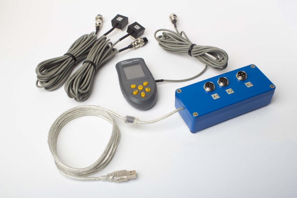
ਪੂਰੀ ਕਿੱਟ ਵਿੱਚ ਕੀ ਹੈ
€1,975 · ਪੂਰਾ ਕਿੱਟ, ਸਟਾਕ ਵਿੱਚ, VAT ਇਨਵੌਇਸ
- ਇੰਟਰਫੇਸ ਮਾਪ ਇਕਾਈ (USB, 2 ਚੈਨਲ)
- ਦੋ ਵਾਈਬ੍ਰੇਸ਼ਨ ਐਕਸੇਲੇਰੋਮੀਟਰ (4 m ਕੇਬਲ, 10 m ਵਿਕਲਪਿਕ)
- ਲੇਜ਼ਰ ਟੈਕੋਮੀਟਰ / ਆਪਟੀਕਲ ਫੇਜ਼ ਸੈਂਸਰ (50–500 mm)
- ਸੈਂਸਰ ਲਈ ਮੈਗਨੈਟਿਕ ਸਟੈਂਡ
- ਟਰਾਇਲ & ਸੁਧਾਰ ਵਜ਼ਨ ਲਈ ਡਿਜੀਟਲ ਸਕੇਲ
- Windows ਬੈਲੇਂਸਿੰਗ & ਵਿਸ਼ਲੇਸ਼ਣ ਸੌਫ਼ਟਵੇਅਰ
- ਪਲਾਸਟਿਕ ਟਰਾਂਸਪੋਰਟ ਕੇਸ
ਪੂਰੀ ਕਿੱਟ
ਯੂਨਿਟ · 2 ਸੈਂਸਰ · ਲੇਜ਼ਰ ਟੈਕੋਮੀਟਰ · ਮੈਗਨੈਟਿਕ ਸਟੈਂਡ · ਡਿਜੀਟਲ ਸਕੇਲ · ਸਾਫਟਵੇਅਰ · ਟ੍ਰਾਂਸਪੋਰਟ ਕੇਸ। ਬਾਕਸ ਵਿੱਚੋਂ ਹੀ ਟਰਬਾਈਨਾਂ ਨੂੰ ਸੰਤੁਲਿਤ ਕਰਨਾ ਸ਼ੁਰੂ ਕਰਨ ਲਈ ਲੋੜੀਂਦੀ ਹਰ ਚੀਜ਼।
OEM ਸੈੱਟ
ਯੂਨਿਟ · 2 ਸੈਂਸਰ · ਲੇਜ਼ਰ ਟੈਕੋਮੀਟਰ · ਸਾਫਟਵੇਅਰ। ਉਹਨਾਂ ਇੰਟੀਗ੍ਰੇਟਰਾਂ ਲਈ ਜਿਨ੍ਹਾਂ ਕੋਲ ਪਹਿਲਾਂ ਹੀ ਸਟੈਂਡ, ਸਕੇਲ ਅਤੇ ਕੇਸ ਹੈ, ਜਾਂ ਜੋ ਯੂਨਿਟ ਨੂੰ ਬੈਲੇਂਸਿੰਗ ਮਸ਼ੀਨ ਵਿੱਚ ਸ਼ਾਮਲ ਕਰਦੇ ਹਨ।
| ਪੈਰਾਮੀਟਰ | ਮੁੱਲ |
|---|---|
| ਮਾਪ ਚੈਨਲ | 2 (ਸਿੰਗਲ- & ਟੂ-ਪਲੇਨ ਬੈਲੇਂਸਿੰਗ) |
| ਵਾਈਬ੍ਰੇਸ਼ਨ ਵੇਲੋਸਿਟੀ ਰੇਂਜ | 0.2–80 mm/s RMS |
| ਫ੍ਰੀਕੁਐਂਸੀ ਰੇਂਜ | 5–1000 Hz (≤10% ਐਂਪਲੀਟਿਊਡ ਗਲਤੀ 550 Hz ਤੋਂ ਉੱਪਰ) |
| ਮਾਪ ਸ਼ੁੱਧਤਾ | ਪੂਰੇ ਸਕੇਲ ਦਾ ±5% |
| ਵਿਧੀ | 3-ਰਨ ਇਨਫਲੂਐਂਸ-ਕੋਏਫੀਸ਼ੀਐਂਟ (1 ਜਾਂ 2 ਸੁਧਾਰ-ਪਲੇਨ) |
| ਵਿਸ਼ਲੇਸ਼ਣ | 1× 'ਤੇ ਐਂਪਲੀਟਿਊਡ & ਫੇਜ਼, FFT ਸਪੈਕਟ੍ਰਮ & ਵੇਵਫਾਰਮ, ਸੰਭਾਲੀਆਂ ਗਈਆਂ ਰਿਪੋਰਟਾਂ |
| ਲੈਪਟਾਪ | ਸ਼ਾਮਲ ਨਹੀਂ (Windows PC, ਬੇਨਤੀ 'ਤੇ ਉਪਲਬਧ) |
ਫੀਲਡ ਵਿੱਚ ਟਰਬਾਈਨ & ਟਰਬੋਚਾਰਜਰ ਬੈਲੈਂਸਿੰਗ
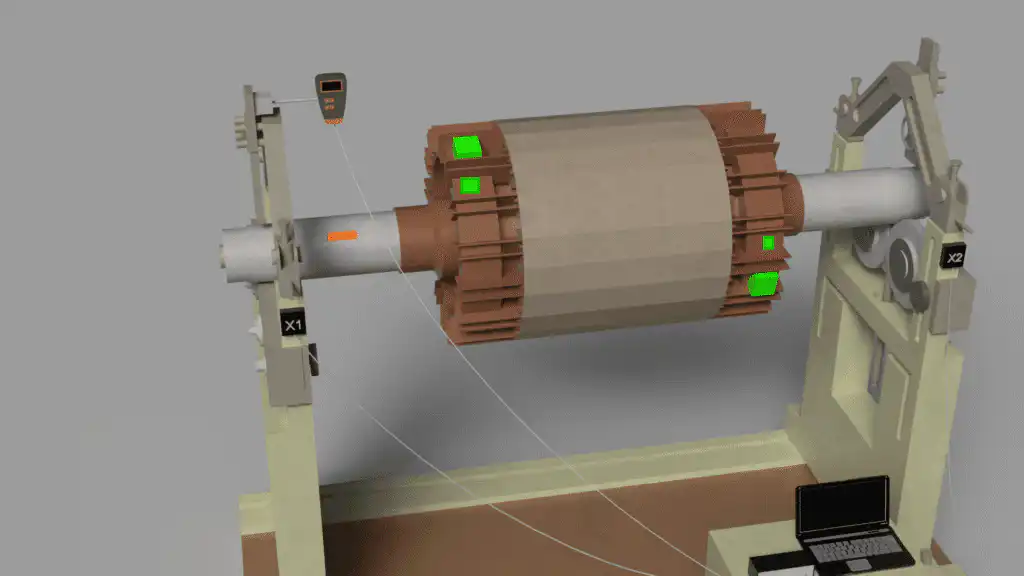
ਬੈਲੈਂਸਿੰਗ ਸੈੱਟਅੱਪ 'ਤੇ ਰੋਟਰ
Balanset-1A ਨਾਲ ਦੋ-ਪਲੇਨ ਫੀਲਡ ਬੈਲੈਂਸਿੰਗ ਲਈ ਯੰਤਰਿਤ ਇੱਕ ਹਾਈ-ਸਪੀਡ ਟਰਬੋ ਰੋਟਰ।
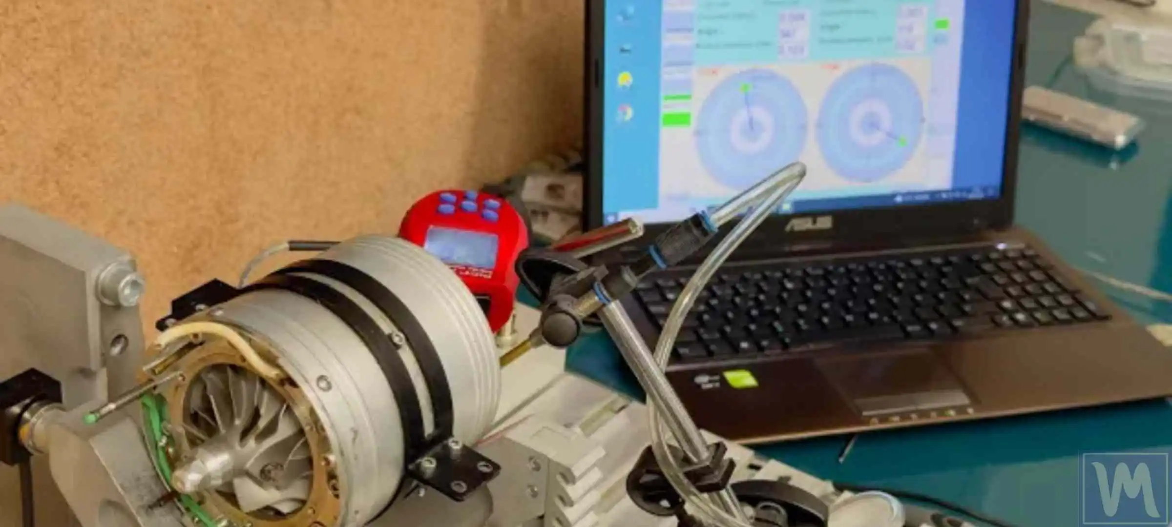
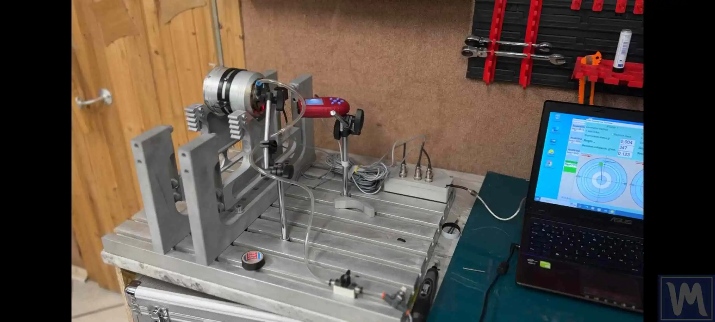
ਬੇਅਰਿੰਗ 'ਤੇ ਵਾਈਬ੍ਰੇਸ਼ਨ ਮਾਪ
ਬੇਅਰਿੰਗ 'ਤੇ ਸੈਂਸਰ ਅਤੇ ਲੇਜ਼ਰ ਟੈਕੋ ਸੰਚਾਲਨ ਸਪੀਡ 'ਤੇ 1× ਐਂਪਲੀਟਿਊਡ ਅਤੇ ਫੇਜ਼ ਨੂੰ ਕੈਪਚਰ ਕਰਦੇ ਹਨ।
ਫੀਲਡ ਬੈਲੇਂਸਿੰਗ ਬਨਾਮ ਬੈਲੇਂਸਿੰਗ ਮਸ਼ੀਨ — ਕਿਹੜਾ ਸਹੀ ਹੈ?
| ਮਾਪਦੰਡ | ਫੀਲਡ ਬੈਲੇਂਸਿੰਗ (Balanset-1A) | ਵਰਕਸ਼ਾਪ ਬੈਲੈਂਸਿੰਗ ਮਸ਼ੀਨ |
|---|---|---|
| ਰੋਟਰ ਹਟਾਉਣਾ ਲੋੜੀਂਦਾ ਹੈ | ਨਹੀਂ — ਥਾਂ 'ਤੇ ਹੀ ਸੰਤੁਲਿਤ | ਹਾਂ — ਪੂਰੀ ਤਰ੍ਹਾਂ ਖੋਲ੍ਹਣਾ |
| ਅਸਲ ਸੰਚਾਲਨ ਸਥਿਤੀਆਂ | ਹਾਂ — ਅਸਲ ਸਪੀਡ, ਅਸਲ ਬੇਅਰਿੰਗ | ਨਹੀਂ — ਘੱਟ ਸਪੀਡ, ਵੱਖਰੇ ਸਪੋਰਟ |
| ਡਾਊਨਟਾਈਮ | ਘੰਟਿਆਂ ਤੋਂ ਇੱਕ ਸ਼ਿਫਟ ਤੱਕ | ਕੁਝ ਦਿਨਾਂ ਤੋਂ ਹਫ਼ਤਿਆਂ ਤੱਕ |
| ਫਲੈਕਸੀਬਲ ਰੋਟਰ ਪ੍ਰਭਾਵਾਂ ਨੂੰ ਕੈਪਚਰ ਕੀਤਾ ਗਿਆ | ਹਾਂ — ਸਪੀਡ 'ਤੇ ਝੁਕਾਅ ਸ਼ਾਮਲ | ਘੱਟ-ਸਪੀਡ ਸ਼ਾਪ 0a30ਨ 'ਤੇ ਨਹੀਂ |
| ISO 20816 ਵਾਈਬ੍ਰੇਸ਼ਨ ਤਸਦੀਕ | ਪ੍ਰਕਿਰਿਆ ਵਿੱਚ ਸ਼ਾਮਲ | ਦੁਬਾਰਾ-ਅਸੈਂਬਲੀ ਤੋਂ ਬਾਅਦ ਵੱਖਰਾ ਕਦਮ |
| ਦੋ-ਪਲੇਨ ਸੁਧਾਈ | ਹਾਂ (ਦੋਵੇਂ ਪਲੇਨ ਇੱਕੋ ਸਮੇਂ) | ਹਾਂ |
| ਪੋਰਟੇਬਲ — ਕੋਈ ਵੀ ਸਾਈਟ | ਹਾਂ — ਕੈਰੀ ਕੇਸ ਵਿੱਚ ਫਿੱਟ ਹੁੰਦਾ ਹੈ | ਸਿਰਫ਼ ਸਥਿਰ ਵਰਕਸ਼ਾਪ |
| ਪ੍ਰਤੀ ਜੌਬ ਆਮ ਲਾਗਤ | ਘੱਟ (ਕੋਈ ਟ੍ਰਾਂਸਪੋਰਟ ਨਹੀਂ, ਕੋਈ ਕ੍ਰੇਨ ਨਹੀਂ) | ਵੱਧ (ਲੌਜਿਸਟਿਕਸ + ਵਰਕਸ਼ਾਪ ਸਮਾਂ) |
ਮੁਫ਼ਤ ਟਰਬਾਈਨ ਕੈਲਕੂਲੇਟਰ
ਟਰਬਾਈਨ ਬੈਲੰਸਿੰਗ FAQ
ਕੀ ਟਰਬਾਈਨ ਰੋਟਰ ਨੂੰ ਫੀਲਡ ਵਿੱਚ ਬੈਲੰਸ ਕੀਤਾ ਜਾ ਸਕਦਾ ਹੈ, ਜਾਂ ਇਸਨੂੰ ਬੈਲੰਸਿੰਗ ਮਸ਼ੀਨ ਦੀ ਲੋੜ ਹੈ?
ਮੇਰੀ ਟਰਬਾਈਨ ਲਈ ISO 20816 ਦਾ ਕਿਹੜਾ ਹਿੱਸਾ ਲਾਗੂ ਹੁੰਦਾ ਹੈ?
ਟਰਬੋਚਾਰਜਰ ਨੂੰ ਕਿਹੜੇ ਬੈਲੰਸ ਗ੍ਰੇਡ ਦੀ ਲੋੜ ਹੈ?
ਹਰ ਵੱਡੇ ਓਵਰਹਾਲ ਤੋਂ ਬਾਅਦ ਮੇਰੀ ਟਰਬਾਈਨ ਓਵਰ-ਵਾਈਬ੍ਰੇਸ਼ਨ 'ਤੇ ਟ੍ਰਿਪ ਹੋ ਜਾਂਦੀ ਹੈ — ਕਿਉਂ?
ਕੀ ਬੈਲਾਂਸੈੱਟ-1A ISO 20816 ਦੇ ਅਨੁਸਾਰ ਬੇਅਰਿੰਗ-ਹਾਊਸਿੰਗ ਵਾਈਬ੍ਰੇਸ਼ਨ ਮਾਪ ਸਕਦਾ ਹੈ?
ਮੈਨੂੰ ਕਿਵੇਂ ਪਤਾ ਲੱਗੇ ਕਿ ਇੱਕ ਪਲੇਨ ਵਿੱਚ ਬੈਲੰਸ ਕਰਨਾ ਹੈ ਜਾਂ ਦੋ ਵਿੱਚ?
ਸਿਧਾਂਤ ਸਿੱਖੋ
ਆਪਣੀ ਟਰਬਾਈਨ ਦਾ ਮੁਲਾਂਕਣ ਕਰੋ ਅਤੇ ਇਸਨੂੰ ਬੈਲੰਸ ਕਰੋ — ISO ਮਿਆਰ ਦੇ ਅਨੁਸਾਰ
ਬੈਲਾਂਸੈੱਟ-1A ISO 20816 ਦੇ ਅਨੁਸਾਰ ਬੇਅਰਿੰਗ-ਹਾਊਸਿੰਗ ਵਾਈਬ੍ਰੇਸ਼ਨ ਮਾਪਦਾ ਹੈ ਅਤੇ ISO 21940-11 ਦੇ ਅਨੁਸਾਰ ਦੋ-ਪਲੇਨ ਫੀਲਡ ਬੈਲੰਸਿੰਗ ਕਰਦਾ ਹੈ — ਇੱਕ ਪੋਰਟੇਬਲ ਯੰਤਰ ਵਿੱਚ ਤੁਹਾਨੂੰ ਨਿਦਾਨ ਅਤੇ ਸੁਧਾਰ ਦੋਵੇਂ ਦਿੰਦਾ ਹੈ, ਹਰੇਕ ਕੰਮ ਲਈ ਦਸਤਾਵੇਜ਼ੀ ਨਤੀਜੇ ਦੇ ਨਾਲ।
