
పోర్టబుల్ బ్యాలెన్సర్ "BALANSET-1A"
డ్యూయల్-ఛానెల్ PC-ఆధారిత డైనమిక్ బ్యాలెన్సింగ్ సిస్టమ్
ఆపరేషన్ మాన్యువల్
రివ. 1.56 మే 2023
2023 | ఎస్టోనియా, నార్వా
భద్రతా గమనిక: ఈ పరికరం EU భద్రతా ప్రమాణాలకు అనుగుణంగా ఉంటుంది. Class 2 లేజర్ ఉత్పత్తి. తిరిగే యంత్రసామగ్రి భద్రతా విధానాలను పాటించండి. పూర్తి భద్రతా సమాచారం దిగువన చూడండి →
1. బ్యాలెన్సింగ్ సిస్టమ్ అవలోకనం
Balanset-1A బ్యాలెన్సర్ ఫ్యాన్లు, గ్రైండింగ్ వీల్స్, స్పిండిల్స్, క్రషర్లు, పంపులు మరియు ఇతర తిరిగే యంత్రసామగ్రికి సింగిల్- మరియు టూ-ప్లేన్ డైనమిక్ బ్యాలెన్సింగ్ సేవలను అందిస్తుంది.
Balanset-1A బ్యాలెన్సర్లో రెండు వైబ్రోసెన్సర్లు (యాక్సిలెరోమీటర్లు), లేజర్ ఫేజ్ సెన్సర్ (టాకోమీటర్), ప్రీ-యాంప్లిఫయర్లు, ఇంటిగ్రేటర్లు మరియు ADC అక్విజిషన్ మాడ్యూల్తో కూడిన 2-చానెల్ USB ఇంటర్ఫేస్ యూనిట్ మరియు Windows ఆధారిత బ్యాలెన్సింగ్ సాఫ్ట్వేర్ ఉన్నాయి. Balanset-1A కు నోట్బుక్ లేదా ఇతర Windows (WinXP...Win11, 32 లేదా 64bit) అనుకూల PC అవసరం.
బ్యాలెన్సింగ్ సాఫ్ట్వేర్ సింగిల్-ప్లేన్ మరియు టూ-ప్లేన్ బ్యాలెన్సింగ్కు సరైన బ్యాలెన్సింగ్ పరిష్కారాన్ని ఆటోమేటిక్గా అందిస్తుంది. Balanset-1A కంపన నిపుణులు కాని వారికి ఉపయోగించడానికి సులభం.
అన్ని బ్యాలెన్సింగ్ ఫలితాలు ఆర్కైవ్లో సేవ్ చేయబడతాయి మరియు రిపోర్ట్లను సృష్టించడానికి ఉపయోగించవచ్చు.
ముఖ్య లక్షణాలు
ఉపయోగించడం సులభం
- • వినియోగదారు ఎంచుకోదగిన ట్రయల్ మాస్
- • ట్రయల్ మాస్ వ్యాలిడిటీ పాప్అప్
- • మాన్యువల్ డేటా ఇన్పుట్
కొలత సామర్థ్యాలు
- • RPM, వ్యాప్తి మరియు ఫేజ్
- • FFT స్పెక్ట్రమ్ విశ్లేషణ
- • వేవ్ఫారమ్ మరియు స్పెక్ట్రమ్ డిస్ప్లే
- • డ్యూయల్-ఛానెల్ ఏకకాల డేటా
అధునాతన విధులు
- • సేవ్ చేయబడిన ప్రభావ గుణకాలు
- • ట్రిమ్ బ్యాలెన్సింగ్
- • మాండ్రెల్ ఎక్సెంట్రిసిటీ గణన
- • ISO 1940 టాలరెన్స్ లెక్కింపు
డేటా నిర్వహణ
- • అపరిమిత బ్యాలెన్సింగ్ డేటా నిల్వ
- • వైబ్రేషన్ వేవ్ఫారమ్ నిల్వ
- • ఆర్కైవ్ మరియు నివేదికలు
గణన సాధనాలు
- • సరిదిద్దే బరువు విభజన లెక్కింపు
- • డ్రిల్ గణన
- • సరిదిద్దే తలాల మార్పు
- • పోలార్ గ్రాఫ్ దృశ్యీకరణ
విశ్లేషణ ఎంపికలు
- • ట్రయల్ బరువులను తొలగించడం లేదా అలాగే ఉంచడం
- • రన్డౌన్ చార్టులు (ప్రయోగాత్మకం)
2. స్పెసిఫికేషన్
| పరామితి | స్పెసిఫికేషన్ |
|---|---|
| కంపన వేగం యొక్క రూట్-మీన్-స్క్వేర్ విలువ (RMS) యొక్క కొలత పరిధి, mm/sec (1x కంపనం కోసం) | 0.02 నుండి 80 వరకు |
| కంపన వేగం యొక్క RMS కొలత యొక్క పౌనఃపున్య పరిధి, Hz | 5 నుండి 1000 వరకు (యాంప్లిట్యూడ్ లోపం ≤10% 5 నుండి 550 Hz వరకు; 550 నుండి 1000 Hz వరకు 20% వరకు) |
| కరెక్షన్ ప్లేన్ల సంఖ్య | 1 లేదా 2 |
| భ్రమణ పౌనఃపున్యం కొలత పరిధి, rpm | 100 – 100000 |
| కంపన ఫేజ్ కొలత పరిధి, కోణీయ డిగ్రీలు | 0 నుండి 360 వరకు |
| కంపన ఫేజ్ కొలతలో దోషం, కోణీయ డిగ్రీలు | ± 1 |
| RMS కంపన వేగం యొక్క కొలత ఖచ్చితత్వం | ±(0.1 + 0.1×Vకొలిచిన) mm/sec |
| భ్రమణ పౌనఃపున్యం యొక్క కొలత ఖచ్చితత్వం | ±(1 + 0.005×Nకొలిచిన) rpm |
| వైఫల్యాల మధ్య సగటు సమయం (MTBF), గంటలు, కనీసం | 1000 |
| సగటు సేవా జీవితకాలం, సంవత్సరాలు, కనీసం | 6 |
| కొలతలు (హార్డ్ కేస్లో), cm | 39*33*13 |
| ద్రవ్యరాశి, kg | <5 |
| వైబ్రేటర్ సెన్సర్ యొక్క మొత్తం కొలతలు, mm, గరిష్టం | 25*25*20 |
| వైబ్రేటర్ సెన్సర్ యొక్క బరువు, kg, గరిష్టం | 0.04 |
|
పని పరిస్థితులు: - ఉష్ణోగ్రత పరిధి: 5°C నుండి 50°C వరకు - సాపేక్ష తేమ: < 85%, అసంతృప్తం - తీవ్రమైన విద్యుదయస్కాంత క్షేత్రం & తీవ్రమైన దెబ్బ లేకుండా |
|
3. ప్యాకేజీ
Balanset-1A బ్యాలెన్సర్లో రెండు సింగిల్-యాక్సిస్ యాక్సిలెరోమీటర్లు, లేజర్ ఫేజ్ రిఫరెన్స్ మార్కర్ (డిజిటల్ టాకోమీటర్), ప్రీ-యాంప్లిఫయర్లు, ఇంటిగ్రేటర్లు మరియు ADC అక్విజిషన్ మాడ్యూల్తో కూడిన 2-చానెల్ USB ఇంటర్ఫేస్ యూనిట్ మరియు Windows ఆధారిత బ్యాలెన్సింగ్ సాఫ్ట్వేర్ ఉన్నాయి.
డెలివరీ సెట్
| వివరణ | సంఖ్య | గమనిక |
|---|---|---|
| USB ఇంటర్ఫేస్ యూనిట్ | 1 | |
| లేజర్ ఫేజ్ రిఫరెన్స్ మార్కర్ (టాకోమీటర్) | 1 | |
| సింగిల్-యాక్సిస్ యాక్సిలెరోమీటర్లు | 2 | |
| మాగ్నెటిక్ స్టాండ్ | 1 | |
| డిజిటల్ తూనిక యంత్రాలు | 1 | |
| రవాణా కోసం హార్డ్ కేస్ | 1 | |
| "Balanset-1A". వినియోగదారు మాన్యువల్. | 1 | |
| బ్యాలెన్సింగ్ సాఫ్ట్వేర్తో ఫ్లాష్ డిస్క్ | 1 |
4. బ్యాలెన్సింగ్ సూత్రాలు
4.1. "Balanset-1A"లో (చిత్రం 4.1) USB ఇంటర్ఫేస్ యూనిట్ ఉంటుంది (1), రెండు యాక్సిలెరోమీటర్లు (2) మరియు (3), ఫేజ్ రిఫరెన్స్ మార్కర్ (4) మరియు పోర్టబుల్ PC (సరఫరా చేయబడదు) (5).
డెలివరీ సెట్లో మాగ్నెటిక్ స్టాండ్ కూడా ఉంటుంది (6) ) ఫేజ్ రిఫరెన్స్ మార్కర్ మరియు డిజిటల్ స్కేల్స్ను మౌంట్ చేయడానికి ఉపయోగించబడుతుంది 7.
X1 మరియు X2 కనెక్టర్లు కంపన సెన్సార్లను వరుసగా 1 మరియు 2 కొలత చానల్లకు కనెక్ట్ చేయడానికి ఉద్దేశించబడ్డాయి, మరియు X3 కనెక్టర్ ఫేజ్ రెఫరెన్స్ మార్కర్ను కనెక్ట్ చేయడానికి ఉపయోగించబడుతుంది.
USB కేబుల్ పవర్ సప్లైని అందిస్తుంది మరియు USB ఇంటర్ఫేస్ యూనిట్ను కంప్యూటర్కు కనెక్ట్ చేస్తుంది.

చిత్రం 4.1. "Balanset-1A" యొక్క డెలివరీ సెట్
యాంత్రిక కంపనాలు వైబ్రేషన్ సెన్సార్ అవుట్పుట్ వద్ద కంపన త్వరణానికి అనుపాతంలో విద్యుత్ సిగ్నల్ను ఉత్పత్తి చేస్తాయి. ADC మాడ్యూల్ నుండి డిజిటలైజ్ చేయబడిన సిగ్నల్లు USB ద్వారా పోర్టబుల్ PCకి బదిలీ చేయబడతాయి ( (5). ఫేజ్ రిఫరెన్స్ మార్కర్ భ్రమణ పౌనఃపున్యం మరియు కంపన ఫేజ్ కోణాన్ని లెక్కించడానికి ఉపయోగించే పల్స్ సిగ్నల్ను ఉత్పత్తి చేస్తుంది. Windows ఆధారిత సాఫ్ట్వేర్ సింగిల్-ప్లేన్ మరియు టూ-ప్లేన్ బ్యాలెన్సింగ్, స్పెక్ట్రమ్ విశ్లేషణ, చార్ట్లు, నివేదికలు, ఇన్ఫ్లుయెన్స్ కోఎఫిషియంట్ల నిల్వకు పరిష్కారం అందిస్తుంది
5. భద్రతా జాగ్రత్తలు
⚡ హెచ్చరిక - విద్యుత్ భద్రత
5.1. 220V పై పనిచేసేటప్పుడు విద్యుత్ సేఫ్టీ నియమాలు పాటించాలి. 220 V కి కనెక్ట్ చేయబడినప్పుడు డివైజ్ను మరమ్మత్తు చేయడం అనుమతించబడదు.
5.2. మీరు పరికరాన్ని తక్కువ నాణ్యత గల AC విద్యుత్ వాతావరణంలో లేదా నెట్వర్క్ జోక్యం ఉన్న చోట ఉపయోగిస్తే, కంప్యూటర్ బ్యాటరీ ప్యాక్ నుండి స్వతంత్ర విద్యుత్ సరఫరాను ఉపయోగించడం సిఫారసు చేయబడుతుంది.
⚠️ తిరిగే పరికరాలకు అదనపు భద్రతా అవసరాలు
- !మెషీన్ లాకౌట్: సెన్సార్లను అమర్చే ముందు సరైన లాకౌట్/ట్యాగౌట్ విధానాలను ఎల్లప్పుడూ అనుసరించండి
- !వ్యక్తిగత రక్షణ సాధనాలు: భద్రతా కళ్ళద్దాలు, శ్రవణ రక్షణ ధరించండి మరియు తిరిగే యంత్రాల దగ్గర వదులుగా ఉన్న దుస్తులు ధరించకుండా జాగ్రత్తపడండి
- !సురక్షిత ఇన్స్టాలేషన్: అన్ని సెన్సర్లు మరియు కేబుళ్ళు గట్టిగా బిగించబడి ఉన్నాయని మరియు తిరిగే భాగాలచే పట్టుకోబడవని నిర్ధారించుకోండి
- !అత్యవసర విధానాలు: అత్యవసర స్టాప్ల స్థానం మరియు షట్డౌన్ విధానాలు తెలుసుకోండి
- !శిక్షణ: తిరిగే యంత్రాలపై బ్యాలెన్సింగ్ పరికరాలను నిర్వహించడానికి శిక్షణ పొందిన సిబ్బంది మాత్రమే అర్హులు
6. సాఫ్ట్వేర్ మరియు హార్డ్వేర్ సెట్టింగులు
6.1. USB డ్రైవర్లు మరియు బ్యాలెన్సింగ్ సాఫ్ట్వేర్ ఇన్స్టాలేషన్
పనిచేసే ముందు డ్రైవర్లు మరియు బ్యాలెన్సింగ్ సాఫ్ట్వేర్ను ఇన్స్టాల్ చేయండి.
ఫోల్డర్లు మరియు ఫైళ్ళ జాబితా
ఇన్స్టాలేషన్ డిస్క్ (ఫ్లాష్ డ్రైవ్) ఈ క్రింది ఫైల్లు మరియు ఫోల్డర్లను కలిగి ఉంటుంది:
- Bs1Av###Setup – "Balanset-1A" బ్యాలెన్సింగ్ సాఫ్ట్వేర్ ఉన్న ఫోల్డర్ (### – వెర్షన్ నంబర్)
- ArdDrv – USB డ్రైవర్లు
- EBalancer_manual.pdf – ఈ మాన్యువల్
- Bal1Av###Setup.exe – సెటప్ ఫైల్. ఈ ఫైల్లో పైన పేర్కొన్న అన్ని ఆర్కైవ్ చేయబడిన ఫైళ్ళు మరియు ఫోల్డర్లు ఉన్నాయి. ### – "Balanset-1A" సాఫ్ట్వేర్ యొక్క వెర్షన్.
- Ebalanc.cfg – సెన్సిటివిటీ విలువ
- Bal.ini – కొంత ఇనిషియలైజేషన్ డేటా
సాఫ్ట్వేర్ ఇన్స్టాలేషన్ విధానం
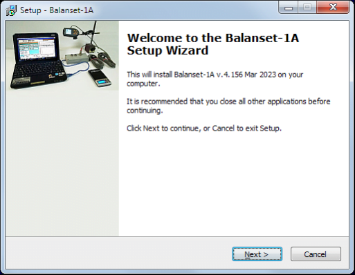
డ్రైవర్లు మరియు ప్రత్యేక సాఫ్ట్వేర్ను ఇన్స్టాల్ చేయడానికి ఫైల్ను రన్ చేయండి Bal1Av###Setup.exe మరియు « బటన్లను నొక్కి సెటప్ సూచనలను అనుసరించండితదుపరి», «ОК» మొదలైనవి
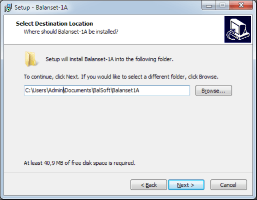
సెటప్ ఫోల్డర్ను ఎంచుకోండి. సాధారణంగా ఇచ్చిన ఫోల్డర్ను మార్చకూడదు.
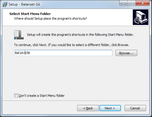
ఆ తర్వాత ప్రోగ్రామ్ ప్రోగ్రామ్ గ్రూప్ మరియు డెస్క్టాప్ ఫోల్డర్లను పేర్కొనమని కోరుతుంది. బటన్ను నొక్కండి తదుపరి.
ఇన్స్టాలేషన్ పూర్తి చేయడం
- ✓సెన్సార్లను పరిశీలించబడే లేదా బ్యాలెన్స్ చేయబడే మెకానిజంపై ఇన్స్టాల్ చేయండి (సెన్సార్లను ఎలా ఇన్స్టాల్ చేయాలో వివరణాత్మక సమాచారం Annex 1 లో ఇవ్వబడింది)
- ✓కంపన సెన్సార్లు 2 మరియు 3 ను X1 మరియు X2 ఇన్పుట్లకు, మరియు ఫేజ్ కోణ సెన్సార్ను USB ఇంటర్ఫేస్ యూనిట్ యొక్క X3 ఇన్పుట్కు కనెక్ట్ చేయండి.
- ✓USB ఇంటర్ఫేస్ యూనిట్ను కంప్యూటర్ యొక్క USB-పోర్ట్కు కనెక్ట్ చేయండి.
- ✓AC విద్యుత్ సరఫరాను ఉపయోగిస్తున్నప్పుడు కంప్యూటర్ను పవర్ మెయిన్కు కనెక్ట్ చేయండి. పవర్ సరఫరాను 220 V, 50 Hz కు కనెక్ట్ చేయండి.
- ✓డెస్క్టాప్పై "Balanset-1A" షార్ట్కట్పై క్లిక్ చేయండి.
7. బ్యాలెన్సింగ్ సాఫ్ట్వేర్
7.1. సాధారణ సమాచారం
ప్రారంభ విండో
"Balanset-1A" ప్రోగ్రామ్ను అమలు చేసినప్పుడు, చిత్రం 7.1 లో చూపిన ప్రారంభ విండో కనిపిస్తుంది.

చిత్రం 7.1. "Balanset-1A" యొక్క ప్రారంభ విండో
ప్రారంభ విండోలో వాటిపై క్లిక్ చేసినప్పుడు నిర్వహించబడే ఫంక్షన్ల పేర్లతో 9 బటన్లు ఉన్నాయి.
F1-«గురించి»
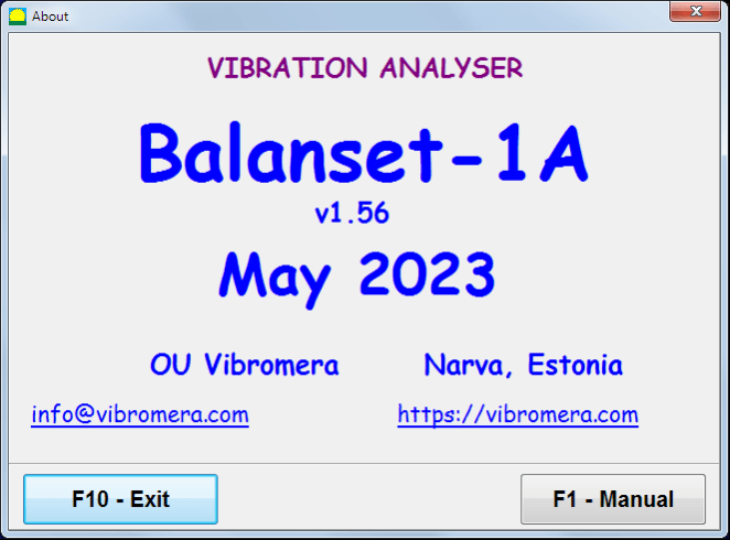
చిత్రం 7.2. F1-«గురించి» విండో
F2-«ఒకే తలం», F3-«రెండు తలాలు»
నొక్కడం "F2- సింగిల్-ప్లేన్" (లేదా F2 కంప్యూటర్ కీబోర్డ్పై ఫంక్షన్ కీ) చానెల్పై కంపన కొలతను ఎంచుకుంటుంది X1.
ఈ బటన్ను క్లిక్ చేసిన తర్వాత, కంప్యూటర్ డిస్ప్లే Fig. 7.1 లో చూపిన డయాగ్రామ్ను చూపిస్తుంది, ఇది మొదటి కొలత ఛానల్పై మాత్రమే కంపనాన్ని కొలవడం ప్రక్రియను (లేదా సింగిల్ ప్లేన్లో బ్యాలెన్సింగ్ ప్రక్రియను) వివరిస్తుంది.
"F3-రెండు-ప్లేన్" (లేదా F3 కంప్యూటర్ కీబోర్డ్పై ఫంక్షన్ కీ) రెండు ఛానల్లపై కంపన కొలతల మోడ్ను ఎంచుకుంటుంది X1 మరియు X2 ఒకేసారి. (చిత్రం 7.3.)
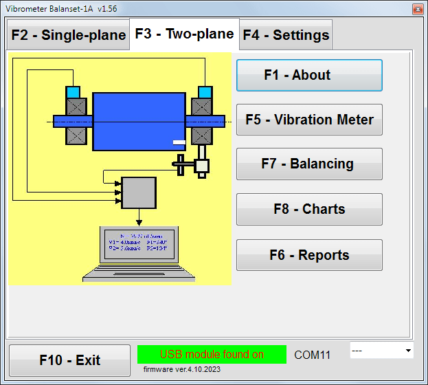
చిత్రం 7.3. "Balanset-1A" యొక్క ప్రారంభ విండో. టూ-ప్లేన్ బ్యాలెన్సింగ్.
F4 – «సెట్టింగులు»
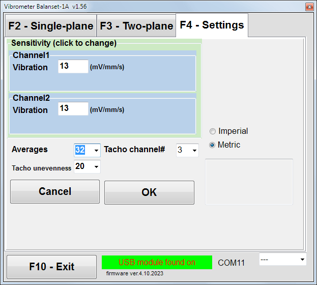
చిత్రం 7.4. "సెట్టింగులు" విండో
ఈ విండోలో మీరు కొన్ని Balanset-1A సెట్టింగ్లను మార్చవచ్చు.
- సంవేదనశీలత. నామమాత్రపు విలువ 13 mV / mm/s.
సెన్సార్ల సెన్సిటివిటీ కోఎఫీషియంట్లను మార్చడం సెన్సార్లను మార్చినప్పుడు మాత్రమే అవసరం!
గమనిక!
మీరు సెన్సిటివిటీ కోఎఫిషియెంట్ నమోదు చేసినప్పుడు దాని భిన్న భాగాన్ని పూర్ణాంక భాగం నుండి దశాంశ బిందువుతో (చిహ్నం ",") వేరు చేయాలి.
- సగటు లెక్కింపు – సగటు గణన సంఖ్య (మరింత ఖచ్చితత్వం కోసం డేటాను సగటు చేసే రోటర్ భ్రమణాల సంఖ్య)
- టాకో ఛానల్# - ఏ ఛానెల్కు Tacho కనెక్ట్ చేయబడిందో. డిఫాల్ట్గా - 3వ ఛానెల్.
- అసమానత - సమీప tacho పల్స్ల మధ్య వ్యవధిలో తేడా, ఇది హెచ్చరికను ఇస్తుంది "టాకోమీటర్ వైఫల్యం"
- ఇంపీరియల్/మెట్రిక్ - యూనిట్ల వ్యవస్థను ఎంచుకోండి.
Com పోర్ట్ నంబర్ ఆటోమేటిక్గా అసైన్ చేయబడుతుంది.
F5 – «వైబ్రేషన్ మీటర్»
ఈ బటన్ను (లేదా ఫంక్షన్ కీని) నొక్కినప్పుడు F5 కంప్యూటర్ కీబోర్డ్పై) బటన్ల స్థితిని బట్టి వర్చువల్ వైబ్రేషన్ మీటర్ యొక్క ఒకటి లేదా రెండు కొలత ఛానెళ్లలో వైబ్రేషన్ కొలత మోడ్ను యాక్టివేట్ చేస్తుంది “F2-సింగిల్-ప్లేన్", "F3-రెండు-ప్లేన్".
F6 – «రిపోర్టులు»
ఈ బటన్ను నొక్కడం (లేదా F6 కంప్యూటర్ కీబోర్డ్పై ఫంక్షన్ కీ) బ్యాలెన్సింగ్ ఆర్కైవ్ను ఆన్ చేస్తుంది, దీని నుండి నిర్దిష్ట మెకానిజం (రోటర్) కోసం బ్యాలెన్సింగ్ ఫలితాలతో రిపోర్ట్ను ప్రింట్ చేయవచ్చు.
F7 – «బ్యాలెన్సింగ్»
ఈ బటన్ను (లేదా మీ కీబోర్డ్పై F7 ఫంక్షన్ కీని) నొక్కడం వలన, బటన్లను నొక్కడం ద్వారా ఎంపిక చేసిన కొలత మోడ్ను బట్టి ఒకటి లేదా రెండు కరెక్షన్ ప్లేన్లలో బ్యాలెన్సింగ్ మోడ్ యాక్టివేట్ అవుతుంది “F2-సింగిల్-ప్లేన్", "F3-రెండు-ప్లేన్".
F8 – «చార్ట్లు»
ఈ బటన్ను నొక్కడం (లేదా F8 కంప్యూటర్ కీబోర్డ్లోని ఫంక్షన్ కీ) గ్రాఫికల్ వైబ్రేషన్ మీటర్ను ప్రారంభిస్తుంది, దీని అమలు డిస్ప్లేపై కంపనం యొక్క టైమ్ ఫంక్షన్ గ్రాఫిక్స్తో పాటు ఆంప్లిట్యూడ్ మరియు ఫేజ్ యొక్క డిజిటల్ విలువలను ఏకకాలంలో చూపిస్తుంది.
F10 – «నిష్క్రమించు»
ఈ బటన్ను నొక్కడం (లేదా F10 కంప్యూటర్ కీబోర్డ్లోని ఫంక్షన్ కీ) "Balanset-1A" ప్రోగ్రామ్ను ముగిస్తుంది.
7.2. "వైబ్రేషన్ మీటర్"
"వైబ్రేషన్ మీటర్" మోడ్లో పని చేయడానికి ముందు, మెషీన్పై వైబ్రేషన్ సెన్సార్లను అమర్చి వాటిని USB ఇంటర్ఫేస్ యూనిట్ యొక్క X1 మరియు X2 కనెక్టర్లకు వరుసగా కనెక్ట్ చేయండి. Tacho సెన్సార్ను USB ఇంటర్ఫేస్ యూనిట్ యొక్క X3 ఇన్పుట్కు కనెక్ట్ చేయాలి.

చిత్రం 7.5 USB ఇంటర్ఫేస్ యూనిట్
Tacho పనిచేయడానికి రోటర్ ఉపరితలంపై రిఫ్లెక్టివ్ టేప్ అతికించండి.

చిత్రం 7.6. రిఫ్లెక్టివ్ టేప్.
సెన్సార్ల ఇన్స్టాలేషన్ మరియు కాన్ఫిగరేషన్ కోసం సిఫార్సులు Annex 1 లో ఇవ్వబడ్డాయి.
వైబ్రేషన్ మీటర్ మోడ్లో కొలత ప్రారంభించడానికి ప్రోగ్రామ్ యొక్క ప్రారంభ విండోలో "F5 – వైబ్రేషన్ మీటర్" బటన్ను క్లిక్ చేయండి (చిత్రం 7.1 చూడండి).
వైబ్రేషన్ మీటర్ విండో కనిపిస్తుంది (చిత్రం 7.7 చూడండి)

చిత్రం 7.7. కంపన మీటర్ మోడ్. వేవ్ మరియు స్పెక్ట్రమ్.
వైబ్రేషన్ కొలతలు ప్రారంభించడానికి "F9 – రన్" (లేదా ఫంక్షన్ కీని నొక్కండి F9 కీబోర్డ్పై).
If ట్రిగ్గర్ మోడ్ ఆటో చెక్ చేయబడితే – వైబ్రేషన్ కొలతల ఫలితాలు తెరపై కాలానుగుణంగా ప్రదర్శించబడతాయి.
మొదటి మరియు రెండవ ఛానెళ్లలో వైబ్రేషన్ను ఏకకాలంలో కొలిచినప్పుడు, పదాల కింద ఉన్న విండోలు “ప్లేన్ 1" మరియు "ప్లేన్ 2" నిండుతుంది.
“వైబ్రేషన్” మోడ్లో వైబ్రేషన్ కొలతను ఫేజ్ యాంగిల్ సెన్సార్ డిస్కనెక్ట్ చేయబడిన స్థితిలో కూడా నిర్వహించవచ్చు. ప్రోగ్రామ్ యొక్క ఇనీషియల్ విండోలో మొత్తం RMS వైబ్రేషన్ (V1s, V2s) మాత్రమే ప్రదర్శించబడుతుంది.
వైబ్రేషన్ మీటర్ మోడ్లో కింది సెట్టింగులు ఉన్నాయి
- RMS దిగువ, Hz – మొత్తం వైబ్రేషన్ యొక్క RMS లెక్కించడానికి అతి తక్కువ ఫ్రీక్వెన్సీ
- బ్యాండ్విడ్త్ - చార్ట్లో వైబ్రేషన్ ఫ్రీక్వెన్సీ బ్యాండ్విడ్త్
- సగటులు - మరింత కొలత ఖచ్చితత్వం కోసం సగటు సంఖ్య
"వైబ్రేషన్ మీటర్" మోడ్లో పనిని పూర్తి చేయడానికి "F10 – నిష్క్రమించు" బటన్ను క్లిక్ చేసి ప్రారంభ విండోకు తిరిగి వెళ్ళండి.

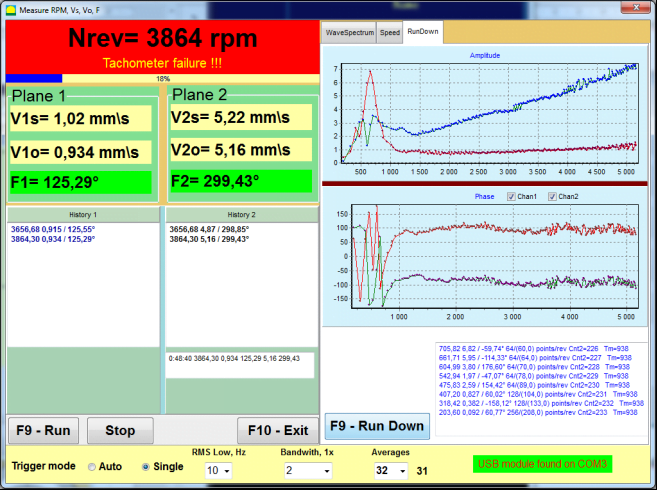
చిత్రం 7.8. కంపన మీటర్ మోడ్. భ్రమణ వేగం అసమానత, 1x కంపన తరంగ రూపం.
చిత్రం 7.9. కంపన మీటర్ మోడ్. రండౌన్ (బీటా వెర్షన్, వారంటీ లేదు!).
7.3 బ్యాలెన్సింగ్ విధానం
బ్యాలెన్సింగ్ అనేది మంచి సాంకేతిక స్థితిలో మరియు సరిగ్గా మౌంట్ చేయబడిన మెకానిజంల కోసం నిర్వహించబడుతుంది. లేకపోతే, బ్యాలెన్సింగ్ ముందు మెకానిజమ్ను మరమ్మతు చేయాలి, సరైన బేరింగ్లలో ఇన్స్టాల్ చేయాలి మరియు ఫిక్స్ చేయాలి. బ్యాలెన్సింగ్ ప్రక్రియకు అడ్డుపడే కాలుష్యాల నుండి రోటర్ను శుభ్రం చేయాలి.
బ్యాలెన్సింగ్ ముందు, ప్రధానంగా కంపనం 1x కంపనమే అని నిర్ధారించుకోవడానికి కంపన మీటర్ మోడ్లో (F5 బటన్) కంపనాన్ని కొలవండి.
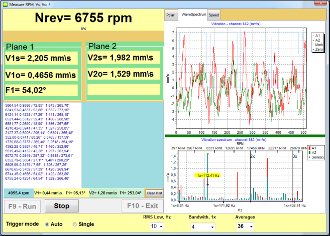
చిత్రం 7.10. కంపన మీటర్ మోడ్. మొత్తం (V1s,V2s) మరియు 1x (V1o,V2o) కంపనాన్ని తనిఖీ చేయడం.
మొత్తం వైబ్రేషన్ V1s (V2s) విలువ భ్రమణ ఫ్రీక్వెన్సీ వద్ద వైబ్రేషన్ పరిమాణానికి (1x వైబ్రేషన్) V1o (V2o) సమానంగా ఉంటే, మెకానిజమ్కు వైబ్రేషన్కు ప్రధాన కారణం రోటర్ అన్బ్యాలెన్స్ అని అనుమానించవచ్చు. మొత్తం వైబ్రేషన్ V1s (V2s) విలువ 1x వైబ్రేషన్ కాంపోనెంట్ V1o (V2o) కంటే చాలా ఎక్కువగా ఉంటే, మెకానిజమ్ స్థితిని తనిఖీ చేయడం సిఫారసు చేయబడింది – బేరింగ్ల స్థితి, బేస్పై దాని మౌంట్, భ్రమణ సమయంలో స్థిర భాగాలు మరియు రోటర్ మధ్య సంపర్కం లేదని నిర్ధారించుకోండి, మొదలైనవి.
కంపన మీటర్ మోడ్లో కొలవబడిన విలువల స్థిరత్వానికి కూడా దృష్టి పెట్టాలి – కొలత ప్రక్రియలో కంపనం యొక్క ఆంప్లిట్యూడ్ మరియు ఫేజ్ 10-15% కంటే ఎక్కువ మారకూడదు. లేకపోతే, మెకానిజం రెసొనెన్స్ డొమైన్కు దగ్గరగా పనిచేస్తుందని భావించవచ్చు. ఈ సందర్భంలో, రోటర్ యొక్క భ్రమణ వేగాన్ని మార్చండి, మరియు ఇది సాధ్యం కాకపోతే – ఫౌండేషన్పై మెషీన్ ఇన్స్టాలేషన్ షరతులను మార్చండి (ఉదాహరణకు, తాత్కాలికంగా స్ప్రింగ్ సపోర్ట్లపై ఉంచడం).
రోటర్ బ్యాలెన్సింగ్ కోసం ఇన్ఫ్లుయెన్స్ కోఎఫిషియెంట్ పద్ధతి బ్యాలెన్సింగ్ (3-రన్ పద్ధతి) ఉపయోగించాలి.
పరీక్షా భారం యొక్క కంపన మార్పుపై ప్రభావాన్ని, సవరణ భారాల యొక్క భారం మరియు స్థానం (కోణం) నిర్ణయించడానికి ట్రయల్ రన్లు నిర్వహించబడతాయి.
ముందుగా మెకానిజం యొక్క అసలు కంపనాన్ని నిర్ణయించండి (బరువు లేకుండా మొదటి స్టార్ట్), తర్వాత మొదటి ప్లేన్కు ట్రయల్ బరువును సెట్ చేసి రెండవ స్టార్ట్ చేయండి. తర్వాత, మొదటి ప్లేన్ నుండి ట్రయల్ బరువును తొలగించి, రెండవ ప్లేన్లో సెట్ చేసి మూడవ స్టార్ట్ చేయండి.
తర్వాత ప్రోగ్రామ్ స్క్రీన్పై సవరణ భారాల యొక్క భారం మరియు స్థానం (కోణం) ను లెక్కించి చూపిస్తుంది.
సింగిల్ ప్లేన్లో (స్టాటిక్) బ్యాలెన్సింగ్ చేసినప్పుడు, రెండవ స్టార్ట్ అవసరం లేదు.
ట్రయల్ బరువును రోటర్పై సౌకర్యవంతమైన ఏదైనా స్థానంలో అమర్చాలి, ఆ తర్వాత అసలు రేడియస్ను సెటప్ ప్రోగ్రామ్లో నమోదు చేయాలి.
(పొజిషన్ రేడియస్ గ్రాములలో * mm లో అసమతౌల్యత పరిమాణాన్ని లెక్కించడానికి మాత్రమే ఉపయోగించబడుతుంది)
ముఖ్యమైనది!
- కొలతలు మెకానిజం యొక్క స్థిరమైన భ్రమణ వేగంతో నిర్వహించబడాలి!
- సవరణ భారాలు ట్రయల్ భారాలతో సమానమైన రేడియస్పై ఇన్స్టాల్ చేయబడాలి!
ట్రయల్ బరవు యొక్క భారం ఎంపిక చేయబడుతుంది, తద్వారా దాని ఇన్స్టాలేషన్ తర్వాత ఫేజ్ (> 20-30°) మరియు (20-30%) కంపన ఆంప్లిట్యూడ్ మార్పు గణనీయంగా ఉంటుంది. మార్పులు చాలా చిన్నవిగా ఉంటే, తదుపరి లెక్కలలో తప్పు గణనీయంగా పెరుగుతుంది. ఫేజ్ మార్క్తో సమానమైన స్థానంలో (సమాన కోణం) ట్రయల్ బరవును సెట్ చేయడం సౌకర్యవంతం.
ట్రయల్ వెయిట్ ద్రవ్యరాశి గణన సూత్రం
Mt = Mr × Ksupport × Kvibration / (Rt × (N/100)²)
ఎక్కడ:
- Mt - ట్రయల్ వెయిట్ ద్రవ్యరాశి, గ్రా
- Mr - రోటర్ ద్రవ్యరాశి, గ్రా
- Ksupport - సపోర్ట్ దృఢత్వ గుణకం (1-5)
- Kvibration - వైబ్రేషన్ స్థాయి కోఎఫిషియెంట్ (0.5-2.5)
- Rt - ట్రయల్ వెయిట్ అమర్చే వ్యాసార్థం, సెంమీ
- N - రోటర్ వేగం, rpm
సపోర్ట్ దృఢత్వ గుణకం (Ksupport):
- 1.0 - చాలా మెత్తని సపోర్టులు (రబ్బరు డ్యాంపర్లు)
- 2.0-3.0 - మధ్యస్థ దృఢత్వం (ప్రామాణిక బేరింగులు)
- 4.0-5.0 - దృఢమైన సపోర్టులు (భారీ పునాది)
వైబ్రేషన్ స్థాయి కోఎఫిషియెంట్ (Kvibration):
- 0.5 - తక్కువ వైబ్రేషన్ (5 mm/s వరకు)
- 1.0 - సాధారణ కంపనం (5-10 mm/sec)
- 1.5 - అధిక కంపనం (10-20 mm/sec)
- 2.0 - తీవ్రమైన కంపనం (20-40 mm/sec)
- 2.5 - అత్యంత తీవ్రమైన కంపనం (>40 mm/sec)
🔗 మా ఆన్లైన్ కాలిక్యులేటర్ ఉపయోగించండి:
ట్రయల్ వెయిట్ కాలిక్యులేటర్ →⚠️ ముఖ్యమైనది!
ప్రతి టెస్ట్ రన్ తర్వాత ట్రయల్ బరువులు తొలగించబడతాయి! సవరణ భారాలు ట్రయల్ బరువు ఇన్స్టాలేషన్ స్థానం నుండి లెక్కించబడిన కోణంలో సెట్ చేయబడతాయి రోటర్ భ్రమణ దిశలో!
కోణ లెక్కింపు వివరణ:
కరెక్షన్ వెయిట్ అమర్చే కోణం ఎల్లప్పుడూ రోటర్ భ్రమణ దిశలో ట్రయల్ వెయిట్ అమర్చిన స్థానం నుండి లెక్కించబడుతుంది.
- సున్నా బిందువు (0°): మీరు ట్రయల్ వెయిట్ అమర్చిన ఖచ్చితమైన స్థానం మీ సంభావ్య బిందువు (0 డిగ్రీలు) అవుతుంది.
- దిశ: రోటర్ తిరిగే అదే దిశలో కోణాన్ని కొలవండి.
ఉదాహరణ: రోటర్ గడియారం దిశలో తిరిగితే, ట్రయల్ వెయిట్ స్థానం నుండి గడియారం దిశలో కోణాన్ని కొలవండి. - వివరణ: ప్రోగ్రామ్ ఒక కోణాన్ని ప్రదర్శిస్తే 120°, మీరు దిద్దుబాటు బరువును అమర్చాలి 120 డిగ్రీలు ముందు భ్రమణ దిశలో పరీక్ష బరువు స్థానానికి.
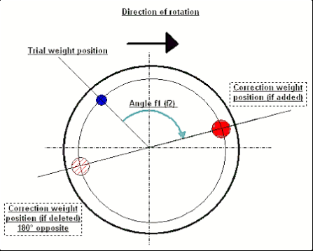
Fig. 7.11. కరెక్షన్ వెయిట్ మౌంటింగ్.
సిఫారసు చేయబడింది!
డైనమిక్ బ్యాలెన్సింగ్ చేయడానికి ముందు, స్టాటిక్ అసమతౌల్యత చాలా ఎక్కువగా లేదని నిర్ధారించుకోవడం సిఫార్సు చేయబడుతుంది. హారిజోంటల్ అక్షం ఉన్న రోటర్ల కోసం, రోటర్ను ప్రస్తుత స్థానం నుండి 90 డిగ్రీల కోణంలో మాన్యువల్గా తిప్పవచ్చు. రోటర్ స్టాటిక్గా అసమతౌల్యత కలిగి ఉంటే, అది సమతౌల్య స్థానానికి తిరుగుతుంది. రోటర్ సమతౌల్య స్థానాన్ని చేరుకున్న తర్వాత, రోటర్ పొడవు యొక్క మధ్య భాగంలో సుమారుగా పై బిందువులో బ్యాలెన్సింగ్ బరువును అమర్చాలి. ఏ స్థానంలోనూ రోటర్ కదలకుండా ఉండేలా బరువును ఎంపిక చేయాలి.
ఈ ప్రి-బ్యాలెన్సింగ్ బలంగా అసమతౌల్యత కలిగిన రోటర్ యొక్క మొదటి స్టార్ట్లో కంపన పరిమాణాన్ని తగ్గిస్తుంది.
సెన్సార్ అమరిక మరియు బిగింపు
Vకంపన సెన్సార్ ఎంపిక చేయబడిన కొలత బిందువులో మెషీన్పై ఇన్స్టాల్ చేయబడాలి మరియు USB ఇంటర్ఫేస్ యూనిట్ యొక్క ఇన్పుట్ X1 కి కనెక్ట్ చేయబడాలి.
రెండు మౌంటింగ్ కాన్ఫిగరేషన్లు ఉన్నాయి:
- మాగ్నెట్లు
- M4 దారపు స్టడ్లు
ఆప్టికల్ టాకో సెన్సార్ USB ఇంటర్ఫేస్ యూనిట్ యొక్క ఇన్పుట్ X3 కి కనెక్ట్ చేయబడాలి. అదనంగా, ఈ సెన్సార్ ఉపయోగం కోసం రోటర్ ఉపరితలంపై ప్రత్యేక ప్రతిబింబిత మార్క్ అప్లై చేయబడాలి.
📏 ఆప్టికల్ సెన్సార్ అమరిక అవసరాలు
- ✓రోటర్ ఉపరితలానికి దూరం: 50-500 mm (సెన్సార్ మోడల్ బట్టి)
- ✓రిఫ్లెక్టివ్ టేప్ వెడల్పు: కనీసం 1-1.5 సెం.మీ (వేగం మరియు వ్యాసార్థంపై ఆధారపడి)
- ✓ఓరియంటేషన్: రోటర్ ఉపరితలానికి లంబంగా
- ✓అమరిక: స్థిరమైన స్థానం కోసం మాగ్నెటిక్ స్టాండ్ లేదా క్లాంప్ ఉపయోగించండి
- ✓నేరుగా సూర్యకాంతి పడకుండా చూసుకోండి లేదా సెన్సార్/టేప్పై ప్రకాశవంతమైన కృత్రిమ వెలుతురు
💡 టేప్ వెడల్పు గణన: సరైన పనితీరు కోసం, కింది వాటిని ఉపయోగించి టేప్ వెడల్పును లెక్కించండి:
L ≥ (N × R)/30000 ≥ 1.0-1.5 cm
ఇక్కడ: L - టేప్ వెడల్పు (సెంమీ), N - రోటర్ వేగం (rpm), R - టేప్ వ్యాసార్థం (సెంమీ)
బ్యాలెన్సింగ్ సమయంలో సెన్సార్ల ఎంపిక మరియు వాటిని ఆబ్జెక్ట్కు అటాచ్ చేయడంపై వివరణాత్మక అవసరాలు అనుబంధ 1 లో ఉన్నాయి.
7.4 సింగిల్-ప్లేన్ బ్యాలెన్సింగ్
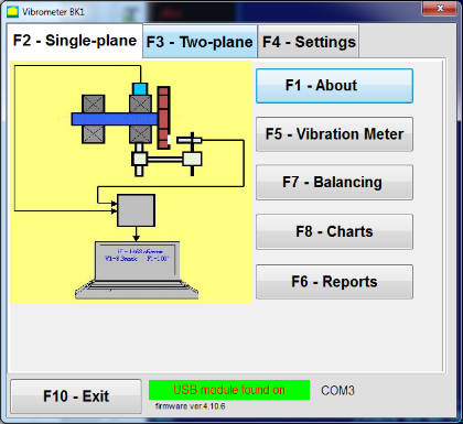
Fig. 7.12. "సింగిల్ ప్లేన్ బ్యాలెన్సింగ్"
బ్యాలెన్సింగ్ ఆర్కైవ్
"ఒకే-తల బ్యాలెన్సింగ్" మోడ్లో ప్రోగ్రామ్లో పని ప్రారంభించడానికి, "F2-ఒకే-తలం" బటన్ను క్లిక్ చేయండి (లేదా కంప్యూటర్ కీబోర్డ్లో F2 కీ నొక్కండి).
తర్వాత "F7 – బ్యాలెన్సింగ్" బటన్ను క్లిక్ చేయండి, తర్వాత ఒకే-తల బ్యాలెన్సింగ్ ఆర్కైవ్ విండో కనిపిస్తుంది, దీనిలో బ్యాలెన్సింగ్ డేటా సేవ్ చేయబడుతుంది (చిత్రం 7.13 చూడండి).

చిత్రం 7.13 సింగిల్ ప్లేన్లో బ్యాలెన్సింగ్ ఆర్కైవ్ ఎంపిక కోసం విండో.
ఈ విండోలో, మీరు రోటర్ యొక్క పేరుపై డేటాను ఎంటర్ చేయాలి (రోటర్ పేరు), రోటర్ ఇన్స్టాలేషన్ స్థానం (స్థానం), కంపనం మరియు శేష అసమతౌల్యత కోసం టాలరెన్సెస్ (టాలరెన్స్), కొలత తేదీ. ఈ డేటా డేటాబేస్లో నిల్వ చేయబడుతుంది. అలాగే, Arc### ఫోల్డర్ సృష్టించబడుతుంది, ఇక్కడ ### అనేది గ్రాఫ్లు, రిపోర్ట్ ఫైల్ మొదలైనవి సేవ్ చేయబడే ఆర్కైవ్ సంఖ్య. బ్యాలెన్సింగ్ పూర్తయిన తర్వాత, బిల్ట్-ఇన్ ఎడిటర్లో ఎడిట్ చేయబడే మరియు ప్రింట్ చేయబడే రిపోర్ట్ ఫైల్ జనరేట్ చేయబడుతుంది.
అవసరమైన డేటాను నమోదు చేసిన తర్వాత, మీరు “F10-OK" బటన్ను క్లిక్ చేయండి, తర్వాత "ఒకే-తల బ్యాలెన్సింగ్" విండో తెరుచుకుంటుంది (Fig. 7.13 చూడండి)
బ్యాలెన్సింగ్ సెట్టింగ్లు (1-తలం)
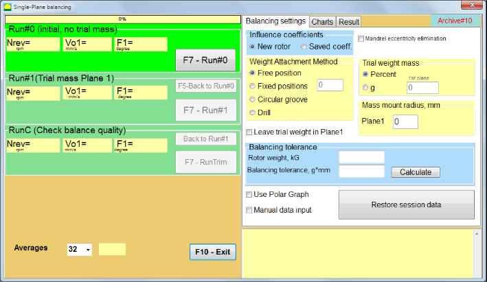
చిత్రం 7.14. సింగిల్ ప్లేన్. బ్యాలెన్సింగ్ సెట్టింగ్స్
ఈ విండో యొక్క ఎడమ వైపున వైబ్రేషన్ కొలత డేటా మరియు కొలత నియంత్రణ బటన్లు "Run # 0", "Run # 1", "RunTrim".
ఈ విండో యొక్క కుడి వైపున మూడు ట్యాబ్లు ఉన్నాయి:
- బ్యాలెన్సింగ్ సెట్టింగ్లు
- చార్ట్లు
- ఫలితం
"బ్యాలెన్సింగ్ సెట్టింగ్లు" ట్యాబ్ బ్యాలెన్సింగ్ సెట్టింగ్లను నమోదు చేయడానికి ఉపయోగిస్తారు:
- "ప్రభావ గుణకం" -
- "కొత్త రోటర్” – కొత్త రోటర్ యొక్క బ్యాలెన్సింగ్ను ఎంచుకోవడం, దీనికి నిల్వ చేయబడిన బ్యాలెన్సింగ్ గుణకాలు లేవు మరియు కరెక్షన్ వెయిట్ యొక్క ద్రవ్యరాశి మరియు ఇన్స్టాలేషన్ కోణాన్ని నిర్ణయించడానికి రెండు రన్లు అవసరం.
- "సేవ్ చేసిన గుణకాలు” – నిల్వ చేయబడిన బ్యాలెన్సింగ్ గుణకాలు ఉన్న రోటర్ను తిరిగి బ్యాలెన్స్ చేయడాన్ని ఎంచుకోవడం, దీనికి కరెక్షన్ వెయిట్ యొక్క భారం మరియు ఇన్స్టాలేషన్ కోణాన్ని నిర్ణయించడానికి ఒకే ఒక రన్ అవసరం.
- "ట్రయల్ వెయిట్ మాస్" -
- "శాతం" - దిద్దుబాటు బరువును పరీక్ష బరువు శాతంగా లెక్కిస్తారు.
- "గ్రాము" - పరీక్ష బరువు యొక్క తెలిసిన ద్రవ్యరాశి నమోదు చేయబడుతుంది మరియు దిద్దుబాటు బరువు యొక్క ద్రవ్యరాశి లెక్కించబడుతుంది గ్రాములు or in oz ఇంపీరియల్ విధానం కోసం.
⚠️ శ్రద్ధ వహించండి! "సేవ్ చేసిన గుణకాలు” మోడ్లో తదుపరి పని కోసం, ప్రారంభ బ్యాలెన్సింగ్ సమయంలో ట్రయల్ వెయిట్ ద్రవ్యరాశిని గ్రాములలో లేదా oz లలో నమోదు చేయాలి, % లో కాదు. స్కేల్స్ డెలివరీ ప్యాకేజీలో చేర్చబడ్డాయి.
- "బరువు అమర్చే పద్ధతి"
- "స్వేచ్ఛా స్థానం" - రోటర్ పరిధిపై ఏకపక్ష కోణ స్థానాల్లో బరువులు అమర్చవచ్చు.
- "స్థిర స్థానం” – రోటర్పై స్థిర కోణీయ స్థానాల్లో బరువును అమర్చవచ్చు, ఉదాహరణకు, బ్లేడ్లు లేదా రంధ్రాలపై (ఉదాహరణకు 12 రంధ్రాలు – 30 డిగ్రీలు) మొదలైనవి. తగిన ఫీల్డ్లో స్థిర స్థానాల సంఖ్యను నమోదు చేయాలి. బ్యాలెన్సింగ్ తర్వాత, ప్రోగ్రామ్ స్వయంచాలకంగా బరువును రెండు భాగాలుగా విభజించి, పొందిన ద్రవ్యరాశులను ఏర్పాటు చేయాల్సిన స్థానాల సంఖ్యను సూచిస్తుంది.
- "వృత్తాకార గాడి" – గ్రైండింగ్ వీల్ బ్యాలెన్సింగ్ కోసం ఉపయోగిస్తారు. ఈ సందర్భంలో అన్బ్యాలెన్స్ను తొలగించడానికి 3 కౌంటర్వెయిట్లు ఉపయోగిస్తారు
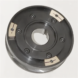
చిత్రం 7.17 3 కౌంటర్వెయిట్లతో గ్రైండింగ్ వీల్ బ్యాలెన్సింగ్
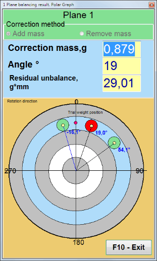
చిత్రం 7.18 గ్రైండింగ్ వీల్ బ్యాలెన్సింగ్. పోలార్ గ్రాఫ్.

చిత్రం 7.15. ఫలిత ట్యాబ్. కరెక్షన్ బరువు ఏర్పాటు యొక్క స్థిర స్థానం.
Z1 మరియు Z2 – అమర్చిన దిద్దుబాటు బరువుల స్థానాలు, భ్రమణ దిశ ప్రకారం Z1 స్థానం నుండి లెక్కించబడతాయి. Z1 అనేది పరీక్ష బరువు అమర్చిన స్థానం.
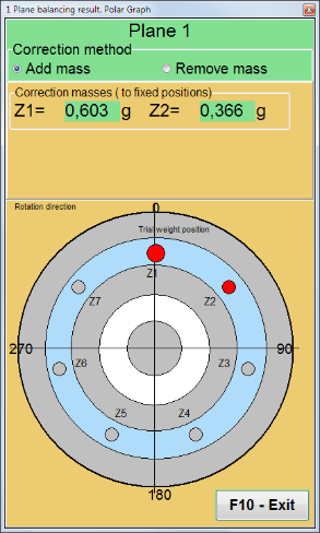
చిత్రం 7.16 ఫిక్స్డ్ పొజిషన్స్. పోలార్ డయాగ్రామ్.
- "ద్రవ్యరాశి అమరిక వ్యాసార్థం, mm" - "Plane1" - 1వ తలంలో పరీక్ష బరువు వ్యాసార్థం. బ్యాలెన్సింగ్ తర్వాత అవశేష అన్బ్యాలెన్స్ సహనాన్ని నిర్ణయించడానికి ప్రారంభ మరియు అవశేష అన్బ్యాలెన్స్ పరిమాణాన్ని లెక్కించడానికి ఇది అవసరం.
- "ట్రయల్ బరువును తలం1లో ఉంచండి.” సాధారణంగా బ్యాలెన్సింగ్ ప్రక్రియలో ట్రయల్ వెయిట్ తొలగించబడుతుంది. కానీ కొన్ని సందర్భాల్లో దానిని తొలగించడం సాధ్యం కాదు, అప్పుడు లెక్కల్లో ట్రయల్ వెయిట్ ద్రవ్యరాశిని పరిగణనలోకి తీసుకోవడానికి దీనిలో చెక్ మార్క్ పెట్టాలి.
- "మాన్యువల్ డేటా నమోదు” – విండో యొక్క ఎడమ వైపున ఉన్న తగిన ఫీల్డ్లలో వైబ్రేషన్ విలువ మరియు ఫేజ్ను మాన్యువల్గా నమోదు చేయడానికి మరియు కరెక్షన్ వెయిట్ యొక్క ద్రవ్యరాశి మరియు ఇన్స్టాలేషన్ కోణాన్ని లెక్కించడానికి ఉపయోగించబడుతుంది, “ఫలితాలు" ట్యాబ్
- బటన్ "సెషన్ డేటాను పునరుద్ధరించండి”. బ్యాలెన్సింగ్ సమయంలో, కొలిచిన డేటా session1.ini ఫైల్లో సేవ్ చేయబడుతుంది. కంప్యూటర్ ఫ్రీజింగ్ లేదా ఇతర కారణాల వల్ల కొలత ప్రక్రియ అంతరాయం కలిగితే, ఈ బటన్ను క్లిక్ చేయడం ద్వారా మీరు కొలత డేటాను పునరుద్ధరించి, అంతరాయం కలిగిన స్థానం నుండి బ్యాలెన్సింగ్ను కొనసాగించవచ్చు.
- మాండ్రెల్ ఎక్సెంట్రిసిటీ తొలగింపు (ఇండెక్స్ బ్యాలెన్సింగ్) మండ్రెల్ (బ్యాలెన్సింగ్ ఆర్బర్) యొక్క ఉత్కేంద్రత ప్రభావాన్ని తొలగించడానికి అదనపు స్టార్ట్తో బ్యాలెన్సింగ్. రోటర్ను 0° మరియు 180° కోణాల్లో ప్రత్యామ్నాయంగా ఏర్పాటు చేయండి. రెండు స్థానాల్లోనూ అసమతౌల్యాలను కొలవండి.
- బ్యాలెన్సింగ్ టాలరెన్స్ g x mm (G-క్లాసులు) లో మిగిలిన అసమతౌల్య టాలరెన్స్లను నమోదు చేయడం లేదా లెక్కించడం
- పోలార్ గ్రాఫ్ ఉపయోగించండి బ్యాలెన్సింగ్ ఫలితాలను ప్రదర్శించడానికి పోలార్ గ్రాఫ్ ఉపయోగించండి
1-ప్లేన్ బ్యాలెన్సింగ్. కొత్త రోటర్
పైన పేర్కొన్నట్లుగా, "కొత్త రోటర్" బ్యాలెన్సింగ్కు రెండు పరీక్ష రన్లు మరియు బ్యాలెన్సింగ్ మెషీన్ యొక్క కనీసం ఒక ట్రిమ్ రన్ అవసరం.
రన్#0 (ప్రారంభ రన్)
బ్యాలెన్సింగ్ రోటర్పై సెన్సార్లను అమర్చి, సెట్టింగ్ పారామితులను నమోదు చేసిన తర్వాత, రోటర్ భ్రమణాన్ని ఆన్ చేసి, అది పనిచేసే వేగాన్ని చేరుకున్నప్పుడు “Run#0" కొలతలు ప్రారంభించడానికి బటన్. "చార్ట్లు" ట్యాబ్ కుడి ప్యానెల్లో తెరుచుకుంటుంది, అక్కడ వైబ్రేషన్ యొక్క వేవ్ ఫారమ్ మరియు స్పెక్ట్రమ్ చూపబడతాయి. ట్యాబ్ దిగువ భాగంలో, సమయ సూచనతో అన్ని స్టార్ట్ల ఫలితాలు నిల్వ చేయబడే హిస్టరీ ఫైల్ ఉంటుంది. డిస్క్లో, ఈ ఫైల్ ఆర్కైవ్ ఫోల్డర్లో memo.txt అనే పేరుతో సేవ్ చేయబడుతుంది
గమనిక!
కొలతను ప్రారంభించే ముందు, బ్యాలెన్సింగ్ మెషీన్ యొక్క రోటర్ భ్రమణాన్ని ఆన్ చేయాలి (Run#0) మరియు రోటర్ వేగం స్థిరంగా ఉందని నిర్ధారించుకోండి.
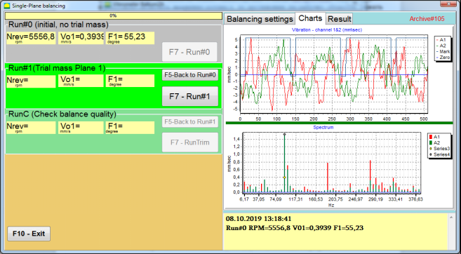
చిత్రం 7.19. ఒక తలంలో బ్యాలెన్సింగ్. ప్రారంభ రన్ (Run#0). చార్ట్స్ ట్యాబ్
కొలత ప్రక్రియ పూర్తయిన తర్వాత, Run#0 విభాగంలో, ఎడమ ప్యానెల్లో కొలత ఫలితాలు కనిపిస్తాయి – రోటర్ వేగం (RPM), 1x వైబ్రేషన్ యొక్క RMS (Vo1) మరియు ఫేజ్ (F1).
"F5-రన్#0కి తిరిగి” బటన్ (లేదా F5 ఫంక్షన్ కీ) Run#0 విభాగానికి తిరిగి వెళ్లడానికి మరియు అవసరమైతే వైబ్రేషన్ పారామితులను మళ్లీ కొలవడానికి ఉపయోగించబడుతుంది.
రన్#1 (ట్రయల్ ద్రవ్యరాశి తలం 1)
"రన్#1 (ట్రయల్ ద్రవ్యరాశి తలం 1), ట్రయల్ వెయిట్ను అమర్చాలి "ట్రయల్ బరువు ద్రవ్యరాశి" ఫీల్డ్.
ట్రయల్ బరువును ఏర్పాటు చేయడం యొక్క లక్ష్యం, తెలిసిన స్థానంలో (కోణం) తెలిసిన బరువును ఏర్పాటు చేసినప్పుడు రోటర్ కంపనం ఎలా మారుతుందో అంచనా వేయడం. ట్రయల్ బరువు ప్రారంభ యాంప్లిట్యూడ్ కంటే 30% తక్కువ లేదా ఎక్కువగా కంపన యాంప్లిట్యూడ్ను మార్చాలి లేదా ప్రారంభ ఫేజ్ కంటే 30 డిగ్రీలు లేదా అంతకంటే ఎక్కువ ఫేజ్ను మార్చాలి.
"సేవ్ చేసిన గుణకాలు” బ్యాలెన్సింగ్లో తదుపరి పని కోసం, ట్రయల్ వెయిట్ యొక్క ఇన్స్టాలేషన్ స్థానం (కోణం) రిఫ్లెక్టివ్ మార్క్ యొక్క స్థానం (కోణం)తో సమానంగా ఉండాలి.
బ్యాలెన్సింగ్ మెషీన్ యొక్క రోటర్ భ్రమణాన్ని మళ్లీ ఆన్ చేసి, దాని భ్రమణ ఫ్రీక్వెన్సీ స్థిరంగా ఉందని నిర్ధారించుకోండి. తర్వాత “F7-Run#1" బటన్ను క్లిక్ చేయండి (లేదా కంప్యూటర్ కీబోర్డ్లో F7 కీ నొక్కండి).
కొలత తర్వాత "రన్#1 (ట్రయల్ ద్రవ్యరాశి తలం 1)" విభాగంలో సంబంధిత విండోలలో, రోటర్ వేగం (RPM) కొలత ఫలితాలు, అలాగే 1x వైబ్రేషన్ యొక్క RMS భాగం (Vо1) మరియు ఫేజ్ (F1) విలువ కనిపిస్తాయి.
అదే సమయంలో, "ఫలితం" ట్యాబ్ విండో కుడి వైపున తెరుచుకుంటుంది.
ఈ ట్యాబ్ అసమతౌల్యాన్ని పరిహరించడానికి రోటర్పై ఏర్పాటు చేయవలసిన సవరణ బరువు యొక్క ద్రవ్యరాశి మరియు కోణాన్ని లెక్కించడం యొక్క ఫలితాలను ప్రదర్శిస్తుంది.
అంతేకాకుండా, పోలార్ కోఆర్డినేట్ సిస్టమ్ను ఉపయోగించే సందర్భంలో, డిస్ప్లే కరెక్షన్ బరువు యొక్క ద్రవ్యరాశి విలువను (M1) మరియు ఏర్పాటు కోణాన్ని (f1) చూపిస్తుంది.
"స్థిర స్థానాలు” స్థానాల సంఖ్యలు (Zi, Zj) మరియు విభజించిన ట్రయల్ వెయిట్ ద్రవ్యరాశి చూపబడతాయి.
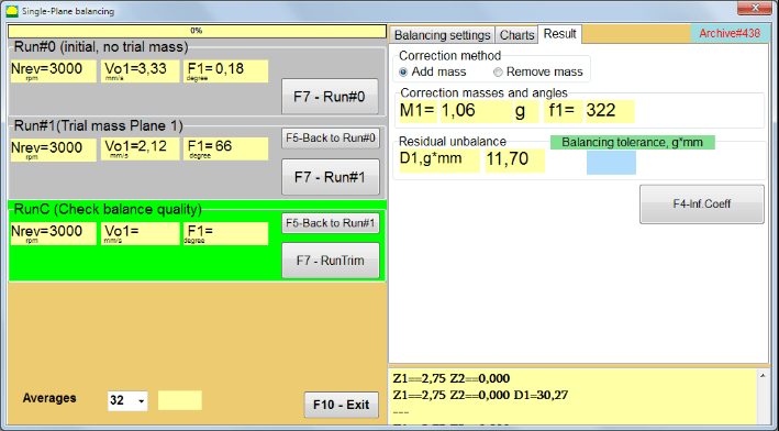
చిత్రం 7.20. ఒక తలంలో బ్యాలెన్సింగ్. Run#1 మరియు బ్యాలెన్సింగ్ ఫలితం.
If పోలార్ గ్రాఫ్ తనిఖీ చేయబడితే, పోలార్ డయాగ్రామ్ చూపబడుతుంది.
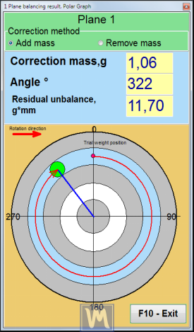
చిత్రం 7.21. బ్యాలెన్సింగ్ ఫలితం. పోలార్ గ్రాఫ్.
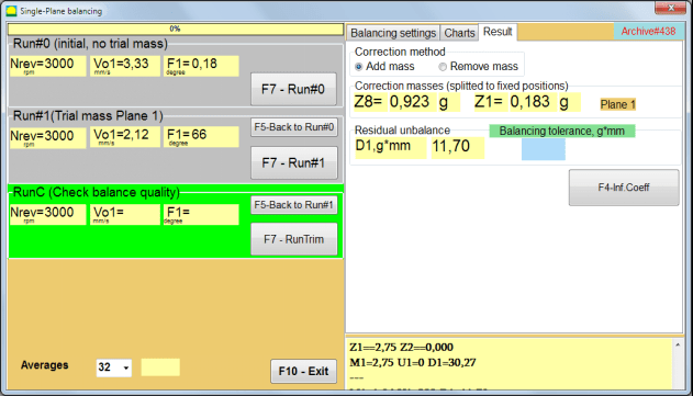
చిత్రం 7.22. బ్యాలెన్సింగ్ ఫలితం. బరువు విభజించబడింది (స్థిర స్థానాలు)
అలాగే ఒకవేళ "పోలార్ గ్రాఫ్" తనిఖీ చేయబడింది, Polar graph చూపబడుతుంది.
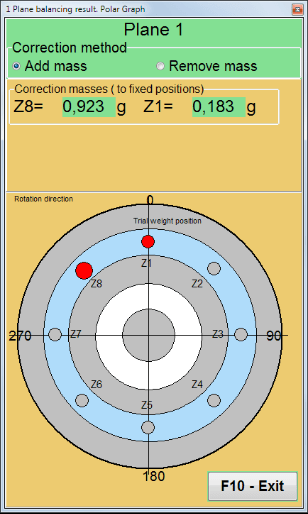
చిత్రం 7.23. స్థిరమైన స్థానాలలో విభజించబడిన బరువు. ధ్రువ రేఖాచిత్రం
⚠️ శ్రద్ధ వహించండి!
- 1. బ్యాలెన్సింగ్ మెషీన్ యొక్క రెండవ రన్ వద్ద (“రన్#1 (ట్రయల్ ద్రవ్యరాశి తలం 1)”) కొలత ప్రక్రియను పూర్తి చేసిన తర్వాత, భ్రమణాన్ని ఆపి, అమర్చిన ట్రయల్ వెయిట్ను తొలగించడం అవసరం. తర్వాత రిజల్ట్ ట్యాబ్ డేటా ప్రకారం రోటర్పై కరెక్షన్ వెయిట్ను అమర్చండి (లేదా తొలగించండి).
ట్రయల్ వెయిట్ తొలగించకపోతే, మీరు “బ్యాలెన్సింగ్ సెట్టింగ్లు" ట్యాబ్ మరియు "ట్రయల్ బరువును తలం1లో ఉంచండి". ఆపై "ఫలితం” ట్యాబ్కు మారండి. కరెక్షన్ వెయిట్ యొక్క బరువు మరియు ఇన్స్టాలేషన్ కోణం స్వయంచాలకంగా తిరిగి లెక్కించబడతాయి.
- సరిదిద్దే వెయిట్ యొక్క కోణ స్థానం trial weight అమర్చిన స్థానం నుండి నిర్ణయించబడుతుంది. కోణం యొక్క సూచన దిశ రోటర్ తిరిగే దిశతో సమానంగా ఉంటుంది.
- "స్థిర స్థానం" - 1st స్థానం (Z1), ట్రయల్ బరువు ఏర్పాటు చేయబడిన స్థానంతో సరిపోలుతుంది. స్థానం సంఖ్య యొక్క లెక్కింపు దిశ రోటర్ యొక్క భ్రమణ దిశలో ఉంటుంది.
- 4. డిఫాల్ట్గా కరెక్షన్ వెయిట్ రోటర్కు జోడించబడుతుంది. దీనిని “జోడించు" ఫీల్డ్. బరువును తొలగిస్తున్నప్పుడు (ఉదాహరణకు, డ్రిల్లింగ్ ద్వారా), మీరు "తొలగించు” ఫీల్డ్లో గుర్తు పెట్టాలి, దాని తర్వాత కరెక్షన్ వెయిట్ యొక్క కోణీయ స్థానం స్వయంచాలకంగా 180º మారుతుంది.
ఆపరేటింగ్ విండోలో బ్యాలెన్సింగ్ రోటర్పై కరెక్షన్ వెయిట్ను అమర్చిన తర్వాత, RunC (ట్రిమ్) నిర్వహించి, చేసిన బ్యాలెన్సింగ్ యొక్క ప్రభావాన్ని మూల్యాంకనం చేయడం అవసరం.
రన్C (బ్యాలెన్స్ నాణ్యత తనిఖీ)
⚠️ శ్రద్ధ వహించండి! దీనిపై కొలత ప్రారంభించే ముందు RunC, యంత్రం యొక్క రోటర్ భ్రమణాన్ని ఆన్ చేసి, అది ఆపరేటింగ్ మోడ్లోకి ప్రవేశించిందని (స్థిరమైన భ్రమణ పౌనఃపున్యం) నిర్ధారించుకోవాలి.
"రన్C (బ్యాలెన్స్ నాణ్యత తనిఖీ)" విభాగంలో vibration కొలత చేయడానికి, "F7 – RunTrim" బటన్ క్లిక్ చేయండి (లేదా keyboard లో F7 కీ నొక్కండి).
కొలత ప్రక్రియ విజయవంతంగా పూర్తయిన తర్వాత, "రన్C (బ్యాలెన్స్ నాణ్యత తనిఖీ)" విభాగంలో ఎడమ panel లో, రోటర్ వేగం (RPM) యొక్క కొలత ఫలితాలు, అలాగే 1x vibration యొక్క RMS భాగం (Vo1) మరియు phase (F1) విలువలు కనిపిస్తాయి.
"ఫలితం” ట్యాబ్లో, అదనపు కరెక్షన్ వెయిట్ యొక్క ద్రవ్యరాశి మరియు ఇన్స్టాలేషన్ కోణం లెక్కింపు ఫలితాలు ప్రదర్శించబడతాయి.
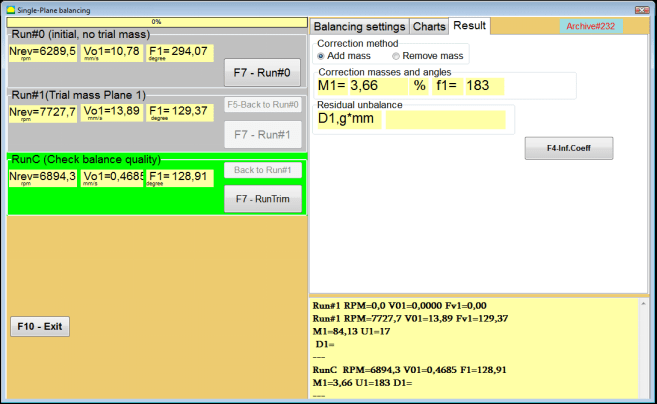
చిత్రం 7.24. ఒక ప్లేన్లో బ్యాలెన్సింగ్. RunTrim నిర్వహించడం. ఫలితాల ట్యాబ్
ఈ బరువును ఇప్పటికే రోటర్పై మౌంట్ చేయబడిన కరెక్షన్ బరువుకు జోడించవచ్చు, మిగిలి ఉన్న అసమతౌల్యాన్ని పరిహరించడానికి. అదనంగా, బ్యాలెన్సింగ్ తర్వాత సాధించిన మిగిలి ఉన్న రోటర్ అసమతౌల్యం ఈ విండో యొక్క దిగువ భాగంలో ప్రదర్శించబడుతుంది.
మిగిలి ఉన్న కంపనం మరియు / లేదా బ్యాలెన్స్ చేయబడిన రోటర్ యొక్క మిగిలి ఉన్న అసమతౌల్యం పరిమాణం సాంకేతిక పత్రాలలో స్థాపించబడిన టాలరెన్స్ అవసరాలను పాటిస్తే, బ్యాలెన్సింగ్ ప్రక్రియను పూర్తి చేయవచ్చు.
ఇతర విధంగా, బ్యాలెన్సింగ్ ప్రక్రియ కొనసాగవచ్చు. ఇది బ్యాలెన్స్ చేయబడిన రోటర్పై కరెక్షన్ బరువును ఇన్స్టాల్ (తొలగించడం) చేసేటప్పుడు సంభవించే సాధ్యమయ్యే లోపాలను సరిచేయడానికి క్రమబద్ధమైన సమీపనల పద్ధతిని అనుమతిస్తుంది.
బ్యాలెన్సింగ్ రోటర్పై బ్యాలెన్సింగ్ ప్రక్రియను కొనసాగిస్తున్నప్పుడు, అదనపు కరెక్షన్ ద్రవ్యరాశిని అమర్చడం (తొలగించడం) అవసరం, దీని పారామితులు “కరెక్షన్ మాస్లు మరియు కోణాలు".
ప్రభావ గుణకాలు (1-తలం)
"F4-ప్రభావ గుణ." బటన్లో ఉన్న "ఫలితం" ట్యాబ్ calibration రన్ ల ఫలితాల నుండి లెక్కించిన రోటర్ balancing coefficients (Influence coefficients) ను కంప్యూటర్ మెమరీలో చూడడానికి మరియు నిల్వ చేయడానికి ఉపయోగిస్తారు.
అది నొక్కినప్పుడు, "ప్రభావ గుణకాలు (ఒకే తలం)" విండో కంప్యూటర్ display లో కనిపిస్తుంది, దానిలో calibration (test) రన్ ల ఫలితాల నుండి లెక్కించిన balancing coefficients చూపబడతాయి. ఈ యంత్రం యొక్క తదుపరి balancing లో "సేవ్ చేసిన గుణకాలు” మోడ్లో, ఈ గుణకాలు కంప్యూటర్ మెమరీలో నిల్వ చేయబడాలి.
దీన్ని చేయడానికి, "F9 - సేవ్" బటన్ను క్లిక్ చేసి, ఆర్కైవ్ యొక్క రెండవ పేజీకి వెళ్ళండి: "ప్రభావ గుణకం ఆర్కైవ్. సింగిల్ ప్లేన్."

చిత్రం 7.25. 1వ ప్లేన్లో బ్యాలెన్సింగ్ గుణకాలు
తర్వాత మీరు ఈ యంత్రం పేరును “రోటర్" కాలమ్లో నమోదు చేసి, "F2-సేవ్” బటన్ను క్లిక్ చేసి కంప్యూటర్లో పేర్కొన్న డేటాను సేవ్ చేయండి.
తర్వాత “F10-నిష్క్రమించు" బటన్ను (లేదా కంప్యూటర్ కీబోర్డ్లోని F10 ఫంక్షన్ కీని) నొక్కడం ద్వారా మీరు మునుపటి విండోకు తిరిగి వెళ్ళవచ్చు.
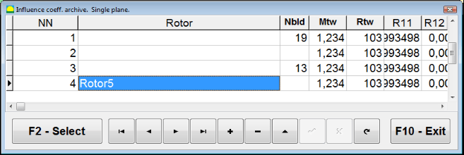
చిత్రం 7.26. "ప్రభావ గుణకం ఆర్కైవ్. సింగిల్ ప్లేన్."
బ్యాలెన్సింగ్ నివేదిక
బ్యాలెన్సింగ్ తర్వాత అన్ని డేటా సేవ్ చేయబడి బ్యాలెన్సింగ్ నివేదిక సృష్టించబడుతుంది. మీరు బిల్ట్-ఇన్ ఎడిటర్లో నివేదికను వీక్షించి సవరించవచ్చు. "ఒక plane లో Balancing archive" (చిత్రం 7.9) బటన్ నొక్కండి "F9 -రిపోర్ట్" balancing నివేదిక editor కి వెళ్ళడానికి.
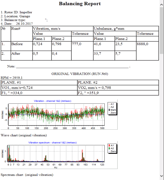
Fig. 7.27. Balancing నివేదిక.
Saved coeff. 1 ప్లేన్లో సేవ్ చేసిన ఇన్ఫ్లుయెన్స్ కోఎఫిషియెంట్లతో బ్యాలెన్సింగ్ విధానం
కొలత వ్యవస్థను సెటప్ చేయడం (ప్రారంభ డేటా ఇన్పుట్)
సేవ్ చేసిన గుణకాలతో బ్యాలెన్సింగ్ బ్యాలెన్సింగ్ గుణకాలు ఇప్పటికే నిర్ణయించబడి మరియు కంప్యూటర్ మెమరీలో ఎంటర్ చేయబడిన యంత్రంపై నిర్వహించబడవచ్చు.
⚠️ శ్రద్ధ వహించండి! సేవ్ చేయబడిన గుణకాలతో బ్యాలెన్సింగ్ చేసేటప్పుడు, కంపన సెన్సార్ మరియు ఫేజ్ కోణ సెన్సార్ ప్రారంభ బ్యాలెన్సింగ్ సమయంలో ఉన్నట్లుగానే ఇన్స్టాల్ చేయబడాలి.
కోసం ప్రారంభ డేటా ఇన్పుట్ సేవ్ చేసిన గుణకాలతో బ్యాలెన్సింగ్ (ప్రాథమిక("కొత్త రోటర్") balancing విషయంలో వలె) "సింగిల్ ప్లేన్ బ్యాలెన్సింగ్. బ్యాలెన్సింగ్ సెట్టింగ్స్.".
ఈ సందర్భంలో, "ప్రభావ గుణకాలు" విభాగంలో, "సేవ్ చేసిన గుణకాలు" అంశం ఎంచుకోండి. ఈ సందర్భంలో, "" యొక్క రెండవ పేజీప్రభావ గుణకాల ఆర్కైవ్. ఒకే తలం.", ఇది నిల్వ చేయబడిన balancing coefficients యొక్క archive ను కలిగి ఉంటుంది.
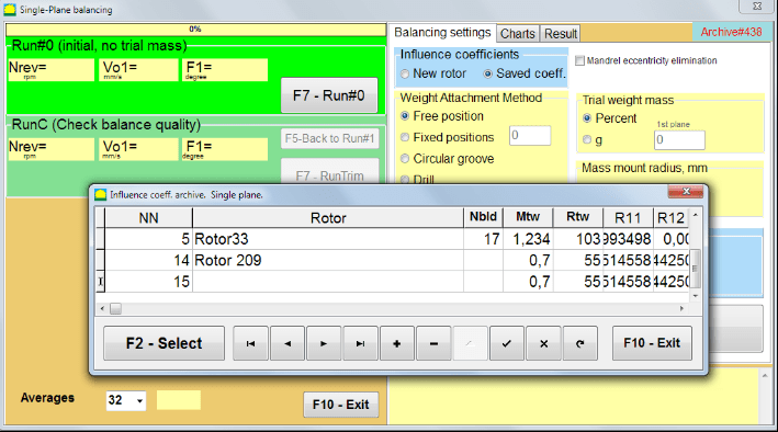
చిత్రం 7.28. 1 ప్లేన్లో సేవ్ చేయబడిన ప్రభావ గుణకాలతో బ్యాలెన్సింగ్
"►" లేదా "◄" control బటన్లను ఉపయోగించి ఈ archive యొక్క table ద్వారా కదులుతూ, మనకు అవసరమైన యంత్రం యొక్క balancing coefficients తో కావలసిన record ను ఎంచుకోవచ్చు. ఆపై, ప్రస్తుత కొలతలలో ఈ డేటాను ఉపయోగించడానికి, "F2 – ఎంచుకోండి" బటన్.
ఆ తర్వాత “సింగిల్ ప్లేన్ బ్యాలెన్సింగ్. బ్యాలెన్సింగ్ సెట్టింగ్స్." స్వయంచాలకంగా నింపబడతాయి.
ప్రాథమిక డేటా ఇన్పుట్ పూర్తి చేసిన తర్వాత, మీరు కొలతలను ప్రారంభించవచ్చు.
నిల్వ చేయబడిన influence coefficients తో balancing సమయంలో కొలతలు
సేవ్ చేయబడిన ప్రభావ గుణకాలతో బ్యాలెన్సింగ్ కేవలం ఒక ప్రారంభ రన్ మరియు కనీసం ఒక టెస్ట్ రన్ను అవసరం చేస్తుంది.
⚠️ శ్రద్ధ వహించండి! కొలతను ప్రారంభించే ముందు, రోటర్ భ్రమణాన్ని ఆన్ చేసి, భ్రమణ పౌనఃపున్యం స్థిరంగా ఉందని నిర్ధారించుకోవాలి.
"రన్#0 (ప్రారంభ, ట్రయల్ ద్రవ్యరాశి లేకుండా)" విభాగంలో, నొక్కండి "F7 – Run#0" (లేదా కంప్యూటర్ keyboard లో F7 కీ నొక్కండి).
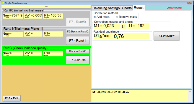
చిత్రం 7.29. ఒక ప్లేన్లో సేవ్ చేయబడిన ప్రభావ గుణకాలతో బ్యాలెన్సింగ్. ఒక రన్ తర్వాత ఫలితాలు.
"" యొక్క సంబంధిత ఫీల్డ్ లలోRun#0" విభాగంలో, రోటర్ వేగం (RPM) కొలత ఫలితాలు, 1x vibration యొక్క RMS భాగం (Vо1) మరియు phase (F1) విలువలు కనిపిస్తాయి.
అదే సమయంలో, "ఫలితం” ట్యాబ్ కరెక్షన్ వెయిట్ యొక్క ద్రవ్యరాశి మరియు కోణం లెక్కింపు ఫలితాలను ప్రదర్శిస్తుంది, ఇది అసమతుల్యతను భర్తీ చేయడానికి రోటర్పై అమర్చాలి.
అంతేకాక, polar coordinate system ఉపయోగించిన సందర్భంలో, display లో correction weights యొక్క mass విలువలు మరియు అమర్చే కోణాలు చూపబడతాయి.
కరెక్షన్ బరువును స్థిరమైన స్థానాలలో విభజించే సందర్భంలో, బ్యాలెన్సింగ్ రోటర్ యొక్క స్థానాల సంఖ్య మరియు వాటిపై ఇన్స్టాల్ చేయవలసిన బరువు యొక్క ద్రవ్యరాశి ప్రదర్శించబడతాయి.
ఇంకా, ప్రాథమిక బ్యాలెన్సింగ్ కోసం 7.4.2 విభాగంలో పేర్కొన్న సిఫార్సుల ప్రకారం బ్యాలెన్సింగ్ ప్రక్రియ నిర్వహించబడుతుంది.
మాండ్రెల్ ఎక్సెంట్రిసిటీ తొలగింపు (ఇండెక్స్ బ్యాలెన్సింగ్)
బ్యాలెన్సింగ్ సమయంలో రోటర్ను సిలిండరికల్ మాండ్రెల్లో స్థాపించినట్లయితే, మాండ్రెల్ యొక్క ఎక్సెంట్రిసిటీ అదనపు దోషాన్ని ప్రవేశపెట్టవచ్చు. ఈ దోషాన్ని తొలగించడానికి, రోటర్ను మాండ్రెల్లో 180 డిగ్రీలు తిప్పి అదనపు స్టార్ట్ చేయాలి. దీనిని ఇండెక్స్ బ్యాలెన్సింగ్ అంటారు.
ఇండెక్స్ బ్యాలెన్సింగ్ నిర్వహించడానికి, Balanset-1A ప్రోగ్రామ్లో ఒక ప్రత్యేక ఆప్షన్ అందుబాటులో ఉంది. మాండ్రెల్ ఎక్సెంట్రిసిటీ ఎలిమినేషన్ ఛెక్ చేసినప్పుడు, బ్యాలెన్సింగ్ విండోలో అదనపు RunEcc సెక్షన్ కనిపిస్తుంది.

చిత్రం 7.30. ఇండెక్స్ బ్యాలెన్సింగ్ కోసం పని విండో.
Run # 1 (Trial mass Plane 1) నడుపిన తర్వాత, ఒక విండో కనిపిస్తుంది
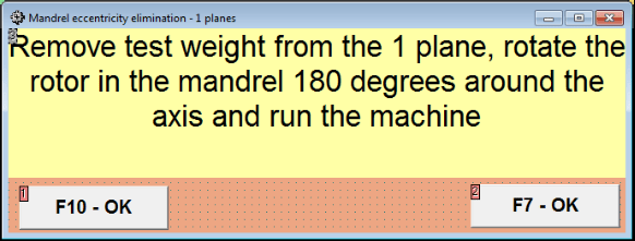
చిత్రం 7.31 ఇండెక్స్ బ్యాలెన్సింగ్ అవగాహన విండో.
రోటర్ను 180° తిప్పి అమర్చిన తర్వాత, Run Ecc పూర్తి చేయాలి. మాండ్రెల్ ఎక్సెంట్రిసిటీని ప్రభావితం చేయకుండా ప్రోగ్రామ్ నిజమైన రోటర్ అసమతుల్యతను స్వయంచాలకంగా లెక్కిస్తుంది.
7.5 రెండు plane balancing
లో పని ప్రారంభించే ముందు రెండు-తలాల బ్యాలెన్సింగ్ మోడ్లో, ఎంచుకున్న కొలత బిందువుల వద్ద యంత్ర శరీరంపై వైబ్రేషన్ సెన్సార్లను స్థాపించి, వాటిని కొలత యూనిట్ యొక్క X1 మరియు X2 ఇన్పుట్లకు వరుసగా కనెక్ట్ చేయాలి.
ఒక ఆప్టికల్ ఫేజ్ యాంగిల్ సెన్సార్ను కొలత యూనిట్ యొక్క X3 ఇన్పుట్కు కనెక్ట్ చేయాలి. అదనంగా, ఈ సెన్సార్ను ఉపయోగించడానికి, బ్యాలెన్సింగ్ యంత్రం యొక్క అందుబాటులో ఉన్న రోటర్ ఉపరితలంపై రిఫ్లెక్టివ్ టేప్ను అంటించాలి.
బ్యాలెన్సింగ్ సమయంలో సెన్సార్ల స్థాపన స్థానాన్ని ఎంచుకోవడం మరియు వాటిని సదుపాయంలో మౌంట్ చేయడం కోసం వివరణాత్మక అవసరాలను అపెండిక్స్ 1లో పేర్కొన్నారు.
"రెండు-తలాల బ్యాలెన్సింగ్" mode లో program పని ప్రోగ్రాముల Main window నుండి మొదలవుతుంది.
"" బటన్ క్లిక్ చేయండిF3-రెండు తలాలు" బటన్ (లేదా కంప్యూటర్ keyboard లో F3 కీ నొక్కండి).
తర్వాత, “F7 – Balancing” బటన్ను క్లిక్ చేయండి, దాని తర్వాత కంప్యూటర్ డిస్ప్లేపై ఒక వర్కింగ్ విండో కనిపిస్తుంది (చిత్రం 7.13 చూడండి), ఇందులో రెండు ప్లేన్లలో బ్యాలెన్సింగ్ చేసేటప్పుడు డేటాను సేవ్ చేయడానికి ఆర్కైవ్ను ఎంపిక చేసుకోవచ్చు.
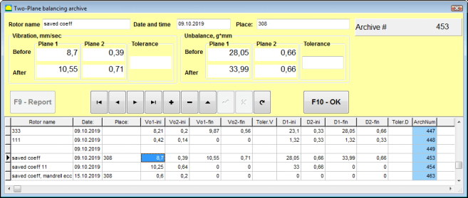
చిత్రం 7.32 టూ ప్లేన్ బ్యాలెన్సింగ్ ఆర్కైవ్ విండో.
ఈ విండోలో మీరు బ్యాలెన్స్ చేయబడే రోటర్ డేటాను నమోదు చేయాలి. “F10-OK" బటన్, బ్యాలెన్సింగ్ విండో కనిపిస్తుంది.
బ్యాలెన్సింగ్ సెట్టింగ్లు (2-తలాలు)
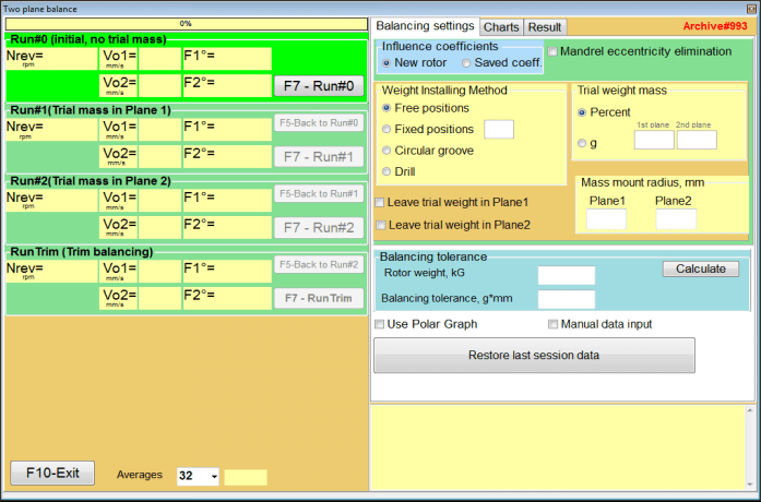
చిత్రం 7.33. రెండు తలాలలో బ్యాలెన్సింగ్ విండో.
విండో యొక్క కుడి వైపున "బ్యాలెన్సింగ్ సెట్టింగ్లు" బ్యాలెన్సింగ్ చేయడానికి ముందు సెట్టింగ్లను నమోదు చేయడానికి ట్యాబ్.
- ప్రభావ గుణకాలు – కొత్త రోటర్ను బ్యాలెన్స్ చేయడం లేదా నిల్వ చేసిన ఇన్ఫ్లుయెన్స్ కోఎఫిషియెంట్లను (బ్యాలెన్సింగ్ గుణకాలు) ఉపయోగించి బ్యాలెన్స్ చేయడం
- మాండ్రెల్ ఎక్సెంట్రిసిటీ తొలగింపు - మాండ్రెల్ యొక్క ఎక్సెంట్రిసిటీ ప్రభావాన్ని తొలగించేందుకు అదనపు స్టార్ట్తో బ్యాలెన్సింగ్
- బరువు అమర్చే పద్ధతి – రోటర్ చుట్టుకొలతపై ఏకపక్ష స్థానంలో లేదా స్థిర స్థానంలో కరెక్షన్ వెయిట్లను అమర్చడం. ద్రవ్యరాశిని తొలగించేటప్పుడు డ్రిల్లింగ్ కోసం లెక్కలు.
- "స్వేచ్ఛా స్థానం" - రోటర్ పరిధిపై ఏకపక్ష కోణ స్థానాల్లో బరువులు అమర్చవచ్చు.
- "స్థిర స్థానం” – రోటర్పై స్థిర కోణీయ స్థానాల్లో బరువును అమర్చవచ్చు, ఉదాహరణకు, బ్లేడ్లు లేదా రంధ్రాలపై (ఉదాహరణకు 12 రంధ్రాలు – 30 డిగ్రీలు) మొదలైనవి. తగిన ఫీల్డ్లో స్థిర స్థానాల సంఖ్యను నమోదు చేయాలి. బ్యాలెన్సింగ్ తర్వాత, ప్రోగ్రామ్ స్వయంచాలకంగా బరువును రెండు భాగాలుగా విభజించి, పొందిన ద్రవ్యరాశులను ఏర్పాటు చేయాల్సిన స్థానాల సంఖ్యను సూచిస్తుంది.
- ట్రయల్ బరువు ద్రవ్యరాశి - ట్రయల్ వెయిట్
- ట్రయల్ బరువును తలం1 / తలం2లో ఉంచండి - బ్యాలెన్సింగ్ సమయంలో ట్రయల్ వెయిట్ను తొలగించాలా లేదా ఉంచాలా.
- ద్రవ్యరాశి అమరిక వ్యాసార్థం, mm - ట్రయల్ మరియు కరెక్టివ్ వెయిట్లను అమర్చే వ్యాసార్థం
- బ్యాలెన్సింగ్ టాలరెన్స్ - g-mm లో రెసిడ్యువల్ అన్బ్యాలెన్స్ టాలరెన్స్లను నమోదు చేయడం లేదా లెక్కించడం
- పోలార్ గ్రాఫ్ ఉపయోగించండి - బ్యాలెన్సింగ్ ఫలితాలను ప్రదర్శించడానికి పోలార్ గ్రాఫ్ ఉపయోగించడం
- మాన్యువల్ డేటా నమోదు - బ్యాలెన్సింగ్ వెయిట్లను లెక్కించడానికి మాన్యువల్ డేటా నమోదు
- చివరి సెషన్ డేటాను పునరుద్ధరించండి - బ్యాలెన్సింగ్ కొనసాగించడానికి వైఫల్యం సంభవించినప్పుడు చివరి సెషన్ యొక్క కొలత డేటాను రికవరీ చేయడం.
2 ప్లేన్లలో బ్యాలెన్సింగ్. కొత్త రోటర్
కొలత వ్యవస్థను సెటప్ చేయడం (ప్రారంభ డేటా ఇన్పుట్)
కోసం ప్రారంభ డేటా ఇన్పుట్ కొత్త రోటర్ బ్యాలెన్సింగ్ "రెండు-ప్లేన్ బ్యాలెన్సింగ్. సెట్టింగ్స్".
ఈ సందర్భంలో, "ప్రభావ గుణకాలు" విభాగంలో, "కొత్త రోటర్" అంశం.
తదుపరి, "ట్రయల్ బరువు ద్రవ్యరాశి" విభాగంలో, ట్రయల్ వెయిట్ యొక్క ద్రవ్యరాశి కొలత యూనిట్ను ఎంచుకోవాలి - "గ్రాము" లేదా "శాతం".
కొలత యూనిట్ "శాతం”, తదుపరి అన్ని కరెక్షన్ వెయిట్ ద్రవ్యరాశి లెక్కలు ట్రయల్ వెయిట్ ద్రవ్యరాశికి సంబంధించి శాతంగా చేయబడతాయి.
"గ్రాము” కొలత యూనిట్గా ఉంటే, తదుపరి అన్ని కరెక్షన్ వెయిట్ ద్రవ్యరాశి లెక్కలు గ్రాములలో చేయబడతాయి. తర్వాత “గ్రాము" రోటర్పై అమర్చబడే ట్రయల్ వెయిట్ల ద్రవ్యరాశి.
⚠️ శ్రద్ధ వహించండి! "సేవ్ చేసిన గుణకాలు” మోడ్లో తదుపరి పని కోసం, ప్రారంభ బ్యాలెన్సింగ్ సమయంలో ట్రయల్ వెయిట్ల ద్రవ్యరాశిని నమోదు చేయాలి గ్రాములు.
తర్వాత ఎంచుకోండి "బరువు అమర్చే పద్ధతి" - "చుట్టుకొలత" లేదా "స్థిర స్థానం".
మీరు "స్థిర స్థానం" ఎంచుకుంటే, స్థానాల సంఖ్యను నమోదు చేయాలి.
శేష అసమతుల్యత టాలరెన్స్ లెక్కింపు (బ్యాలెన్సింగ్ టాలరెన్స్)
రెసిడ్యువల్ అన్బ్యాలెన్స్ టాలరెన్స్ (బ్యాలెన్సింగ్ టాలరెన్స్) ISO 1940 వైబ్రేషన్లో వివరించిన విధానం ప్రకారం లెక్కించవచ్చు. స్థిర (రిజిడ్) స్థితిలో రోటర్ల కోసం బ్యాలెన్స్ నాణ్యత అవసరాలు. పార్ట్ 1. బ్యాలెన్స్ టాలరెన్స్ల స్పెసిఫికేషన్ మరియు వెరిఫికేషన్.

చిత్రం. 7.34. బ్యాలెన్సింగ్ టాలరెన్స్ లెక్కింపు విండో
ప్రారంభ రన్ (రన్#0)
రెండు ప్లేన్లలో బ్యాలెన్సింగ్ చేసేటప్పుడు "కొత్త రోటర్” మోడ్లో, బ్యాలెన్సింగ్కు మూడు కాలిబ్రేషన్ రన్లు మరియు కనీసం ఒక టెస్ట్ రన్ అవసరం.
మిషన్ యొక్క మొదటి స్టార్ట్లో వైబ్రేషన్ కొలత "రెండు-తలాల బ్యాలెన్స్" వర్కింగ్ విండోలో "Run#0" విభాగం.
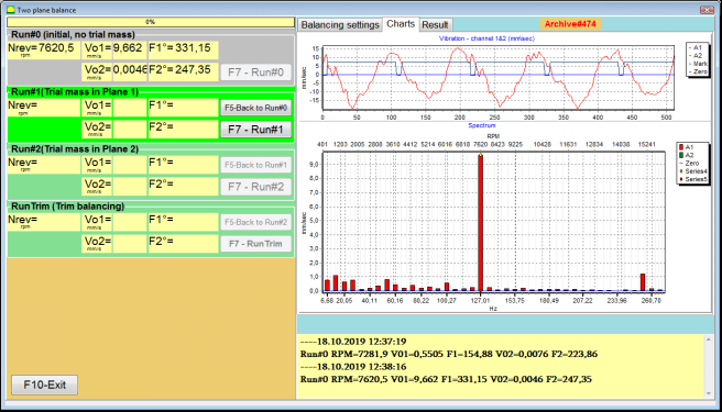
Fig. 7.35. రెండు ప్లేన్లలో బ్యాలెన్సింగ్లో ప్రారంభ రన్ తర్వాత కొలత ఫలితాలు.
⚠️ శ్రద్ధ వహించండి! కొలత ప్రారంభించే ముందు, బ్యాలెన్సింగ్ మెషీన్ యొక్క రోటర్ భ్రమణాన్ని (మొదటి రన్) ఆన్ చేసి, అది స్థిరమైన వేగంతో ఆపరేటింగ్ మోడ్లోకి ప్రవేశించిందని నిర్ధారించుకోవడం అవసరం.
వైబ్రేషన్ పారామీటర్లను కొలవడానికి Run#0 విభాగంలో, "F7 – Run#0" బటన్ క్లిక్ చేయండి (లేదా కంప్యూటర్ కీబోర్డ్పై F7 కీ నొక్కండి)
రోటర్ వేగం (RPM), 1x వైబ్రేషన్ యొక్క RMS విలువ (VО1, VО2) మరియు ఫేజ్లు (F1, F2) యొక్క కొలత ఫలితాలు Run#0 విభాగం యొక్క సంబంధిత విండోలలో కనిపిస్తాయి. Run#0 విభాగం.
రన్#1. తలం1లో ట్రయల్ ద్రవ్యరాశి
"రన్#1. తలం1లో ట్రయల్ ద్రవ్యరాశి” విభాగంలో, బ్యాలెన్సింగ్ మెషీన్ యొక్క రోటర్ భ్రమణాన్ని ఆపి, దానిపై ట్రయల్ వెయిట్ను అమర్చాలి, దాని ద్రవ్యరాశి “ట్రయల్ బరువు ద్రవ్యరాశి" విభాగం.
⚠️ శ్రద్ధ వహించండి!
- 1. ట్రయల్ వెయిట్ల ద్రవ్యరాశి మరియు బ్యాలెన్సింగ్ మెషీన్ రోటర్పై వాటి ఇన్స్టాలేషన్ స్థానాల ఎంపిక గురించి Appendix 1 లో వివరంగా చర్చించబడింది.
- ఉపయోగించవలసిన అవసరం ఉంటే సేవ్ చేసిన గుణకాలు భవిష్యత్తు పనిలో మోడ్, ట్రయల్ బరువును స్థాపించే ప్రదేశం దశ కోణాన్ని చదవడానికి ఉపయోగించే మార్కును స్థాపించే ప్రదేశంతో తప్పనిసరిగా సరిపోలాలి.
దీని తర్వాత, బ్యాలెన్సింగ్ యంత్రం యొక్క రోటర్ భ్రమణాన్ని మళ్లీ ఆన్ చేయడం అవసరం మరియు అది పనిచేసే మోడ్లోకి ప్రవేశించిందని నిర్ధారించుకోండి.
"రన్ # 1. తలం1లో ట్రయల్ ద్రవ్యరాశి" విభాగంలో vibration కొలత చేయడానికి, "F7 – రన్ #1" బటన్ను క్లిక్ చేయండి (లేదా కంప్యూటర్ కీబోర్డ్లో F7 కీ నొక్కండి).
కొలత ప్రక్రియ విజయవంతంగా పూర్తయిన తర్వాత, మీరు కొలత ఫలితాల ట్యాబ్కు తిరిగి వస్తారు.
ఈ సందర్భంలో, "రన్#1. తలం1లో ట్రయల్ ద్రవ్యరాశి” విభాగంలో రోటర్ వేగం (RPM) కొలత ఫలితాలతో పాటు, 1x వైబ్రేషన్ యొక్క RMS భాగాల విలువలు (Vо1, Vо2) మరియు ఫేజ్లు (F1, F2) కనిపిస్తాయి.
"రన్ # 2. ప్లేన్ 2లో ట్రయల్ మాస్"
"రన్ # 2. తలం2లో ట్రయల్ ద్రవ్యరాశి" విభాగంలో వైబ్రేషన్ పారామీటర్లను కొలవడం ప్రారంభించే ముందు, ఈ క్రింది దశలను నిర్వహించాలి:
- బ్యాలెన్సింగ్ మిషన్ యొక్క రోటర్ తిరుగుదలను ఆపండి;
- ప్లేన్ 1లో అమర్చిన ట్రయల్ వెయిట్ను తొలగించండి;
- ప్లేన్ 2లో ట్రయల్ వెయిట్ అమర్చండి, ద్రవ్యరాశిని "ట్రయల్ బరువు ద్రవ్యరాశి".
దీని తర్వాత, బ్యాలెన్సింగ్ యంత్రం యొక్క రోటర్ భ్రమణాన్ని ఆన్ చేయండి మరియు అది పనిచేసే వేగానికి చేరుకుందని నిర్ధారించుకోండి.
"రన్ # 2. తలం2లో ట్రయల్ ద్రవ్యరాశి" విభాగంలో vibration కొలత చేయడానికి, "F7 – రన్ # 2" బటన్ (లేదా కంప్యూటర్ కీబోర్డ్పై F7 కీ నొక్కండి). అప్పుడు "ఫలితం" ట్యాబ్ తెరుచుకుంటుంది.
ఉపయోగించే సందర్భంలో బరువు అమర్చే పద్ధతి" - "స్వేచ్ఛా స్థానాలు, డిస్ప్లేలో కరెక్టివ్ వెయిట్ల ద్రవ్యరాశి విలువలు (M1, M2) మరియు ఇన్స్టాలేషన్ కోణాలు (f1, f2) చూపబడతాయి.
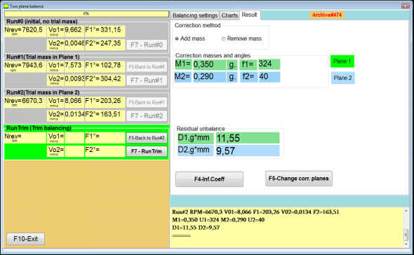
చిత్రం 7.36. సవరణ బరువుల లెక్కింపు ఫలితాలు – స్వేచ్ఛా స్థానం
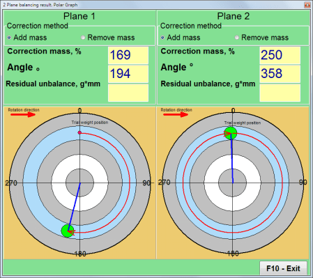
Fig. 7.37. కరెక్టివ్ వెయిట్ల లెక్కింపు ఫలితాలు – ఫ్రీ పొజిషన్. పోలార్ డయాగ్రమ్
బరువు అటాచ్మెంట్ పద్ధతిని ఉపయోగించే సందర్భంలో" – "స్థిర స్థానాలు

చిత్రం 7.38. దిద్దుబాటు భారాల లెక్కింపు ఫలితాలు – స్థిర స్థానం.
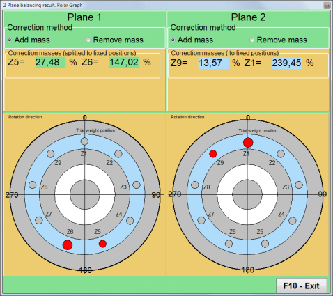
చిత్రం 7.39. సవరణ బరువుల లెక్కింపు ఫలితాలు – స్థిర స్థానం. ధ్రువ రేఖాచిత్రం.
"బరువు అమర్చే పద్ధతి" ఉపయోగించే సందర్భంలో – "వృత్తాకార గాడి"
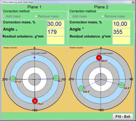
చిత్రం 7.40. దిద్దుబాటు భారాల లెక్కింపు ఫలితాలు – వృత్తాకార చీలిక.
⚠️ శ్రద్ధ వహించండి!
- కొలత ప్రక్రియను పూర్తి చేసిన తర్వాత రన్#2 బ్యాలెన్సింగ్ యంత్రం యొక్క, రోటర్ భ్రమణాన్ని ఆపివేయండి మరియు ముందుగా స్థాపించబడిన ట్రయల్ బరువును తొలగించండి. అప్పుడు మీరు సవరణ బరువులను స్థాపించవచ్చు (లేదా తొలగించవచ్చు).
- ధ్రువ అక్షాంశ వ్యవస్థలో దిద్దుబాటు భారాల కోణ స్థానాన్ని, పరీక్ష భారం అమర్చిన స్థానం నుండి రోటర్ భ్రమణ దిశలో లెక్కిస్తారు.
- "స్థిర స్థానం" - 1st స్థానం (Z1), ట్రయల్ బరువు ఏర్పాటు చేయబడిన స్థానంతో సరిపోలుతుంది. స్థానం సంఖ్య యొక్క లెక్కింపు దిశ రోటర్ యొక్క భ్రమణ దిశలో ఉంటుంది.
- 4. డిఫాల్ట్గా కరెక్షన్ వెయిట్ రోటర్కు జోడించబడుతుంది. దీనిని “జోడించు" ఫీల్డ్. బరువును తొలగిస్తున్నప్పుడు (ఉదాహరణకు, డ్రిల్లింగ్ ద్వారా), మీరు "తొలగించు” ఫీల్డ్లో గుర్తు పెట్టాలి, దాని తర్వాత కరెక్షన్ వెయిట్ యొక్క కోణీయ స్థానం స్వయంచాలకంగా 180º మారుతుంది.
రన్C (ట్రిమ్ రన్)
బ్యాలెన్సింగ్ రోటర్పై సవరణ బరువును స్థాపించిన తర్వాత, RunC (ట్రిమ్) నిర్వహించడం మరియు నిర్వహించబడిన బ్యాలెన్సింగ్ ప్రభావవంతతను అంచనా వేయడం అవసరం.
⚠️ శ్రద్ధ వహించండి! టెస్ట్ రన్ వద్ద కొలత ప్రారంభించే ముందు, యంత్రం యొక్క రోటర్ భ్రమణాన్ని ఆన్ చేసి, అది ఆపరేటింగ్ వేగానికి చేరుకుందని నిర్ధారించుకోవడం అవసరం.
RunTrim (బ్యాలెన్సింగ్ నాణ్యతను తనిఖీ చేయండి) విభాగంలో కంపన పారామీటర్లను కొలవడానికి, "F7 – RunTrim" బటన్ను క్లిక్ చేయండి (లేదా కంప్యూటర్ కీబోర్డ్లో F7 కీ నొక్కండి).
రోటర్ భ్రమణ పౌనఃపున్యం (RPM) కొలత ఫలితాలు, అలాగే RMS భాగం (Vо1) మరియు 1x కంపనం యొక్క దశ (F1) విలువ చూపబడతాయి.
"ఫలితం" ట్యాబ్ పని విండో కుడి వైపున కొలత ఫలితాల పట్టికతో కనిపిస్తుంది, ఇందులో అదనపు దిద్దుబాటు భారాల పారామీటర్ల లెక్కింపు ఫలితాలు ప్రదర్శించబడతాయి.
ఈ బరువులను ఇప్పటికే రోటర్పై స్థాపించబడిన సవరణ బరువులకు జోడించవచ్చు, మిగిలి ఉన్న అసమతౌల్యతను పరిహరించడానికి.
అదనంగా, బ్యాలెన్సింగ్ తర్వాత సాధించబడిన మిగిలి ఉన్న రోటర్ అసమతౌల్యత ఈ విండో యొక్క క్రింది భాగంలో చూపబడుతుంది.
సమతుల్యం చేసిన రోటర్ యొక్క అవశేష కంపనం మరియు/లేదా అవశేష అసమతుల్యత విలువలు సాంకేతిక పత్రాల్లో నిర్ణయించిన సహనం అవసరాలను తీర్చినప్పుడు, బ్యాలెన్సింగ్ ప్రక్రియను పూర్తి చేయవచ్చు.
ఇతర విధంగా, బ్యాలెన్సింగ్ ప్రక్రియ కొనసాగవచ్చు. ఇది బ్యాలెన్స్ చేయబడిన రోటర్పై కరెక్షన్ బరువును ఇన్స్టాల్ (తొలగించడం) చేసేటప్పుడు సంభవించే సాధ్యమయ్యే లోపాలను సరిచేయడానికి క్రమబద్ధమైన సమీపనల పద్ధతిని అనుమతిస్తుంది.
బ్యాలెన్సింగ్ రోటర్పై బ్యాలెన్సింగ్ ప్రక్రియను కొనసాగిస్తున్నప్పుడు, అదనపు కరెక్షన్ ద్రవ్యరాశిని అమర్చడం (తొలగించడం) అవసరం, దీని పారామితులు “Result” విండోలో సూచించబడతాయి.
"ఫలితం" విండోలో రెండు నియంత్రణ బటన్లు ఉపయోగించవచ్చు - "F4-ప్రభావ గుణ.", "F5 – దిద్దుబాటు తలాలను మార్చండి".
ప్రభావ గుణకాలు (2 తలాలు)
"F4-ప్రభావ గుణ.” బటన్ (లేదా కంప్యూటర్ కీబోర్డ్లోని F4 ఫంక్షన్ కీ) రెండు కాలిబ్రేషన్ స్టార్ట్ల ఫలితాల నుండి లెక్కించిన రోటర్ బ్యాలెన్సింగ్ గుణకాలను కంప్యూటర్ మెమరీలో వీక్షించడానికి మరియు సేవ్ చేయడానికి ఉపయోగించబడుతుంది.
అది నొక్కినప్పుడు, "ప్రభావ గుణకాలు (రెండు తలాలు)" పని విండో కంప్యూటర్ డిస్ప్లేపై కనిపిస్తుంది, ఇందులో మొదటి మూడు క్రమాంకన స్టార్టప్ల ఫలితాల ఆధారంగా లెక్కించిన బ్యాలెన్సింగ్ గుణకాలు ప్రదర్శించబడతాయి.

చిత్రం 7.41. 2 ప్లేన్లలో బ్యాలెన్సింగ్ గుణకాలతో పని విండో.
భవిష్యత్తులో ఇదే రకమైన యంత్రాన్ని బ్యాలెన్స్ చేసేటప్పుడు, “సేవ్ చేసిన గుణకాలు" మోడ్ మరియు కంప్యూటర్ మెమరీలో సేవ్ అయిన బ్యాలెన్సింగ్ గుణకాలు.
గుణకాలను సేవ్ చేయడానికి, "F9 – సేవ్" బటన్ నొక్కి, "ప్రభావ గుణకాల ఆర్కైవ్ (2తలాలు)" విండోలు (చిత్రం 7.42 చూడండి)
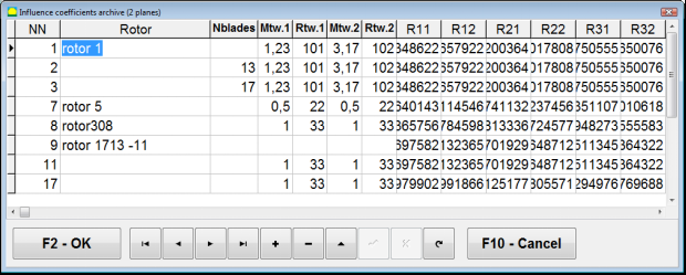
చిత్రం 7.42. 2 ప్లేన్లలో బ్యాలెన్సింగ్ గుణకాలతో పని విండో యొక్క రెండవ పేజీ.
కరెక్షన్ ప్లేన్లను మార్చండి
"F5 – దిద్దుబాటు తలాలను మార్చండి" బటన్ను దిద్దుబాటు తలాల స్థానాన్ని మార్చవలసినప్పుడు, అంటే దిద్దుబాటు భారాల ద్రవ్యరాశులు మరియు అమర్చే కోణాలను తిరిగి లెక్కించాల్సినప్పుడు ఉపయోగిస్తారు.
ఈ మోడ్ ప్రధానంగా సంక్లిష్ట ఆకారం ఉన్న రోటర్లను బ్యాలెన్స్ చేసేటప్పుడు ఉపయోగపడుతుంది (ఉదాహరణకు, క్రాంక్షాఫ్ట్లు).
ఈ బటన్ నొక్కినప్పుడు, పని విండో "ఇతర సవరణ తలాలకు సవరణ బరువుల ద్రవ్యరాశి మరియు కోణం యొక్క మళ్ళీ లెక్కింపు" కంప్యూటర్ డిస్ప్లేపై చూపబడుతుంది.
ఈ పని విండోలో, సంబంధిత చిత్రాన్ని క్లిక్ చేయడం ద్వారా 4 సాధ్యమయ్యే ఎంపికలలో ఒకదాన్ని ఎంచుకోవాలి.
అసలు కరెక్షన్ ప్లేన్లు (Н1 మరియు Н2) ఆకుపచ్చ రంగులో గుర్తించబడ్డాయి, మరియు కొత్తవి (K1 మరియు K2), వేటికి తిరిగి లెక్కించబడుతుందో, ఎరుపు రంగులో గుర్తించబడ్డాయి.
అప్పుడు, "లెక్కింపు డేటా" విభాగంలో, అభ్యర్థించిన డేటాను నమోదు చేయండి, అందులో:
- సంబంధిత దిద్దుబాటు తలాల మధ్య దూరం (a, b, c);
- రోటర్పై దిద్దుబాటు భారాల అమర్పు వ్యాసార్థాల కొత్త విలువలు (R1', R2').
డేటా నమోదు చేసిన తర్వాత, "F9 – లెక్కించు"
లెక్కింపు ఫలితాలు (ద్రవ్యరాశులు M1, M2 మరియు కరెక్షన్ వెయిట్ల ఇన్స్టాలేషన్ కోణాలు f1, f2) ఈ వర్కింగ్ విండో యొక్క సంబంధిత విభాగంలో ప్రదర్శించబడతాయి.
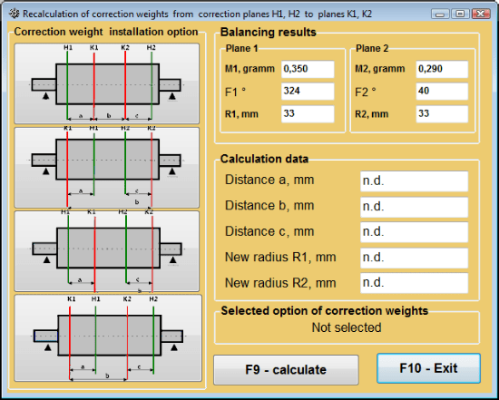
చిత్రం 7.43 దిద్దుబాటు తలాలను మార్చడం. దిద్దుబాటు ద్రవ్యరాశి మరియు కోణాన్ని ఇతర దిద్దుబాటు తలాలకు తిరిగి లెక్కించడం.
2 తలాల్లో బ్యాలెన్సింగ్కు సేవ్ చేసిన గుణకాలు
సేవ్ చేసిన గుణకాలతో బ్యాలెన్సింగ్ బ్యాలెన్సింగ్ గుణకాలు ఇప్పటికే నిర్ణయించబడి కంప్యూటర్ మెమరీలో నిల్వ చేయబడిన యంత్రంపై నిర్వహించబడవచ్చు.
⚠️ శ్రద్ధ వహించండి! మళ్ళీ బ్యాలెన్స్ చేసేటప్పుడు, కంపన సెన్సార్లు మరియు ఫేజ్ కోణ సెన్సార్ ప్రారంభ బ్యాలెన్సింగ్ సమయంలో ఉన్నట్లుగానే అదే విధంగా స్థాపించబడాలి.
తిరిగి బ్యాలెన్సింగ్ కోసం ప్రారంభ డేటా నమోదు "రెండు-ప్లేన్ బ్యాలెన్స్. బ్యాలెన్సింగ్ సెట్టింగ్స్".
ఈ సందర్భంలో, "ప్రభావ గుణకాలు" విభాగంలో, "సేవ్ చేసిన గుణకాలు" అంశంలో మొదలవుతుంది. ఈ సందర్భంలో, "ప్రభావ గుణకాల ఆర్కైవ్ (2తలాలు)" విండో కనిపిస్తుంది, ఇందులో ముందుగా నిర్ణయించిన బ్యాలెన్సింగ్ గుణకాల ఆర్కైవ్ సంగ్రహించబడి ఉంటుంది.
"►" లేదా "◄" control బటన్లను ఉపయోగించి ఈ archive యొక్క table ద్వారా కదులుతూ, మనకు అవసరమైన యంత్రం యొక్క balancing coefficients తో కావలసిన record ను ఎంచుకోవచ్చు. ఆపై, ప్రస్తుత కొలతలలో ఈ డేటాను ఉపయోగించడానికి, "F2 – OK” బటన్ను క్లిక్ చేసి మునుపటి వర్కింగ్ విండోకు తిరిగి వెళ్ళండి.
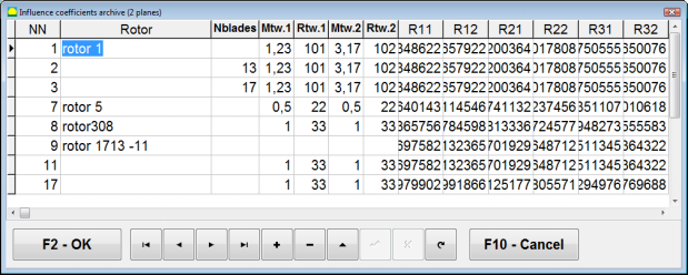
చిత్రం 7.44. 2 ప్లేన్లలో బ్యాలెన్సింగ్ గుణకాలతో పని విండో యొక్క రెండవ పేజీ.
ఆ తర్వాత “2 తలాల్లో బ్యాలెన్సింగ్. మూల డేటా" స్వయంచాలకంగా నింపబడుతుంది.
సేవ్ చేసిన గుణ. బ్యాలెన్సింగ్
"సేవ్ చేసిన గుణకాలు” బ్యాలెన్సింగ్కు కేవలం ఒక ట్యూనింగ్ స్టార్ట్ మరియు కనీసం ఒక టెస్ట్ స్టార్ట్ మాత్రమే అవసరం.
ట్యూనింగ్ ప్రారంభంలో కంపన కొలత (Run # 0) యంత్రం యొక్క కొలత "2 తలాలలో బ్యాలెన్సింగ్" బ్యాలెన్సింగ్ ఫలితాల పట్టికతో కూడిన పని విండోలో Run # 0 విభాగం.
⚠️ శ్రద్ధ వహించండి! కొలతను ప్రారంభించే ముందు, బ్యాలెన్సింగ్ యంత్రం యొక్క రోటర్ భ్రమణాన్ని ఆన్ చేసి, అది స్థిరమైన వేగంతో ఆపరేటింగ్ మోడ్లోకి ప్రవేశించిందని నిర్ధారించుకోవాలి.
వైబ్రేషన్ పారామీటర్లను కొలవడానికి Run # 0 విభాగంలో, "F7 – Run#0" బటన్ను క్లిక్ చేయండి (లేదా కంప్యూటర్ కీబోర్డ్లో F7 కీ నొక్కండి).
రోటర్ వేగం (RPM) కొలత ఫలితాలు, అలాగే 1x కంపనం యొక్క భాగాల యొక్క RMS (VО1, VО2) మరియు ఫేజ్ల (F1, F2) విలువలు సంబంధిత ఫీల్డ్లలో కనిపిస్తాయి Run # 0 విభాగం.
అదే సమయంలో, "ఫలితం" ట్యాబ్ తెరుచుకుంటుంది, ఇందులో రోటర్పై అమర్చాల్సిన దిద్దుబాటు భారాల పారామీటర్ల లెక్కింపు ఫలితాలు ప్రదర్శించబడతాయి, ఇవి దాని అసమతుల్యతను భర్తీ చేస్తాయి.
అంతేకాకుండా, ధ్రువ అక్షాంశ వ్యవస్థ ఉపయోగించినప్పుడు, డిస్ప్లేలో దిద్దుబాటు భారాల ద్రవ్యరాశి విలువలు మరియు అమర్పు కోణాలు చూపబడతాయి.
సవరణ బరువులను బ్లేడ్లపై విభజించే సందర్భంలో, బ్యాలెన్సింగ్ రోటర్ యొక్క బ్లేడ్ల సంఖ్య మరియు వాటిపై స్థాపించాల్సిన బరువు యొక్క ద్రవ్యరాశి ప్రదర్శించబడతాయి.
తర్వాత, ప్రాథమిక బ్యాలెన్సింగ్ కోసం విభాగం 7.6.1.2లో ఉన్న సిఫార్సుల ప్రకారం బ్యాలెన్సింగ్ ప్రక్రియ నిర్వహించబడుతుంది.
⚠️ శ్రద్ధ వహించండి!
- బ్యాలెన్స్ చేయబడిన యంత్రం యొక్క రెండవ స్టార్ట్ తర్వాత కొలత ప్రక్రియ పూర్తయిన తర్వాత, దాని రోటర్ భ్రమణాన్ని ఆపి, ముందుగా అమర్చిన ట్రయల్ బరువును తొలగించాలి. అప్పుడే మీరు రోటర్పై సవరణ బరువును స్థాపించడానికి (లేదా తొలగించడానికి) ప్రారంభించవచ్చు.
- రోటర్పై సవరణ బరువును జోడించే (లేదా తొలగించే) చోటి కోణీయ స్థానాన్ని లెక్కించడం పోలార్ కోఆర్డినేట్ సిస్టమ్లో ట్రయల్ బరువు స్థాపన స్థలంపై నిర్వహించబడుతుంది. లెక్కింపు దిశ రోటర్ భ్రమణ కోణ దిశతో సరిపోలుతుంది.
- రెక్కలపై బ్యాలెన్సింగ్ చేసే సందర్భంలో – స్థానం 1గా గుర్తించిన సమతుల్యం చేసిన రోటర్ రెక్క, పరీక్ష భారం అమర్చిన స్థానంతో సమానంగా ఉంటుంది. కంప్యూటర్ డిస్ప్లేపై చూపబడే రెక్క సంఖ్య దిశ రోటర్ భ్రమణ దిశలో అనుసరించబడుతుంది.
- ప్రోగ్రామ్ యొక్క ఈ వెర్షన్లో, రోటర్పై కరెక్షన్ వెయిట్ జోడించబడుతుందని డిఫాల్ట్గా అంగీకరించబడింది. దీనిని "Addition" ఫీల్డ్లో ఏర్పాటు చేయబడిన ట్యాగ్ నిరూపిస్తుంది. వెయిట్ తొలగింపు ద్వారా అసమతుల్యతను సరిచేయడం (ఉదాహరణకు, డ్రిల్లింగ్ ద్వారా) అవసరమైతే, "Removal" ఫీల్డ్లో ట్యాగ్ ఏర్పాటు చేయాలి; అప్పుడు కరెక్షన్ వెయిట్ యొక్క కోణీయ స్థానం స్వయంచాలకంగా 180º మారుతుంది.
మాండ్రెల్ ఎక్సెంట్రిసిటీ తొలగింపు (ఇండెక్స్ బ్యాలెన్సింగ్) - రెండు ప్లేన్లు
బ్యాలెన్సింగ్ సమయంలో రోటర్ను సిలిండరికల్ మాండ్రెల్లో స్థాపించినట్లయితే, మాండ్రెల్ యొక్క ఎక్సెంట్రిసిటీ అదనపు దోషాన్ని ప్రవేశపెట్టవచ్చు. ఈ దోషాన్ని తొలగించడానికి, రోటర్ను మాండ్రెల్లో 180 డిగ్రీలు తిప్పి అదనపు స్టార్ట్ చేయాలి. దీనిని ఇండెక్స్ బ్యాలెన్సింగ్ అంటారు.
ఇండెక్స్ బ్యాలెన్సింగ్ నిర్వహించడానికి, Balanset-1A ప్రోగ్రామ్లో ఒక ప్రత్యేక ఆప్షన్ అందుబాటులో ఉంది. మాండ్రెల్ ఎక్సెంట్రిసిటీ ఎలిమినేషన్ ఛెక్ చేసినప్పుడు, బ్యాలెన్సింగ్ విండోలో అదనపు RunEcc సెక్షన్ కనిపిస్తుంది.
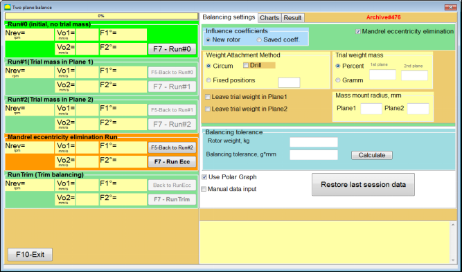
చిత్రం 7.45. ఇండెక్స్ బ్యాలెన్సింగ్ కోసం పని విండో.
Run # 2 (Trial mass Plane 2) నడుపిన తర్వాత, ఒక విండో కనిపిస్తుంది
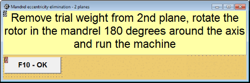
చిత్రం 7.46. హెచ్చరిక విండోలు
రోటర్ను 180° తిప్పి అమర్చిన తర్వాత, Run Ecc పూర్తి చేయాలి. మాండ్రెల్ ఎక్సెంట్రిసిటీని ప్రభావితం చేయకుండా ప్రోగ్రామ్ నిజమైన రోటర్ అసమతుల్యతను స్వయంచాలకంగా లెక్కిస్తుంది.
7.6 చార్ట్స్ మోడ్
"Charts" మోడ్లో పని చేయడం ప్రారంభ విండో నుండి (చూ. Fig. 7.1) "F8 – Charts" నొక్కడం ద్వారా ప్రారంభమవుతుంది. తర్వాత "రెండు చానెల్లలో వైబ్రేషన్ కొలత. Charts" విండో (చూ. Fig. 7.19) తెరుచుకుంటుంది.

Fig. 7.47. ఆపరేటింగ్ విండో "రెండు చానెల్లలో వైబ్రేషన్ కొలత. Charts".
ఈ మోడ్లో పని చేస్తున్నప్పుడు నాలుగు రకాల కంపన చార్ట్లను గీయడం సాధ్యమవుతుంది.
మొదటి రకం మొదటి మరియు రెండవ కొలత ఛానెల్లపై మొత్తం కంపనం యొక్క (కంపన వేగం యొక్క) సమయ ఫంక్షన్ను పొందడానికి అనుమతిస్తుంది.
రెండవ రకం భ్రమణ పౌనఃపున్యం మరియు దాని అధిక హార్మోనిక్ భాగాలపై సంభవించే కంపనం యొక్క (కంపన వేగం యొక్క) గ్రాఫ్లను పొందడానికి అనుమతిస్తుంది.
ఈ గ్రాఫ్లు మొత్తం కంపన సమయ ఫంక్షన్ యొక్క సింక్రోనస్ ఫిల్టరింగ్ ఫలితంగా పొందబడతాయి.
మూడవ రకం హార్మోనిక్ విశ్లేషణ ఫలితాలతో కంపన చార్ట్లను అందిస్తుంది.
నాలుగవ రకం స్పెక్ట్రమ్ విశ్లేషణ ఫలితాలతో కంపన చార్ట్ను పొందడానికి అనుమతిస్తుంది.
మొత్తం కంపన చార్ట్లు
మొత్తం వైబ్రేషన్ చార్ట్ రూపొందించడానికి "రెండు ఛానెల్లపై కంపన కొలత. చార్ట్లు" ఆపరేటింగ్ విండోలో ఆపరేటింగ్ మోడ్ ఎంచుకోవడం అవసరం "మొత్తం వైబ్రేషన్” తగిన బటన్ను క్లిక్ చేయడం ద్వారా ఎంచుకోవాలి. తర్వాత «▼» బటన్ను క్లిక్ చేసి “Duration, in seconds” బాక్స్లో వైబ్రేషన్ కొలత వ్యవధిని సెట్ చేయండి మరియు డ్రాప్-డౌన్ జాబితా నుండి కావలసిన కొలత వ్యవధిని ఎంచుకోండి, ఇది 1, 5, 10, 15 లేదా 20 సెకన్లకు సమానంగా ఉండవచ్చు;
సిద్ధంగా ఉన్నప్పుడు "F9-Measure" బటన్ నొక్కండి (క్లిక్ చేయండి), అప్పుడు రెండు చానెల్లలో ఏకకాలంలో వైబ్రేషన్ కొలత ప్రక్రియ ప్రారంభమవుతుంది.
కొలత ప్రక్రియ పూర్తయిన తర్వాత ఆపరేటింగ్ విండోలో మొదటి (ఎరుపు) మరియు రెండవ (ఆకుపచ్చ) ఛానెల్ల యొక్క మొత్తం కంపనం యొక్క సమయ ఫంక్షన్ యొక్క చార్ట్లు కనిపిస్తాయి (చూ. చిత్రం 7.47).
ఈ చార్ట్లపై X-అక్షంపై సమయం గీయబడుతుంది మరియు Y-అక్షంపై కంపన వేగం యొక్క ఆంప్లిట్యూడ్ (mm/sec) గీయబడుతుంది.
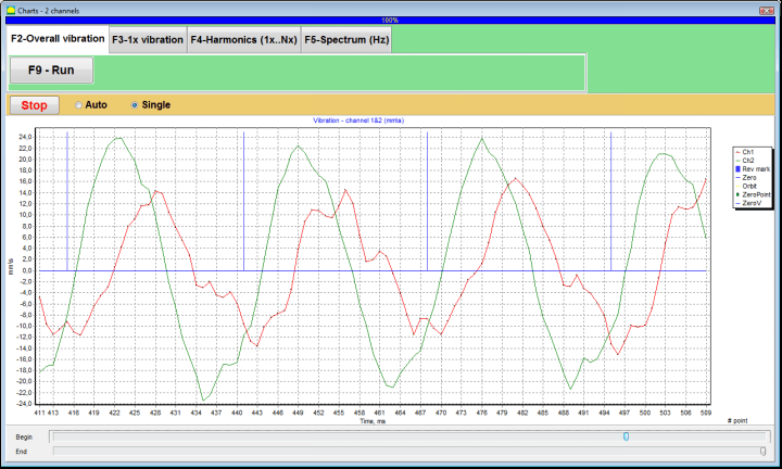
Fig. 7.48. మొత్తం వైబ్రేషన్ చార్ట్ల టైమ్ ఫంక్షన్ అవుట్పుట్ కోసం ఆపరేటింగ్ విండో
రోటర్ యొక్క భ్రమణ పౌనఃపున్యంతో మొత్తం కంపన చార్ట్లను కలుపుతూ ఈ గ్రాఫ్లలో గుర్తులు (నీలం రంగులో) కూడా ఉన్నాయి. అదనంగా, ప్రతి గుర్తు రోటర్ యొక్క తర్వాతి భ్రమణం యొక్క ప్రారంభాన్ని (ముగింపును) సూచిస్తుంది.
X-అక్షంపై చార్ట్ యొక్క స్కేల్ మార్పు అవసరమైతే, చిత్రం 7.20లో బాణం సూచించిన స్లైడర్ను ఉపయోగించవచ్చు.
1x వైబ్రేషన్ చార్ట్లు
1x వైబ్రేషన్ చార్ట్ రూపొందించడానికి "రెండు ఛానెల్లపై కంపన కొలత. చార్ట్లు" ఆపరేటింగ్ విండోలో ఆపరేటింగ్ మోడ్ ఎంచుకోవడం అవసరం "1x కంపనం" తగిన బటన్ క్లిక్ చేయడం ద్వారా.
అప్పుడు "1x కంపనం" అనే ఆపరేటింగ్ విండో కనిపిస్తుంది.
"F9-Measure" బటన్ నొక్కండి (క్లిక్ చేయండి), అప్పుడు రెండు చానెల్లలో ఏకకాలంలో వైబ్రేషన్ కొలత ప్రక్రియ ప్రారంభమవుతుంది.
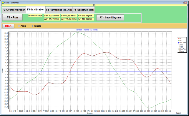
Fig. 7.49. 1x వైబ్రేషన్ చార్ట్ల అవుట్పుట్ కోసం ఆపరేటింగ్ విండో.
కొలత ప్రక్రియ పూర్తయిన తర్వాత మరియు ఫలితాల గణిత లెక్కింపు (మొత్తం కంపనం యొక్క సమయ ఫంక్షన్ యొక్క సింక్రోనస్ ఫిల్టరింగ్) తర్వాత ప్రధాన విండోలో డిస్ప్లేపై సమానమైన సమయం కోసం రోటర్ యొక్క ఒక పూర్తి భ్రమణం చార్ట్లు కనిపిస్తాయి: 1x కంపనం రెండు ఛానళ్లపై.
ఈ సందర్భంలో, మొదటి ఛానెల్ కోసం చార్ట్ ఎరుపు రంగులో మరియు రెండవ ఛానెల్ కోసం ఆకుపచ్చ రంగులో చిత్రించబడుతుంది. ఈ చార్ట్లపై X-అక్షంపై రోటర్ భ్రమణ కోణం (గుర్తు నుండి గుర్తు వరకు) గీయబడుతుంది మరియు Y-అక్షంపై కంపన వేగం యొక్క ఆంప్లిట్యూడ్ (mm/sec) గీయబడుతుంది.
అదనంగా, వర్కింగ్ విండో యొక్క పై భాగంలో (బటన్కు కుడి వైపున “F9 – కొలవండి") రెండు చానెల్ల వైబ్రేషన్ కొలతల సంఖ్యాత్మక విలువలు, "వైబ్రేషన్ మీటర్" మోడ్లో మనం పొందే విలువలతో సమానంగా, ప్రదర్శించబడతాయి.
ముఖ్యంగా: మొత్తం కంపనం యొక్క RMS విలువ (V1s, V2s), RMS పరిమాణం (V1o, V2o) మరియు దశ (Fi, Fj) 1x కంపనం మరియు రోటర్ వేగం (Nrev) యొక్క.
హార్మోనిక్ విశ్లేషణ ఫలితాలతో వైబ్రేషన్ చార్ట్లు
హార్మోనిక్ విశ్లేషణ ఫలితాలతో చార్ట్ రూపొందించడానికి "రెండు ఛానెల్లపై కంపన కొలత. చార్ట్లు" ఆపరేటింగ్ విండోలో ఆపరేటింగ్ మోడ్ ఎంచుకోవడం అవసరం "హార్మోనిక్ విశ్లేషణ" తగిన బటన్ క్లిక్ చేయడం ద్వారా.
తర్వాత రోటర్ భ్రమణ ఫ్రీక్వెన్సీకి సమానమైన లేదా గుణిజమైన పీరియడ్ కలిగిన వైబ్రేషన్ హార్మోనిక్ కాంపోనెంట్ల టైమ్ ఫంక్షన్ చార్ట్లు మరియు స్పెక్ట్రమ్లను ఏకకాలంలో ప్రదర్శించే ఆపరేటింగ్ విండో కనిపిస్తుంది.
గమనిక!
ఈ మోడ్లో పనిచేసేటప్పుడు, సెన్సార్ అమర్చిన యంత్రం యొక్క రోటర్ ఫ్రీక్వెన్సీతో కొలత ప్రక్రియను సమకాలీకరించే ఫేజ్ యాంగిల్ సెన్సార్ను ఉపయోగించడం అవసరం.
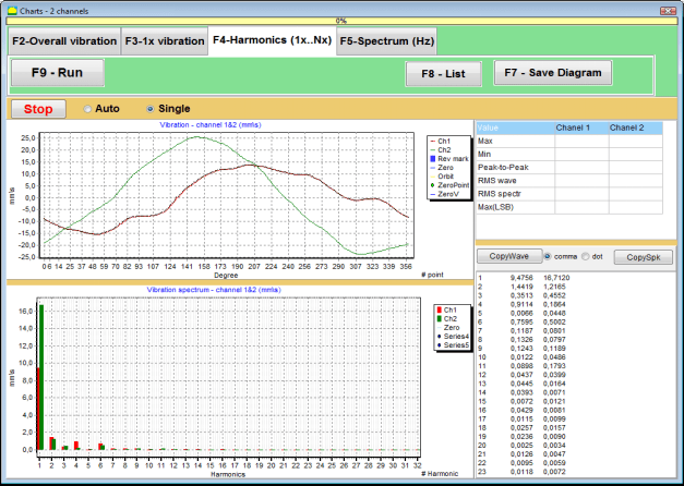
Fig. 7.50. 1x వైబ్రేషన్ హార్మోనిక్ల ఆపరేటింగ్ విండో.
సిద్ధంగా ఉన్నప్పుడు "F9-Measure" బటన్ నొక్కండి (క్లిక్ చేయండి), అప్పుడు రెండు చానెల్లలో ఏకకాలంలో వైబ్రేషన్ కొలత ప్రక్రియ ప్రారంభమవుతుంది.
కొలత ప్రక్రియ పూర్తయిన తర్వాత ఆపరేటింగ్ విండోలో టైమ్ ఫంక్షన్ చార్ట్లు (పైన చార్ట్) మరియు 1x వైబ్రేషన్ హార్మోనిక్లు (క్రింద చార్ట్) కనిపిస్తాయి.
హార్మోనిక్ భాగాల సంఖ్య X-అక్షంపై గీయబడుతుంది మరియు కంపన వేగం యొక్క RMS (mm/sec) Y-అక్షంపై గీయబడుతుంది.
వైబ్రేషన్ టైమ్ డొమైన్ మరియు స్పెక్ట్రమ్ చార్ట్లు
స్పెక్ట్రమ్ చార్ట్ రూపొందించడానికి ఉపయోగించండి "F5-స్పెక్ట్రం" ట్యాబ్:
తర్వాత వేవ్ మరియు వైబ్రేషన్ స్పెక్ట్రమ్ చార్ట్లను ఏకకాలంలో అవుట్పుట్ చేయడానికి ఆపరేటింగ్ విండో కనిపిస్తుంది.

Fig. 7.51. వైబ్రేషన్ స్పెక్ట్రమ్ అవుట్పుట్ కోసం ఆపరేటింగ్ విండో.
సిద్ధంగా ఉన్నప్పుడు "F9-Measure" బటన్ నొక్కండి (క్లిక్ చేయండి), అప్పుడు రెండు చానెల్లలో ఏకకాలంలో వైబ్రేషన్ కొలత ప్రక్రియ ప్రారంభమవుతుంది.
కొలత ప్రక్రియ పూర్తయిన తర్వాత ఆపరేటింగ్ విండోలో టైమ్ ఫంక్షన్ చార్ట్లు (పైన చార్ట్) మరియు వైబ్రేషన్ స్పెక్ట్రమ్ (క్రింద చార్ట్) కనిపిస్తాయి.
కంపన పౌనఃపున్యం X-అక్షంపై గీయబడుతుంది మరియు కంపన వేగం యొక్క RMS (mm/sec) Y-అక్షంపై గీయబడుతుంది.
ఈ సందర్భంలో, మొదటి ఛానెల్ కోసం గ్రాఫ్ ఎరుపు రంగులో మరియు రెండవ ఛానెల్ కోసం ఆకుపచ్చ రంగులో చూపబడుతుంది.
8. పరికరం యొక్క ఆపరేషన్ మరియు నిర్వహణపై సాధారణ సూచనలు
8.1 బ్యాలెన్సింగ్ నాణ్యత ప్రమాణాలు (ISO 2372 స్టాండర్డ్)
ISO 2372 ప్రమాణం ద్వారా నిర్ణయించబడిన వైబ్రేషన్ స్థాయిలను ఉపయోగించి బ్యాలెన్సింగ్ నాణ్యతను అంచనా వేయవచ్చు. క్రింది పట్టికలో వివిధ యంత్ర తరగతులకు అనుమతించదగిన వైబ్రేషన్ స్థాయిలు చూపబడ్డాయి:
| యంత్ర వర్గం | మంచిది (mm/sec RMS) |
ఆమోదయోగ్యం (mm/sec RMS) |
అంగీకార్య స్థాయి (mm/sec RMS) |
ఆమోదయోగ్యం కాదు (mm/sec RMS) |
|---|---|---|---|---|
| తరగతి 1 దృఢమైన పునాదులపై చిన్న యంత్రాలు (15 kW వరకు మోటార్లు) |
< 0.7 | 0.7 - 1.8 | 1.8 - 4.5 | > 4.5 |
| తరగతి 2 పునాదులు లేని మీడియం యంత్రాలు (15-75 kW మోటార్లు), 300 kW వరకు డ్రైవ్ మెకానిజమ్లు |
< 1.1 | 1.1 - 2.8 | 2.8 - 7.1 | > 7.1 |
| తరగతి 3 దృఢమైన పునాదులపై పెద్ద యంత్రాలు (300 kW కంటే అధికంగా పరికరాలు) |
< 1.8 | 1.8 - 4.5 | 4.5 - 11 | > 11 |
| తరగతి 4 తేలికపాటి పునాదులపై పెద్ద యంత్రాలు (300 kW కంటే అధికంగా పరికరాలు) |
< 2.8 | 2.8 - 7.1 | 7.1 - 18 | > 18 |
గమనిక: ఈ విలువలు బ్యాలెన్సింగ్ నాణ్యతను అంచనా వేయడానికి మార్గదర్శనం అందిస్తాయి. మీ అప్లికేషన్ కోసం నిర్దిష్ట పరికర తయారీదారు స్పెసిఫికేషన్లు మరియు వర్తించే ప్రమాణాలను ఎల్లప్పుడూ పాటించండి.
8.2 నిర్వహణ అవసరాలు
🔧 క్రమం తప్పకుండా నిర్వహణ
- ✓తయారీదారు స్పెసిఫికేషన్ల ప్రకారం సెన్సార్ల క్రమం తప్పకుండా క్యాలిబ్రేషన్
- ✓సెన్సార్లను పరిశుభ్రంగా మరియు అయస్కాంత శకలాల నుండి దూరంగా ఉంచండి
- ✓వినియోగంలో లేనప్పుడు పరికరాలను రక్షణ కేసులో నిల్వ చేయండి
- ✓లేజర్ సెన్సార్ను దుమ్ము మరియు తేమ నుండి రక్షించండి
- ✓కేబుల్ కనెక్షన్లను అరిగిపోవడం లేదా దెబ్బ కోసం క్రమం తప్పకుండా తనిఖీ చేయండి
- ✓తయారీదారు సిఫార్సు మేరకు సాఫ్ట్వేర్ను అప్డేట్ చేయండి
- ✓ముఖ్యమైన బ్యాలెన్సింగ్ డేటా యొక్క బ్యాకప్ కాపీలను నిర్వహించండి
📋 EU నిర్వహణ ప్రమాణాలు
పరికరాల నిర్వహణ వీటిని పాటించాలి:
- EN ISO 9001: నాణ్యత నిర్వహణ వ్యవస్థల అవసరాలు
- EN 13306: నిర్వహణ పరిభాష మరియు నిర్వచనాలు
- EN 15341: నిర్వహణ కీలక పనితీరు సూచికలు
- EU యంత్రాల నిర్దేశం ప్రకారం క్రమం తప్పకుండా భద్రతా తనిఖీలు
అనుబంధం 1. రోటర్ బ్యాలెన్సింగ్
రోటర్ అంటే ఒక నిర్దిష్ట అక్షం చుట్టూ తిరిగే ఒక వస్తువు, దీని బేరింగ్ ఉపరితలాలు దానిని సపోర్టులలో పట్టుకుంటాయి. రోటర్ యొక్క బేరింగ్ ఉపరితలాలు రోలింగ్ లేదా స్లైడింగ్ బేరింగుల ద్వారా సపోర్టులకు బరువులను బదిలీ చేస్తాయి. "బేరింగ్ ఉపరితలం" అనే పదాన్ని ఉపయోగించేటప్పుడు, మనం సాధారణంగా జర్నల్* లేదా జర్నల్ స్థానంలో ఉన్న ఉపరితలాలను సూచిస్తాము.
*జర్నల్ (జర్మన్లో Zapfen అంటే "జర్నల్", "పిన్") - ఇది ఒక హోల్డర్ (బేరింగ్ బాక్స్) ద్వారా మోయబడే షాఫ్ట్ లేదా అక్షంలోని ఒక భాగం.
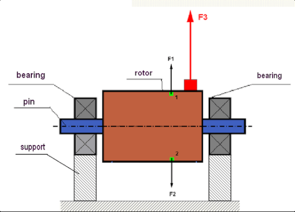
చిత్రం 1. రోటర్ మరియు అపకేంద్ర బలాలు.
పూర్తిగా బ్యాలెన్స్ చేయబడిన రోటర్లో, దాని ద్రవ్యరాశి భ్రమణ అక్షం చుట్టూ సౌష్టవంగా పంపిణీ చేయబడుతుంది. అంటే, రోటర్ యొక్క ఏ మూలకమైనా భ్రమణ అక్షం చుట్టూ సౌష్టవంగా ఉన్న మరొక మూలకంతో సరిపోల్చవచ్చు. భ్రమణ సమయంలో, ప్రతి రోటర్ మూలకంపై రేడియల్ దిశలో (రోటర్ భ్రమణ అక్షానికి లంబంగా) పనిచేసే అపకేంద్ర బలం పనిచేస్తుంది. బ్యాలెన్స్ చేయబడిన రోటర్లో, ఏ మూలకంపై పనిచేసే అపకేంద్ర బలం అయినా సౌష్టవ మూలకంపై పనిచేసే అపకేంద్ర బలం ద్వారా సమతుల్యం చేయబడుతుంది. ఉదాహరణకు, మూలకాలు 1 మరియు 2 (చిత్రం 1లో ఆకుపచ్చ రంగుతో చూపబడ్డాయి) పరిమాణంలో సమానమైన మరియు దిశలో పూర్తిగా వ్యతిరేకమైన అపకేంద్ర బలాలు F1 మరియు F2 చే ప్రభావితమవుతాయి. ఇది రోటర్ యొక్క అన్ని సౌష్టవ మూలకాలకు వర్తిస్తుంది, కాబట్టి రోటర్పై పనిచేసే మొత్తం అపకేంద్ర బలం 0కి సమానం మరియు రోటర్ బ్యాలెన్స్ చేయబడింది. కానీ రోటర్ యొక్క సౌష్టవం దెబ్బతింటే (చిత్రం 1లో, అసౌష్టవ మూలకం ఎరుపు రంగులో గుర్తించబడింది), అప్పుడు అసమతుల్య అపకేంద్ర బలం F3 రోటర్పై పనిచేయడం ప్రారంభిస్తుంది.
తిరిగేటప్పుడు, ఈ శక్తి రోటర్ భ్రమణంతో పాటు దిశను మారుస్తుంది. ఈ శక్తి వల్ల ఏర్పడే డైనమిక్ లోడ్ బేరింగులకు బదిలీ అవుతుంది, దీనివల్ల వాటి వేగవంతమైన అరిగిపోత జరుగుతుంది. అంతేకాక, ఈ మారే శక్తి ప్రభావంతో, రోటర్ అమర్చిన సపోర్టులు మరియు ఫౌండేషన్లో చక్రీయ వైరూప్యం ఏర్పడుతుంది, ఇది వైబ్రేషన్ను ఉత్పత్తి చేస్తుంది. రోటర్ యొక్క అన్బ్యాలెన్స్ మరియు దానితో పాటు వచ్చే వైబ్రేషన్ను తొలగించడానికి, రోటర్ యొక్క సమరూపతను పునరుద్ధరించే బ్యాలెన్సింగ్ ద్రవ్యరాశులను అమర్చడం అవసరం.
రోటర్ బ్యాలెన్సింగ్ అనేది బ్యాలెన్సింగ్ ద్రవ్యరాశులను జోడించడం ద్వారా అసమతుల్యతను తొలగించే ఒక ప్రక్రియ.
బ్యాలెన్సింగ్ యొక్క లక్ష్యం ఒకటి లేదా అంతకంటే ఎక్కువ బ్యాలెన్సింగ్ ద్రవ్యరాశుల ఏర్పాటు స్థానాల (కోణాల) మరియు వాటి పరిమాణాన్ని కనుగొనడం.
రోటర్ రకాలు మరియు అన్బ్యాలెన్స్
రోటర్ మెటీరియల్ యొక్క బలాన్ని మరియు దానిపై పనిచేసే అపకేంద్ర బలాల పరిమాణాన్ని పరిగణనలోకి తీసుకుంటే, రోటర్లను రెండు రకాలుగా విభజించవచ్చు: దృఢమైనవి (రిజిడ్) మరియు వంచదగినవి (ఫ్లెక్సిబుల్).
ఆపరేటింగ్ పరిస్థితుల్లో దృఢమైన రోటర్లు అపకేంద్ర బలం ప్రభావంతో స్వల్పంగా వంగవచ్చు, అయితే గణనలలో ఈ వంపు ప్రభావాన్ని విస్మరించవచ్చు.
మరోవైపు, ఫ్లెక్సిబుల్ రోటర్ల వంపును ఎప్పుడూ విస్మరించకూడదు. ఫ్లెక్సిబుల్ రోటర్ల వంపు బ్యాలెన్సింగ్ సమస్యకు పరిష్కారాన్ని క్లిష్టతరం చేస్తుంది మరియు దృఢ రోటర్లను బ్యాలెన్స్ చేసే పనితో పోలిస్తే వేరే గణిత నమూనాలను ఉపయోగించడం అవసరం చేస్తుంది. ఒకే రోటర్ తక్కువ భ్రమణ వేగాల వద్ద దృఢమైనదానిలా మరియు అధిక వేగాల వద్ద ఫ్లెక్సిబుల్దానిలా ప్రవర్తించగలదని గమనించడం ముఖ్యం. ఇక ముందు మేము దృఢ రోటర్ల బ్యాలెన్సింగ్ను మాత్రమే పరిగణలోకి తీసుకుంటాము.
రోటర్ పొడవు వెంట అన్బ్యాలెన్స్ అయిన ద్రవ్యరాశుల పంపిణీని బట్టి, రెండు రకాల అన్బ్యాలెన్స్లను వేరు చేయవచ్చు – స్టాటిక్ మరియు డైనమిక్. ఇదే విధంగా స్టాటిక్ మరియు డైనమిక్ రోటర్ బ్యాలెన్సింగ్కు కూడా వర్తిస్తుంది.
రోటర్ యొక్క స్టాటిక్ అన్బ్యాలెన్స్ రోటర్ భ్రమణం లేకుండానే సంభవిస్తుంది. మరో మాటలో చెప్పాలంటే, రోటర్ గురుత్వాకర్షణ ప్రభావంలో ఉన్నప్పుడు అది నిశ్చలంగా ఉంటుంది మరియు అదనంగా దాని “భారీ బిందువు”ను కిందికి తిప్పుతుంది. స్టాటిక్ అన్బ్యాలెన్స్ ఉన్న రోటర్ యొక్క ఉదాహరణ చిత్రం 2లో చూపబడింది.

చిత్రం 2
రోటర్ తిరిగేటప్పుడు మాత్రమే డైనమిక్ అన్బ్యాలెన్స్ సంభవిస్తుంది.
డైనమిక్ అసమతుల్యత కలిగిన రోటర్ యొక్క ఉదాహరణ చిత్రం 3లో చూపబడింది.
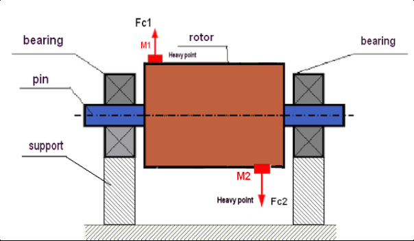
చిత్రం 3. రోటర్ యొక్క డైనమిక్ అసమతుల్యత – అపకేంద్ర బలాల జంట
ఈ సందర్భంలో, సమానమైన అసమతుల్య ద్రవ్యరాశులు M1 మరియు M2 వేర్వేరు తలాల్లో ఉంటాయి — రోటర్ పొడవు వెంబడి వేర్వేరు ప్రదేశాల్లో. స్టాటిక్ స్థితిలో, అంటే రోటర్ తిరగనప్పుడు, రోటర్పై గురుత్వాకర్షణ మాత్రమే పనిచేస్తుంది కాబట్టి ద్రవ్యరాశులు ఒకదానికొకటి సమతుల్యం చేసుకుంటాయి. రోటర్ తిరుగుతున్నప్పుడు డైనమిక్స్లో, M1 మరియు M2 ద్రవ్యరాశులపై అపకేంద్ర బలాలు FЎ1 మరియు FЎ2 పనిచేయడం మొదలవుతుంది. ఈ బలాలు పరిమాణంలో సమానంగా మరియు దిశలో వ్యతిరేకంగా ఉంటాయి. అయితే, అవి షాఫ్ట్ పొడవు వెంబడి వేర్వేరు ప్రదేశాల్లో ఉండి ఒకే రేఖపై లేనందున, ఈ బలాలు ఒకదానికొకటి రద్దు చేసుకోవు. FЎ1 మరియు FЎ2 బలాలు రోటర్పై పనిచేసే ఒక మొమెంట్ను సృష్టిస్తాయి. అందుకే ఈ అసమతుల్యతకు “మొమెంటరీ” అనే మరో పేరు ఉంది. తదనుగుణంగా, భర్తీ చేయని అపకేంద్ర బలాలు బేరింగ్ సపోర్ట్లపై పనిచేస్తాయి, ఇవి మనం అంచనా వేసిన బలాల కంటే గణనీయంగా ఎక్కువగా ఉండి బేరింగ్ల సేవా జీవితకాలాన్ని కూడా తగ్గించగలవు.
ఈ రకమైన అసమతుల్యత రోటర్ తిరిగేటప్పుడు డైనమిక్స్లో మాత్రమే సంభవిస్తుంది కాబట్టి, దీనిని డైనమిక్ అసమతుల్యత అంటారు. దీనిని స్టాటిక్ బ్యాలెన్సింగ్ (అంటే “నైవ్స్పై” అని పిలవబడే పద్ధతి) ద్వారా గానీ, మరే ఇతర సారూప్య పద్ధతి ద్వారా గానీ తొలగించలేము. డైనమిక్ అసమతుల్యతను తొలగించడానికి, M1 మరియు M2 ద్రవ్యరాశుల నుండి ఏర్పడే మొమెంట్కు పరిమాణంలో సమానంగా మరియు దిశలో వ్యతిరేకంగా ఉండే మొమెంట్ను సృష్టించే రెండు పరిహార బరువులను అమర్చడం అవసరం. పరిహార ద్రవ్యరాశులు తప్పనిసరిగా M1 మరియు M2 ద్రవ్యరాశులకు ఎదురుగా అమర్చాల్సిన అవసరం లేదు మరియు వాటి పరిమాణంలో సమానంగా ఉండాల్సిన అవసరం కూడా లేదు. అత్యంత ముఖ్యమైనది ఏమిటంటే, అవి అసమతుల్యత మొమెంట్ను పూర్తిగా భర్తీ చేసే మొమెంట్ను సృష్టించడం.
సాధారణంగా, ద్రవ్యరాశులు M1 మరియు M2 ఒకదానికొకటి సమానంగా ఉండకపోవచ్చు, కాబట్టి స్టాటిక్ మరియు డైనమిక్ అన్బ్యాలెన్స్ కలయిక ఉంటుంది. దృఢమైన రోటర్ యొక్క అన్బ్యాలెన్స్ను తొలగించడానికి, రోటర్ పొడవు వెంట వ్యవధాన పడిన రెండు వెయిట్లను అమర్చడం అవసరం మరియు సరిపోతుందని సైద్ధాంతికంగా నిరూపించబడింది. ఈ వెయిట్లు డైనమిక్ అన్బ్యాలెన్స్ వల్ల ఏర్పడే మొమెంట్ను మరియు రోటర్ అక్షానికి సంబంధించి ద్రవ్యరాశి అసమరూపత వల్ల ఏర్పడే సెంట్రిఫ్యూగల్ ఫోర్స్ను (స్టాటిక్ అన్బ్యాలెన్స్) భర్తీ చేస్తాయి. సాధారణంగా డైనమిక్ అన్బ్యాలెన్స్ షాఫ్ట్లు వంటి పొడవైన రోటర్లకు మరియు స్టాటిక్ అన్బ్యాలెన్స్ సన్నని రోటర్లకు విలక్షణంగా ఉంటుంది. అయితే, సన్నని రోటర్ అక్షానికి సంబంధించి వంగి అమర్చబడినా, లేదా అంతకంటే తీవ్రంగా వైరూప్యం చెందినా ("వీల్ వాబుల్స్" అని పిలవబడే స్థితి), ఈ సందర్భంలో సరైన భర్తీ మొమెంట్ సృష్టించే కరెక్షన్ వెయిట్లను అమర్చడం కష్టం కాబట్టి (Fig.4 చూడండి), డైనమిక్ అన్బ్యాలెన్స్ను తొలగించడం కష్టంగా ఉంటుంది.
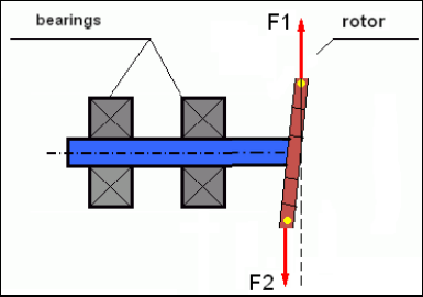
చిత్రం 4. ఊగుతున్న చక్రం యొక్క డైనమిక్ బ్యాలెన్సింగ్
ఇరుకైన రోటర్ షోల్డర్ ఒక చిన్న మొమెంట్ను సృష్టిస్తుంది కాబట్టి, దీనికి పెద్ద ద్రవ్యరాశి గల సవరణ బరువులు అవసరం కావచ్చు. కానీ అదే సమయంలో, సవరణ ద్రవ్యరాశుల నుండి అపకేంద్ర బలాల ప్రభావంతో ఇరుకైన రోటర్ వంగడం వల్ల ఏర్పడే అదనపు “ప్రేరిత అసమతుల్యత” కూడా ఉంటుంది.
ఉదాహరణ చూడండి:
" దృఢమైన రోటర్ బ్యాలెన్సింగ్పై విధానపరమైన సూచనలు" ISO 1940-1:2003 యాంత్రిక కంపనం – స్థిర (దృఢ) స్థితిలో ఉన్న రోటర్లకు బ్యాలెన్స్ నాణ్యత అవసరాలు – భాగం 1: బ్యాలెన్స్ టాలరెన్స్ల నిర్దేశం మరియు ధృవీకరణ
ఇరుకైన ఫ్యాన్ వీల్స్లో ఇది కనిపిస్తుంది, ఇవి పవర్ అసమతుల్యతతో పాటు ఏరోడైనమిక్ అసమతుల్యతను కూడా కలిగి ఉంటాయి. ఏరోడైనమిక్ అసమతుల్యత, అంటే ఏరోడైనమిక్ శక్తి, రోటర్ యొక్క కోణీయ వేగానికి నేరుగా అనుపాతంలో ఉంటుందని గుర్తుంచుకోవడం ముఖ్యం, మరియు దీన్ని భర్తీ చేయడానికి సవరణ ద్రవ్యరాశి యొక్క అపకేంద్ర బలం ఉపయోగించబడుతుంది, ఇది కోణీయ వేగం యొక్క వర్గానికి అనుపాతంలో ఉంటుంది. అందువల్ల, బ్యాలెన్సింగ్ ప్రభావం ఒక నిర్దిష్ట బ్యాలెన్సింగ్ ఫ్రీక్వెన్సీ వద్ద మాత్రమే సంభవించవచ్చు. ఇతర వేగాల వద్ద అదనపు అంతరం ఉంటుంది. ఇదే విషయం విద్యుదయస్కాంత మోటార్లోని విద్యుదయస్కాంత శక్తుల గురించి కూడా చెప్పవచ్చు, ఇవి కూడా కోణీయ వేగానికి అనుపాతంలో ఉంటాయి. మరో మాటలో చెప్పాలంటే, ఏ బ్యాలెన్సింగ్ పద్ధతి ద్వారానైనా మెకానిజం యొక్క కంపనానికి గల అన్ని కారణాలను తొలగించడం అసాధ్యం.
కంపన మూలసిద్ధాంతాలు
కంపనం అనేది చక్రీయ ఉత్తేజిత బలం ప్రభావానికి మెకానిజం డిజైన్ యొక్క ప్రతిస్పందన. ఈ బలం వివిధ స్వభావాలను కలిగి ఉండవచ్చు.
- రోటర్ యొక్క అన్బ్యాలెన్స్ వల్ల ఉత్పత్తి అయ్యే సెంట్రిఫ్యూగల్ ఫోర్స్ "హెవీ పాయింట్"పై ప్రభావం చూపే అసమతుల్య శక్తి. ముఖ్యంగా ఈ శక్తి మరియు దానివల్ల ఏర్పడే వైబ్రేషన్ను రోటర్ బ్యాలెన్సింగ్ ద్వారా తొలగిస్తారు.
- పరస్పర చర్య జరిపే బలాలు, ఇవి “జ్యామితీయ” స్వభావం కలిగి, జతచేయబడే భాగాల తయారీ మరియు ఇన్స్టాలేషన్లో ఏర్పడే దోషాల వల్ల ఉత్పన్నమవుతాయి. ఈ బలాలు, ఉదాహరణకు, షాఫ్ట్ జర్నల్ యొక్క వృత్తాకారం లేకపోవడం వల్ల, గేర్లలో టూత్ ప్రొఫైల్లలోని దోషాల వల్ల, బేరింగ్ ట్రెడ్మిల్ల అలలుగా ఉండటం వల్ల, జతచేయబడిన షాఫ్ట్ల అమరికలోపం వల్ల మొదలైన కారణాల వల్ల ఏర్పడవచ్చు. నెక్ల వృత్తాకారం లేకపోతే, షాఫ్ట్ భ్రమణ కోణాన్ని బట్టి షాఫ్ట్ అక్షం మారుతుంది. ఈ కంపనం రోటర్ వేగంలో వ్యక్తమైనప్పటికీ, దీనిని బ్యాలెన్సింగ్ ద్వారా తొలగించడం దాదాపు అసాధ్యం.
- ఇంపెల్లర్ ఫ్యాన్లు మరియు ఇతర బ్లేడ్ మెకానిజమ్ల భ్రమణం వల్ల ఏర్పడే ఏరోడైనమిక్ బలాలు. హైడ్రాలిక్ పంప్ ఇంపెల్లర్లు, టర్బైన్లు మొదలైన వాటి భ్రమణం వల్ల ఏర్పడే హైడ్రోడైనమిక్ బలాలు.
- ఎలక్ట్రిక్ మెషీన్ల పనితీరు వల్ల ఏర్పడే విద్యుదయస్కాంత శక్తులు, ఉదాహరణకు రోటర్ వైండింగుల అసమరూపత, షార్ట్-సర్క్యూట్ అయిన కాయిళ్ల ఉనికి మొదలైన వాటి వల్ల.
కంపన పరిమాణం (ఉదాహరణకు, దాని ఆంప్లిట్యూడ్ AB) యంత్రంపై పనిచేసే ప్రేరణ బలం Fт యొక్క పరిమాణంపై మాత్రమే కాకుండా, యంత్ర నిర్మాణం యొక్క దృఢత k, దాని ద్రవ్యరాశి m, మరియు డ్యాంపింగ్ గుణకం C పై కూడా ఆధారపడి ఉంటుంది.

కంపనం మరియు బ్యాలెన్స్ యంత్రాలను కొలవడానికి వివిధ రకాల సెన్సార్లను ఉపయోగించవచ్చు, వాటిలో:
- కంపన త్వరణాన్ని (యాక్సిలరోమీటర్లు) మరియు కంపన వేగ సెన్సార్లను కొలవడానికి రూపొందించబడిన పరమ కంపన సెన్సార్లు;
- వైబ్రేషన్ను కొలవడానికి రూపొందించిన ఎడ్డీ-కరెంట్ లేదా కెపాసిటివ్ రిలేటివ్ వైబ్రేషన్ సెన్సర్లు.
కొన్ని సందర్భాల్లో (మెకానిజం నిర్మాణం అనుమతించినప్పుడు) దాని కంపన బరువును పరీక్షించడానికి బల సెన్సార్లను కూడా ఉపయోగించవచ్చు.
ముఖ్యంగా, హార్డ్ బేరింగ్ బ్యాలెన్సింగ్ మెషీన్ల సపోర్ట్ల కంపన బరువును కొలవడానికి ఇవి విస్తృతంగా ఉపయోగించబడతాయి.
అందువల్ల కంపనం అనేది బాహ్య బలాల ప్రభావానికి మెకానిజం చూపే ప్రతిస్పందన. కంపనం యొక్క పరిమాణం మెకానిజంపై పనిచేసే బలం యొక్క పరిమాణంపై మాత్రమే కాకుండా, మెకానిజం యొక్క దృఢత్వంపై కూడా ఆధారపడి ఉంటుంది. ఒకే పరిమాణం గల రెండు బలాలు వేర్వేరు కంపనాలకు దారితీయవచ్చు. దృఢమైన సపోర్ట్ నిర్మాణం గల మెకానిజమ్లలో, చిన్న కంపనం ఉన్నప్పటికీ, బేరింగ్ యూనిట్లు డైనమిక్ బరువుల ద్వారా గణనీయంగా ప్రభావితం కావచ్చు. అందువల్ల, దృఢమైన కాళ్లు గల మెకానిజమ్లను బ్యాలెన్స్ చేసేటప్పుడు బల సెన్సార్లు మరియు కంపన సెన్సార్లు (వైబ్రో-యాక్సిలరోమీటర్లు) రెండింటినీ ఉపయోగిస్తారు. సాపేక్షంగా మృదువైన సపోర్ట్లు గల మెకానిజమ్లలో మాత్రమే కంపన సెన్సార్లను ఉపయోగిస్తారు, అంటే అసమతుల్య అపకేంద్ర బలాల చర్య సపోర్ట్లలో గుర్తించదగిన వైరూప్యం మరియు కంపనానికి దారితీసినప్పుడు. అసమతుల్యత వల్ల ఏర్పడే గణనీయమైన బలాలు గణనీయమైన కంపనానికి దారితీయని సందర్భాల్లో కూడా దృఢమైన సపోర్ట్లలో బల సెన్సార్లను ఉపయోగిస్తారు.
నిర్మాణం యొక్క రెసొనెన్స్
రోటర్లను దృఢమైనవి (రిజిడ్) మరియు వంచదగినవి (ఫ్లెక్సిబుల్) అని రెండు రకాలుగా విభజించవచ్చని మేము ఇంతకుముందు ప్రస్తావించాము. రోటర్ యొక్క దృఢత్వం లేదా వంచదగినతనాన్ని, రోటర్ ఉన్న సపోర్ట్ల (పునాది) యొక్క స్టిఫ్నెస్ లేదా చలనశీలతతో గందరగోళపరచకూడదు. అపకేంద్ర బలాల చర్య కింద దాని వైరూప్యాన్ని (వంపును) విస్మరించగలిగినప్పుడు రోటర్ను దృఢమైనదిగా పరిగణిస్తారు. ఫ్లెక్సిబుల్ రోటర్ యొక్క వైరూప్యం సాపేక్షంగా పెద్దది: దానిని విస్మరించలేము.
ఈ వ్యాసంలో మేము కేవలం rigid rotorల బాలెన్సింగ్ను మాత్రమే అధ్యయనం చేస్తాం. Rigid (వికృతి చెందని) rotor తన వంతుగా rigid లేదా కదులుతున్న (malleable) సపోర్టులపై అమర్చి ఉండవచ్చు. ఈ సపోర్టుల stiffness/గతిశీలత అనేది rotor యొక్క భ్రమణ వేగం మరియు ఫలితంగా వచ్చే centrifugal బలాల పరిమాణంపై ఆధారపడి సాపేక్షంగా ఉంటుందని స్పష్టమవుతోంది. సాంప్రదాయిక సరిహద్దు అంటే rotor సపోర్టులు/పునాదుల స్వేచ్ఛా కంపనాల పౌనఃపున్యం. మెకానికల్ వ్యవస్థలకు, స్వేచ్ఛా కంపనాల ఆకారం మరియు పౌనఃపున్యం మెకానికల్ వ్యవస్థ యొక్క ఘటకాల ద్రవ్యరాశి మరియు స్థితిస్థాపకతపై ఆధారపడి నిర్ణయించబడతాయి. అంటే, natural oscillations పౌనఃపున్యం అనేది మెకానికల్ వ్యవస్థ యొక్క అంతర్గత లక్షణం మరియు బాహ్య బలాలపై ఆధారపడదు. సమతుల్యత స్థితి నుండి వంచబడినప్పుడు, సపోర్టులు స్థితిస్థాపకత కారణంగా తమ సమతుల్యత స్థానానికి తిరిగి రావడానికి ప్రయత్నిస్తాయి. కానీ భారీ rotor యొక్క జడత్వం కారణంగా, ఈ ప్రక్రియ damped oscillations స్వభావాన్ని కలిగి ఉంటుంది. ఈ oscillations అనేవి rotor-support వ్యవస్థ యొక్క స్వంత oscillations. వాటి పౌనఃపున్యం rotor ద్రవ్యరాశి మరియు సపోర్టుల stiffness నిష్పత్తిపై ఆధారపడి ఉంటుంది.

రోటర్ తిరగడం ప్రారంభించి, దాని భ్రమణ పౌనఃపున్యం దాని స్వంత ఓసిలేషన్ల పౌనఃపున్యానికి దగ్గరవుతున్నప్పుడు, కంపన ఆంప్లిట్యూడ్ తీవ్రంగా పెరుగుతుంది, ఇది నిర్మాణం ధ్వంసం కావడానికి కూడా దారితీయవచ్చు.
మెకానికల్ రెసొనెన్స్ అనే దృగ్విషయం ఉంటుంది. రెసొనెన్స్ ప్రాంతంలో, భ్రమణ వేగంలో 100 rpm మార్పు కంపనాన్ని పదిరెట్లు పెంచవచ్చు. ఈ సందర్భంలో (రెసొనెన్స్ ప్రాంతంలో) కంపన ఫేజ్ 180° మారుతుంది.
మెకానిజమ్ యొక్క డిజైన్ సరిగ్గా రూపొందించబడకపోతే, మరియు rotor యొక్క నిర్వహణ వేగం oscillations యొక్క natural frequency కి దగ్గరగా ఉంటే, అనుమతించదగిన దాని కంటే అధిక vibration కారణంగా మెకానిజమ్ నిర్వహణ అసాధ్యమవుతుంది. భ్రమణ వేగంలో స్వల్ప మార్పుతో కూడా పారామీటర్లు నాటకీయంగా మారిపోవడంతో ప్రామాణిక బాలెన్సింగ్ పద్ధతులు కూడా అసాధ్యమవుతాయి. Resonance బాలెన్సింగ్ రంగంలో ప్రత్యేక పద్ధతులు ఉపయోగించబడతాయి కానీ ఈ వ్యాసంలో అవి వివరంగా వివరించబడలేదు. మెకానిజమ్ యొక్క natural oscillations పౌనఃపున్యాన్ని run-out (rotor ఆపివేయబడినప్పుడు) సమయంలో లేదా సిస్టమ్ shock కి సంబంధించిన ప్రతిస్పందన యొక్క తదుపరి spectral analysis తో ఆఘాతం ద్వారా నిర్ణయించవచ్చు. "Balanset-1" ఈ పద్ధతుల ద్వారా మెకానికల్ నిర్మాణాల natural frequencies నిర్ణయించే సామర్థ్యాన్ని అందిస్తుంది.
ఆపరేటింగ్ వేగం రెసొనెన్స్ పౌనఃపున్యం కంటే ఎక్కువగా ఉన్న యంత్రాంగాలకు, అంటే రెసొనెంట్ మోడ్కు మించి పనిచేసేవాటికి, సపోర్ట్లను కదిలేవిగా పరిగణిస్తారు మరియు కొలవడానికి కంపన సెన్సార్లను ఉపయోగిస్తారు, ప్రధానంగా నిర్మాణ భాగాల త్వరణాన్ని కొలిచే కంపన యాక్సిలరోమీటర్లు. హార్డ్ బేరింగ్ మోడ్లో పనిచేసే యంత్రాంగాలకు, సపోర్ట్లను దృఢమైనవిగా పరిగణిస్తారు. ఈ సందర్భంలో, బల సెన్సార్లను ఉపయోగిస్తారు.
మెకానికల్ వ్యవస్థ యొక్క రేఖీయ మరియు అరేఖీయ నమూనాలు
గణిత నమూనాలు (రేఖీయ) దృఢ రోటర్లను బ్యాలెన్స్ చేసేటప్పుడు గణనల కోసం ఉపయోగిస్తారు. నమూనా యొక్క రేఖీయత అంటే ఒక నమూనా మరొకదానిపై నేరుగా అనుపాతంలో (రేఖీయంగా) ఆధారపడి ఉంటుంది. ఉదాహరణకు, రోటర్పై ఉన్న అసమతుల్య ద్రవ్యరాశి రెట్టింపైతే, కంపన విలువ కూడా అనుగుణంగా రెట్టింపవుతుంది. దృఢ రోటర్లకు రేఖీయ నమూనాను ఉపయోగించవచ్చు ఎందుకంటే అటువంటి రోటర్లు వికృతం కావు. ఫ్లెక్సిబుల్ రోటర్లకు రేఖీయ నమూనాను ఉపయోగించడం ఇంకా సాధ్యం కాదు. ఫ్లెక్సిబుల్ రోటర్కు, భ్రమణం సమయంలో బరువు ఉన్న బిందువు యొక్క ద్రవ్యరాశి పెరిగినప్పుడు, అదనపు వికృతి సంభవిస్తుంది మరియు ద్రవ్యరాశితో పాటు, బరువు ఉన్న బిందువు యొక్క వ్యాసార్థం కూడా పెరుగుతుంది. కాబట్టి, ఫ్లెక్సిబుల్ రోటర్కు, కంపనం రెట్టింపు కంటే ఎక్కువ అవుతుంది మరియు సాధారణ గణన పద్ధతులు పనిచేయవు. అలాగే, నమూనా యొక్క రేఖీయత ఉల్లంఘన వారి పెద్ద వికృతుల వద్ద సపోర్ట్ల యొక్క స్థితిస్థాపకతలో మార్పుకు దారితీస్తుంది, ఉదాహరణకు, సపోర్ట్ల చిన్న వికృతుల వద్ద కొన్ని నిర్మాణ భాగాలు పనిచేస్తాయి మరియు పెద్దవి పనిచేసినప్పుడు ఇతర నిర్మాణ భాగాలను చేర్చుతాయి. కాబట్టి, బేస్పై స్థిరపరచబడని యంత్రాంగాలను బ్యాలెన్స్ చేయడం అసాధ్యం, మరియు ఉదాహరణకు, నేలపై సరళంగా ఏర్పాటు చేయబడినవి. గణనీయమైన కంపనాలతో, అసమతుల్యత బలం యంత్రాంగాన్ని నేల నుండి విడదీయవచ్చు, దీనివల్ల వ్యవస్థ యొక్క దృఢత్వ లక్షణాలు గణనీయంగా మారతాయి. ఇంజిన్ కాళ్లను భద్రంగా బంధించాలి, బోల్ట్ ఫాస్టెనర్లను కట్టాలి, వాషర్ల మందం సరిపోయే దృఢత్వాన్ని అందించాలి, మొదలైనవి. పగిలిన బేరింగ్లతో, షాఫ్ట్ యొక్క గణనీయమైన స్థానభ్రంశం మరియు దాని ప్రభావాలు సాధ్యం, ఇది కూడా రేఖీయత ఉల్లంఘనకు మరియు నాణ్యమైన బ్యాలెన్సింగ్ చేయడం అసాధ్యతకు దారితీస్తుంది.
బ్యాలెన్సింగ్ కోసం పద్ధతులు మరియు పరికరాలు
పైన పేర్కొన్నట్లుగా, బ్యాలెన్సింగ్ అనేది ప్రధాన కేంద్ర జడత్వ అక్షాన్ని రోటర్ యొక్క భ్రమణ అక్షంతో కలపే ప్రక్రియ.
నిర్దిష్ట ప్రక్రియను రెండు మార్గాల్లో అమలు చేయవచ్చు.
మొదటి పద్ధతి రోటర్ యొక్క అక్షాలను ప్రాసెస్ చేయడం కలిగి ఉంటుంది, ఇది రోటర్ యొక్క ప్రధాన కేంద్ర జడత్వ అక్షంతో అక్షాల యొక్క విభాగం యొక్క కేంద్రాల గుండా వెళ్లే అక్షం అయ్యేలా చేయబడుతుంది. ఈ సాంకేతికత ఆచరణలో అరుదుగా ఉపయోగించబడుతుంది మరియు ఈ వ్యాసంలో వివరంగా చర్చించబడదు.
రెండవ (అత్యంత సాధారణ) పద్ధతి రోటర్పై సవరణ ద్రవ్యరాశులను కదిలించడం, ఏర్పాటు చేయడం లేదా తొలగించడం కలిగి ఉంటుంది, ఇవి రోటర్ యొక్క జడత్వ అక్షం దాని భ్రమణ అక్షానికి సాధ్యమైనంత దగ్గరగా ఉండేలా ఏర్పాటు చేయబడతాయి.
బ్యాలెన్సింగ్ సమయంలో సవరణ ద్రవ్యరాశులను కదిలించడం, జోడించడం లేదా తొలగించడం బోర్ చేయడం, మిల్లింగ్, సర్ఫేసింగ్, వెల్డింగ్, స్క్రూలను స్క్రూ చేయడం లేదా అన్స్క్రూ చేయడం, లేజర్ బీమ్ లేదా ఎలక్ట్రాన్ బీమ్తో కాల్చడం, విద్యుద్విశ్లేషణ, విద్యుదయస్కాంత వెల్డింగ్ మొదలైనవి సహా వివిధ సాంకేతిక ఆపరేషన్లను ఉపయోగించి చేయవచ్చు.
బ్యాలెన్సింగ్ ప్రక్రియను రెండు మార్గాల్లో నిర్వహించవచ్చు:
- బాలెన్స్ చేయబడిన rotorల అసెంబ్లీ (వాటి స్వంత bearingsలో);
- బాలెన్సింగ్ మెషీన్లపై rotorల బాలెన్సింగ్.
వారి స్వంత బేరింగ్లలో రోటర్లను బ్యాలెన్స్ చేయడానికి మేము సాధారణంగా ప్రత్యేక బ్యాలెన్సింగ్ పరికరాలను (కిట్లు) ఉపయోగిస్తాము, ఇది బ్యాలెన్స్ చేయబడిన రోటర్ యొక్క కంపనాన్ని దాని భ్రమణ వేగంలో వెక్టర్ రూపంలో కొలవడానికి అనుమతిస్తుంది, అంటే కంపనం యొక్క ఆంప్లిట్యూడ్ మరియు ఫేజ్ రెండింటినీ కొలవడం.
ప్రస్తుతం, ఈ పరికరాలు మైక్రోప్రాసెసర్ సాంకేతికత ఆధారంగా తయారు చేయబడతాయి మరియు (కంపన కొలత మరియు విశ్లేషణతో పాటు) రోటర్పై ఏర్పాటు చేయబడాలి మరియు దాని అసమతుల్యతను పరిహరించాలి అనే సవరణ బరువుల పారామితులను ఆటోమేటెడ్ గణనను అందిస్తాయి.
ఈ పరికరాలలో ఇవి ఉంటాయి:
- – కంప్యూటర్ లేదా ఇండస్ట్రియల్ కంట్రోలర్ ఆధారంగా తయారు చేయబడిన కొలత మరియు కంప్యూటింగ్ యూనిట్;
- రెండు (లేదా అంతకంటే ఎక్కువ) కంపన సెన్సార్లు;
- ఫేజ్ కోణ సెన్సార్;
- సౌకర్యంలో సెన్సార్లు అమర్చడానికి పరికరాలు;
- ఒకటి, రెండు లేదా అంతకంటే ఎక్కువ correction planes లో rotor అన్బాలెన్స్ పారామీటర్ల పూర్తి కొలత చక్రం నిర్వహించడానికి రూపొందించబడిన ప్రత్యేక సాఫ్ట్వేర్.
బ్యాలెన్సింగ్ మెషీన్లపై రోటర్లను బ్యాలెన్స్ చేయడానికి ప్రత్యేక బ్యాలెన్సింగ్ పరికరం (మెషీన్ యొక్క కొలత వ్యవస్థ) తో పాటు, రోటర్ను సపోర్ట్లపై ఏర్పాటు చేయడానికి మరియు స్థిరమైన వేగంలో దాని భ్రమణాన్ని నిర్ధారించడానికి రూపొందించబడిన “అన్వైండింగ్ మెకానిజం” ఉండాలి.
ప్రస్తుతం, అత్యంత సాధారణ బ్యాలెన్సింగ్ మెషీన్లు రెండు రకాలుగా ఉన్నాయి:
- over-resonant (వశ్యమైన సపోర్టులతో);
- hard bearing (rigid సపోర్టులతో).
ఓవర్-రెసొనెంట్ మెషీన్లు సాపేక్షంగా మృదువైన సపోర్ట్లను కలిగి ఉంటాయి, ఉదాహరణకు ఫ్లాట్ స్ప్రింగ్ల ఆధారంగా తయారు చేయబడతాయి.
ఈ సపోర్ట్ల యొక్క సహజ డోలన పౌనఃపున్యం సాధారణంగా వాటిపై మౌంట్ చేయబడిన బ్యాలెన్స్ చేయబడిన రోటర్ యొక్క వేగం కంటే 2-3 రెట్లు తక్కువగా ఉంటుంది.
రెసొనెంట్ మెషీన్ యొక్క సపోర్ట్ల యొక్క కంపనాన్ని కొలవడానికి కంపన సెన్సార్లు (యాక్సిలరేషన్ సెన్సార్లు, కంపన వేగ సెన్సార్లు మొదలైనవి) సాధారణంగా ఉపయోగించబడతాయి.
హార్డ్ బేరింగ్ బ్యాలెన్సింగ్ మెషీన్లలో సాపేక్షంగా దృఢమైన సపోర్ట్లు ఉపయోగించబడతాయి, వాటి సహజ డోలన పౌనఃపున్యాలు బ్యాలెన్స్ చేయబడిన రోటర్ యొక్క వేగం కంటే 2-3 రెట్లు ఎక్కువగా ఉండాలి.
మెషీన్ యొక్క సపోర్ట్లపై కంపన బరువును కొలవడానికి బల సెన్సార్లు సాధారణంగా ఉపయోగించబడతాయి.
హార్డ్ బేరింగ్ బ్యాలెన్సింగ్ మెషీన్ల యొక్క ప్రయోజనం ఏమిటంటే, అవి సాపేక్షంగా తక్కువ రోటర్ వేగాల వద్ద (400-500 rpm వరకు) బ్యాలెన్స్ చేయబడవచ్చు, ఇది మెషీన్ యొక్క డిజైన్ మరియు దాని పునాదిని గణనీయంగా సులభతరం చేస్తుంది, అలాగే బ్యాలెన్సింగ్ యొక్క ఉత్పాదకత మరియు భద్రతను పెంచుతుంది.
బ్యాలెన్సింగ్ పద్ధతి
⚠️ బ్యాలెన్సింగ్ రోటర్ ద్రవ్యరాశి పంపిణీ యొక్క అసమరూపత వల్ల కలిగే కంపనాన్ని మాత్రమే తొలగిస్తుంది. ఇతర రకాల కంపనాలను బ్యాలెన్సింగ్ ద్వారా తొలగించలేరు!
బ్యాలెన్సింగ్ సాంకేతికంగా సేవలో ఉన్న యంత్రాంగాలకు లోబడి ఉంటుంది, వాటి డిజైన్ పనిచేసే వేగంలో రెసొనెన్స్ల లేమిని నిర్ధారిస్తుంది, పునాదిపై భద్రంగా స్థిరపరచబడింది, సేవలో ఉన్న బేరింగ్లలో ఏర్పాటు చేయబడింది.
🚫 దోషపూరిత యంత్రాంగం మరమ్మతుకు లోబడి ఉంటుంది, మరియు ఆ తర్వాత మాత్రమే – బ్యాలెన్సింగ్కు. లేకపోతే, నాణ్యమైన బ్యాలెన్సింగ్ అసాధ్యం.
బ్యాలెన్సింగ్ మరమ్మతుకు ప్రత్యామ్నాయం కాదు!
బ్యాలెన్సింగ్ యొక్క ప్రధాన లక్ష్యం సెంట్రీఫ్యూగల్ బలాల ద్వారా బ్యాలెన్స్ చేయబడే పరిహార బరువుల యొక్క ద్రవ్యరాశి మరియు స్థానం (కోణం)ను కనుగొనడం.
పైన పేర్కొన్నట్లుగా, దృఢ రోటర్లకు సాధారణంగా రెండు పరిహార బరువులను ఏర్పాటు చేయడం అవసరం మరియు సరిపోతుంది. ఇది స్థిర మరియు డైనమిక్ రోటర్ అసమతుల్యత రెండింటినీ తొలగిస్తుంది. బ్యాలెన్సింగ్ సమయంలో కంపన కొలత యొక్క సాధారణ యోజన ఈ క్రింది విధంగా ఉంటుంది:
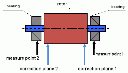
చిత్రం.5 డైనమిక్ బ్యాలెన్సింగ్ – సవరణ తలాలు మరియు కొలత బిందువులు
కంపన సెన్సార్లు బేరింగ్ సపోర్ట్లపై బిందువులు 1 మరియు 2 వద్ద ఏర్పాటు చేయబడతాయి. వేగ గుర్తు నేరుగా రోటర్పై స్థిరపరచబడుతుంది, ప్రతిబింబిత టేప్ సాధారణంగా అంటించబడుతుంది. వేగ గుర్తు రోటర్ యొక్క వేగం మరియు కంపన సిగ్నల్ యొక్క ఫేజ్ను నిర్ణయించడానికి లేజర్ టాకోమీటర్ ద్వారా ఉపయోగించబడుతుంది.
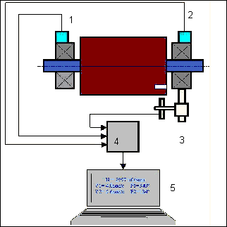
చిత్రం 6. Balanset-1 ఉపయోగించి రెండు planes లో బాలెన్సింగ్ సమయంలో సెన్సార్ల అమరిక
1,2-కంపన సెన్సార్లు, 3-ఫేజ్, 4- USB కొలత యూనిట్, 5-లాప్టాప్
అత్యధిక సందర్భాలలో, డైనమిక్ బ్యాలెన్సింగ్ మూడు స్టార్ట్ల పద్ధతి ద్వారా నిర్వహించబడుతుంది. ఈ పద్ధతి ఇప్పటికే తెలిసిన ద్రవ్యరాశి యొక్క పరీక్ష బరువులు 1 మరియు 2 తలాలలో శ్రేణిలో రోటర్పై ఏర్పాటు చేయబడతాయి అనే వాస్తవంపై ఆధారపడి ఉంటుంది; కాబట్టి కంపన పారామితులలో మార్పుల ఫలితాల ఆధారంగా బ్యాలెన్సింగ్ బరువుల యొక్క ద్రవ్యరాశులు మరియు ఏర్పాటు స్థానం గణించబడతాయి.
బరువు అమర్చే స్థానాన్ని correction plane అంటారు. సాధారణంగా, correction planesను rotor అమర్చబడిన bearing సపోర్టుల ప్రాంతంలో ఎంపిక చేస్తారు.
మొదటి స్టార్ట్లో ప్రారంభ కంపనం కొలవబడుతుంది. తర్వాత, తెలిసిన ద్రవ్యరాశి కలిగిన ట్రయల్ వెయిట్ను రోటర్పై ఒక సపోర్ట్కు దగ్గరగా అమర్చుతారు. తర్వాత రెండవ స్టార్ట్ నిర్వహించబడుతుంది, మరియు ట్రయల్ వెయిట్ అమరిక కారణంగా మారవలసిన కంపన పారామీటర్లను కొలుస్తాము. తర్వాత మొదటి ప్లేన్లోని ట్రయల్ వెయిట్ను తొలగించి రెండవ ప్లేన్లో అమర్చుతారు. మూడవ స్టార్ట్-అప్ నిర్వహించబడుతుంది మరియు కంపన పారామీటర్లు కొలవబడతాయి. ట్రయల్ వెయిట్ తొలగించిన తర్వాత, ప్రోగ్రామ్ స్వయంచాలకంగా బ్యాలెన్సింగ్ వెయిట్ల అమరికకు సంబంధించిన ద్రవ్యరాశి మరియు స్థానాన్ని (కోణాలు) లెక్కిస్తుంది.
పరీక్ష బరువులను సెట్ చేయడంలో ఉద్దేశ్యం వ్యవస్థ అసమతుల్యత మార్పుకు ఎలా స్పందిస్తుందో నిర్ణయించడం. మేము నమూనా బరువుల యొక్క ద్రవ్యరాశులు మరియు స్థానాన్ని తెలుసుకున్నప్పుడు, ప్రోగ్రామ్ తెలిసిన అసమతుల్యతను ప్రవేశపెట్టడం కంపన పారామితులను ఎలా ప్రభావితం చేస్తుందో చూపించే ప్రభావ గుణకాలను గణించవచ్చు. ప్రభావ గుణకాలు యాంత్రిక వ్యవస్థ యొక్క లక్షణాలు మరియు సపోర్ట్ల యొక్క దృఢత్వం మరియు రోటర్-సపోర్ట్ వ్యవస్థ యొక్క ద్రవ్యరాశి (జడత్వం)పై ఆధారపడి ఉంటాయి.
అదే రకమైన డిజైన్ యొక్క అదే రకమైన యంత్రాంగాలకు, ప్రభావ గుణకాలు సారూప్యంగా ఉంటాయి. మీరు వాటిని మీ కంప్యూటర్ మెమరీలో సేవ్ చేయవచ్చు మరియు పరీక్ష రన్లను నిర్వహించకుండా అదే రకమైన యంత్రాంగాలను బ్యాలెన్స్ చేయడానికి తర్వాత వాటిని ఉపయోగించవచ్చు, ఇది బ్యాలెన్సింగ్ యొక్క పనితీరును గణనీయంగా మెరుగుపరుస్తుంది. పరీక్ష బరువుల ద్రవ్యరాశి పరీక్ష బరువులను ఏర్పాటు చేసినప్పుడు కంపన పారామితులు గణనీయంగా మారేలా ఎంపిక చేయబడాలి అని మేము కూడా గమనించాలి. లేకపోతే, ప్రభావ గుణకాలను గణించడంలో దోషం పెరుగుతుంది మరియు బ్యాలెన్సింగ్ నాణ్యత దెబ్బతింటుంది.
Balanset-1 పరికర మార్గదర్శిని బ్యాలెన్స్ చేయబడిన రోటర్ యొక్క ద్రవ్యరాశి మరియు భ్రమణ వేగాన్ని బట్టి ట్రయల్ వెయిట్ ద్రవ్యరాశిని సుమారుగా నిర్ణయించగలిగే ఒక సూత్రాన్ని అందిస్తుంది. Fig. 1 నుండి మీరు అర్థం చేసుకోగలిగినట్లుగా, సెంట్రిఫ్యూగల్ బలం రేడియల్ దిశలో, అంటే రోటర్ అక్షానికి లంబంగా పని చేస్తుంది. అందువల్ల, వైబ్రేషన్ సెన్సార్లు వాటి సెన్సిటివిటీ అక్షం కూడా రేడియల్ దిశలో ఉండేలా అమర్చాలి. సాధారణంగా అడ్డదిశలో ఫౌండేషన్ యొక్క దృఢత్వం తక్కువగా ఉంటుంది, కాబట్టి అడ్డదిశలో కంపనం అధికంగా ఉంటుంది. అందువల్ల, సెన్సార్ల సెన్సిటివిటీని పెంచడానికి వాటిని వాటి సెన్సిటివిటీ అక్షం కూడా అడ్డదిశలో ఉండేలా అమర్చాలి. అయినప్పటికీ ఇందులో పెద్ద తేడా లేదు. రేడియల్ దిశలో కంపనంతో పాటు, రోటర్ భ్రమణ అక్షం వెంబడి యాక్సియల్ దిశలో కంపనాన్ని కూడా నియంత్రించాల్సి ఉంటుంది. ఈ కంపనం సాధారణంగా అన్బ్యాలెన్స్ వల్ల కాదు, కాప్లింగ్ ద్వారా అనుసంధానించబడిన షాఫ్ట్ల అమరికలోపం మరియు తప్పుదారి పట్టించడం వంటి ఇతర కారణాల వల్ల వస్తుంది. ఈ కంపనం బ్యాలెన్సింగ్ ద్వారా తొలగించబడదు; ఈ సందర్భంలో అమరిక సరిచేయడం అవసరం. ఆచరణలో, సాధారణంగా ఇటువంటి మెకానిజమ్లలో రోటర్ అన్బ్యాలెన్స్ మరియు షాఫ్ట్ల తప్పుదారి పట్టించడం రెండూ ఉంటాయి, ఇవి కంపనాన్ని తొలగించే పనిని చాలా క్లిష్టంగా చేస్తాయి. అటువంటి సందర్భాలలో, మీరు ముందుగా అమరికను సరిచేసి, తర్వాత మెకానిజమ్ను బ్యాలెన్స్ చేయాలి. (అయినప్పటికీ బలమైన టార్క్ అన్బ్యాలెన్స్ ఉన్నప్పుడు, ఫౌండేషన్ నిర్మాణం "మెలితిరగడం" వల్ల యాక్సియల్ దిశలో కూడా కంపనం వస్తుంది).
కొలత ఖచ్చితత్వం మరియు లోపాల విశ్లేషణ
వృత్తిపరమైన బ్యాలెన్సింగ్ కార్యకలాపాల కోసం కొలత ఖచ్చితత్వాన్ని అర్థం చేసుకోవడం అత్యంత ముఖ్యమైనది. Balanset-1A కింది కొలత నిర్దుష్టతను అందిస్తుంది:
| పరామితి | ఖచ్చితత్వ సూత్రం | ఉదాహరణ (సాధారణ విలువల కోసం) |
|---|---|---|
| RMS కంపన వేగం | ±(0.1 + 0.1×Vకొలిచిన) mm/sec | 5 mm/sec కోసం: ±0.6 mm/sec 10 mm/sec కోసం: ±1.1 mm/sec |
| భ్రమణ పౌనఃపున్యం | ±(1 + 0.005×Nకొలిచిన) rpm | 1000 rpm కోసం: ±6 rpm 3000 rpm కోసం: ±16 rpm |
| దశ కొలత | ±1° | అన్ని వేగాల వద్ద స్థిరమైన అచ్చుదనం |
⚠️ ఖచ్చితమైన బ్యాలెన్సింగ్కు కీలకమైనది
- !ట్రయల్ వెయిట్ వల్ల వ్యాప్తిలో >20-30% మార్పు కలగాలి మరియు/లేదా >20-30° ఫేజ్ మార్పు
- !మార్పులు చిన్నవిగా ఉంటే, కొలత లోపాలు గణనీయంగా పెరుగుతాయి
- !కొలతల మధ్య కంపన యాంప్లిట్యూడ్ మరియు ఫేజ్ స్థిరత్వం 10-15% కంటే ఎక్కువ మారకూడదు
- !వ్యత్యాసం 15% మించిపోతే, రెసొనెన్స్ పరిస్థితులు లేదా మెకానికల్ సమస్యలను తనిఖీ చేయండి
బ్యాలెన్సింగ్ మెకానిజమ్ల నాణ్యతను అంచనా వేయడానికి ప్రమాణాలు
రోటర్ (మెకానిజం) బ్యాలెన్సింగ్ నాణ్యతను రెండు మార్గాల్లో అంచనా వేయవచ్చు. మొదటి పద్ధతిలో, బ్యాలెన్సింగ్ సమయంలో నిర్ణయించబడిన శేష అసమతుల్యత విలువను శేష అసమతుల్యత యొక్క టాలరెన్స్తో పోల్చడం ఉంటుంది. ప్రామాణికంగా ISO 21940-11 «Mechanical vibration – Rotor balancing – Part 11: Procedures and tolerances for rotors with rigid behaviour» (గతంలో ISO 1940-1 అని పిలిచేవారు).
అయినప్పటికీ, ఈ సహనాల అమలు మెకానిజం యొక్క కార్యాచరణ విశ్వసనీయతను పూర్తిగా హామీ ఇవ్వలేదు, ఎందుకంటే ఇది కనీస vibration స్థాయి సాధనతో సంబంధం కలిగి ఉంటుంది. ఇది ఈ వాస్తవం వల్ల: మెకానిజం యొక్క vibration దాని rotor యొక్క residual unbalance తో సంబంధం ఉన్న బలం మొత్తంపై మాత్రమే కాకుండా, నిర్మాణ అంశాల దృఢత్వం K, దాని ద్రవ్యరాశి M, అవమందన గుణకం మరియు వేగం సహా అనేక ఇతర పారామీటర్లపై కూడా ఆధారపడి ఉంటుంది. అందువల్ల, మెకానిజం యొక్క డైనమిక్ నాణ్యతలను అంచనా వేయడానికి (దాని సమతుల్యత నాణ్యతను కూడా పరిగణనలో తీసుకుని) కొన్ని సందర్భాలలో మెకానిజం యొక్క residual vibration స్థాయిని అంచనా వేయాలని సిఫార్సు చేయబడింది, ఇది అనేక ప్రమాణాల ద్వారా నియంత్రించబడుతుంది.
మెకానిజం యొక్క అనుమతించదగిన కంపన స్థాయిలను నియంత్రించే అత్యంత సాధారణ ప్రామాణికం ISO 10816-3:2009 Preview Mechanical vibration — Evaluation of machine vibration by measurements on non-rotating parts — Part 3: Industrial machines with nominal power above 15 kW and nominal speeds between 120 r/min and 15 000 r/min when measured in situ.»
దీని సహాయంతో, వాటి విద్యుత్ డ్రైవ్ యొక్క శక్తిని పరిగణనలోకి తీసుకుని, అన్ని రకాల యంత్రాలపై టాలరెన్స్ను సెట్ చేయవచ్చు.
ఈ సార్వత్రిక ప్రామాణికంతో పాటు, నిర్దిష్ట రకాల మెకానిజం కోసం అభివృద్ధి చేయబడిన అనేక ప్రత్యేక ప్రామాణికాలు ఉన్నాయి. ఉదాహరణకు,
- ISO 14694:2003 "పారిశ్రామిక పంకాలు – సమతుల్యత నాణ్యత మరియు vibration స్థాయిల వివరణలు"
- ISO 7919-1-2002 “Vibration of machines without reciprocating motion. Measurements on rotating shafts and evaluation criteria. General guidance.»
🛡️ EU సమ్మతి కోసం ముఖ్యమైన భద్రతా పరిగణనలు
- !రిస్క్ అసెస్మెంట్ అవసరం: బ్యాలెన్సింగ్ కార్యకలాపాలకు ముందు EN ISO 12100 ప్రమాద అంచనా నిర్వహించాలి
- !అర్హత కలిగిన సిబ్బంది: శిక్షణ పొందిన మరియు సర్టిఫికేట్ పొందిన సిబ్బంది మాత్రమే balancing కార్యకలాపాలు నిర్వహించాలి
- !వ్యక్తిగత రక్షణ సాధనాలు: EN 166 (కంటి రక్షణ) మరియు EN 352 (వినికిడి రక్షణ) ప్రకారం తగిన PPE ఎల్లప్పుడూ ఉపయోగించండి
- !అత్యవసర విధానాలు: స్పష్టమైన అత్యవసర షట్డౌన్ విధానాలను ఏర్పాటు చేయండి మరియు అన్ని ఆపరేటర్లు వాటిపై అవగాహన కలిగి ఉండేలా చూసుకోండి
- !డాక్యుమెంటేషన్: ట్రేస్ చేయగలిగేలా మరియు సమ్మతి కోసం అన్ని balancing కార్యకలాపాల వివరణాత్మక రికార్డులను నిర్వహించండి
EU అనుపాలన మరియు భద్రతా సమాచారం
అనుగుణ్య ప్రకటన
Balanset-1A పోర్టబుల్ బ్యాలెన్సర్ కింది యూరోపియన్ యూనియన్ నిర్దేశాలు మరియు ప్రమాణాలను పాటిస్తుంది:
| EU డైరెక్టివ్/ప్రమాణం | సమ్మతి వివరాలు | భద్రతా అవసరాలు |
|---|---|---|
| యంత్రాల నిర్దేశం 2006/42/EC | యంత్రాలు మరియు భద్రతా భాగాల కోసం భద్రతా అవసరాలు | రిస్క్ అంచనా, భద్రతా సూచనలు, CE మార్కింగ్ |
| EMC నిర్దేశం 2014/30/EU | విద్యుదయస్కాంత అనుకూలత అవసరాలు | విద్యుదయస్కాంత అడ్డంకులకు నిరోధకత |
| RoHS డైరెక్టివ్ 2011/65/EU | హానికారక పదార్థాల నిషేధం | సీసం-రహిత, పాదరసం-రహిత, కాడ్మియం-రహిత భాగాలు |
| WEEE నిర్దేశం 2012/19/EU | వ్యర్థ విద్యుత్ మరియు ఎలక్ట్రానిక్ పరికరాలు | సరైన పారవేయడం మరియు రీసైకిలింగ్ విధానాలు |
| EN ISO 12100:2010 | యంత్రాల భద్రత - డిజైన్ కోసం సాధారణ సూత్రాలు | ప్రమాద మూల్యాంకనం మరియు ప్రమాద తగ్గింపు |
| EN 60825-1:2014 | లేజర్ ఉత్పత్తుల భద్రత - భాగం 1 | క్లాస్ 2 లేజర్ భద్రతా అవసరాలు |
| EN ISO 14120:2015 | రక్షణ కవచాలు - సాధారణ అవసరాలు | తిరుగుతున్న యంత్రాల ప్రమాదాల నుండి రక్షణ |
విద్యుత్ భద్రతా ప్రమాణాలు
- ✓EN 61010-1: కొలత, నియంత్రణ మరియు ప్రయోగశాల వినియోగం కోసం విద్యుత్ పరికరాల భద్రతా అవసరాలు
- ✓EN 60950-1: ఇన్ఫర్మేషన్ టెక్నాలజీ పరికరాల భద్రత (USB ద్వారా నడిచే పరికరం)
- ✓IEC 61000 సిరీస్: విద్యుదయస్కాంత అనుకూలత ప్రమాణాలు
- ✓ఆపరేటింగ్ వోల్టేజ్: USB ద్వారా 5V DC (అత్యంత తక్కువ వోల్టేజ్)
- ✓విద్యుత్ వినియోగం: < 2.5W
- ✓రక్షణ తరగతి: IP54 (ధూళి-రక్షితం; స్ప్లాష్-వాటర్ నిరోధకత)
తిరుగుతున్న పరికరాల భద్రత
⚠️ తప్పనిసరి భద్రతా విధానాలు (EN ISO 12100)
హెచ్చరిక: తిరుగుతున్న యంత్రాలతో పని చేసేటప్పుడు, కింది భద్రతా అవసరాలు పాటించండి:
- !EN ISO 14118: అనుకోని స్టార్ట్-అప్ నివారణ - సెన్సర్ అమర్చే ముందు lockout/tagout విధానాలు ఉపయోగించండి
- !EN ISO 14120: అన్ని తిరుగుతున్న పరికరాలు సరిగ్గా రక్షిత కవచంతో అమర్చబడి ఉన్నాయని నిర్ధారించుకోండి
- !EN ISO 13857: తిరుగుతున్న భాగాల నుండి కనీస సురక్షిత దూరాన్ని నిర్వహించండి (శరీరానికి 500mm, వేళ్లకు 120mm)
- !వ్యక్తిగత రక్షణ సాధనాలు: EN 166 ప్రకారం భద్రతా కళ్లద్దాలు ధరించండి, EN 352 ప్రకారం వినికిడి రక్షణ ధరించండి మరియు వదులుగా ఉన్న దుస్తులు నివారించండి
- !తిరుగుతున్న యంత్రాలు కదులుతున్నప్పుడు ఎప్పుడూ సెన్సర్లు లేదా trial weights అమర్చవద్దు
- !సెన్సర్ అమర్చే ముందు యంత్రం పూర్తిగా ఆగి సురక్షితంగా ఉందని నిర్ధారించుకోండి
- !అత్యవసర స్టాప్: ఆపరేటర్ స్థానం నుండి 3 మీటర్ల లోపల అందుబాటులో ఉండాలి
- !అర్హత పొందిన మరియు సర్టిఫికేట్ పొందిన సిబ్బంది మాత్రమే balancing కార్యకలాపాలు నిర్వహించాలి
లేజర్ భద్రతా వర్గీకరణ
🔴 క్లాస్ 2 లేజర్ పరికరం (EN 60825-1:2014)
- తరంగదైర్ఘ్యం: 650 nm (ఎరుపు దృశ్యమాన కాంతి)
- గరిష్ట అవుట్పుట్ శక్తి: < 1 mW
- బీమ్ వ్యాసం: 100mm దూరంలో 3-5 mm
- డైవర్జెన్స్: < 1.5 mrad
- భద్రతా వర్గీకరణ: క్షణికావేశ బహిర్గతానికి కంటికి సురక్షితం (< 0.25 sec)
- అవసరమైన లేబులింగ్: "లేజర్ రేడియేషన్ - పుంజంలోకి నేరుగా చూడకండి - క్లాస్ 2 లేజర్ ఉత్పత్తి"
- యాక్సెస్ తరగతి: నిర్బంధం లేనిది (సాధారణ ప్రవేశం అనుమతించబడుతుంది)
లేజర్ భద్రతా విధానాలు:
- లేజర్ పుంజంలోకి ఉద్దేశపూర్వకంగా చూడకండి
- లేజర్ను వ్యక్తులపైకి, వాహనాలపైకి లేదా విమానాలపైకి గురిపెట్టకండి
- ఆప్టికల్ పరికరాలతో (టెలిస్కోప్లు, బైనాక్యులర్లు) లేజర్ కిరణాన్ని చూడడం నివారించండి
- మెరిసే ఉపరితలాల నుండి specular reflections గురించి అవగాహన కలిగి ఉండండి
- ఉపయోగంలో లేనప్పుడు లేజర్ ఆపివేయండి
- కంటికి గురైన సంఘటనలను వెంటనే నివేదించండి
- దీర్ఘకాల బహిర్గతానికి లేజర్ భద్రతా కళ్లద్దాలు ఉపయోగించండి (650nm వద్ద OD 2+)
కొలత ఖచ్చితత్వం మరియు అంశాంకన
| పరామితి | ఖచ్చితత్వం | అంశాంకన పౌనఃపున్యం |
|---|---|---|
| కంపన వ్యాప్తి | రీడింగ్లో ±5% | ప్రతి సంవత్సరం లేదా 1000 గంటల తర్వాత |
| దశ కొలత | ±1° | వార్షికంగా |
| భ్రమణ వేగం | రీడింగ్లో ±0.1% | వార్షికంగా |
| సెన్సార్ సున్నితత్వం | 13 mV/(mm/s) ±10% | సెన్సార్లు మార్చేటప్పుడు |
పర్యావరణ అనుపాలన
- ✓పని చేసే వాతావరణం: 5°C నుండి 50°C వరకు, < 85% RH కందెన లేకుండా
- ✓నిల్వ పర్యావరణం: -20°C నుండి 70°C వరకు, < 95% RH సంగ్రహణ లేకుండా
- ✓ఎత్తు: సముద్ర మట్టానికి 2000m వరకు
- ✓కంపన నిరోధకత: IEC 60068-2-6 (10-500 Hz, 2g త్వరణం)
- ✓షాక్ నిరోధకత: IEC 60068-2-27 (15g, 11ms వ్యవధి)
- ✓IP రేటింగ్: IP54 (ధూళి-రక్షితం; స్ప్లాష్-వాటర్ నిరోధకత)
పరిచాలన అవసరాలు
- ✓EU ప్రమాణాల ప్రకారం యంత్రసామగ్రి భద్రతలో ఆపరేటర్లు శిక్షణ పొందాలి
- ✓ఉపయోగించే ముందు EN ISO 12100 ప్రకారం రిస్క్ అసెస్మెంట్ అవసరం
- ✓తయారీదారు నిర్దేశాల ప్రకారం పరికరాలను నిర్వహించండి
- ✓ఏదైనా భద్రతా సంఘటన లేదా పరికర లోపాన్ని వెంటనే నివేదించండి
- ✓ట్రేసబిలిటీ కోసం అన్ని బ్యాలెన్సింగ్ కార్యకలాపాల వివరణాత్మక రికార్డులను నిర్వహించండి
డాక్యుమెంటేషన్ అవసరాలు
EU అనుపాలన కోసం, కింది డాక్యుమెంటేషన్ నిర్వహించండి:
- ✓EN ISO 12100 ప్రకారం రిస్క్ అసెస్మెంట్ డాక్యుమెంటేషన్
- ✓ఆపరేటర్ శిక్షణ రికార్డులు మరియు సర్టిఫికేషన్లు
- ✓పరికర కాలిబ్రేషన్ మరియు నిర్వహణ లాగ్లు
- ✓తేదీలు, ఆపరేటర్లు మరియు ఫలితాలతో బ్యాలెన్సింగ్ కార్యకలాపాల రికార్డులు
- ✓భద్రత సంఘటన నివేదికలు మరియు దిద్దుబాటు చర్యలు
- ✓పరికర మార్పు లేదా మరమ్మత్తు డాక్యుమెంటేషన్
సాంకేతిక మద్దతు మరియు సేవ
సాంకేతిక మద్దతు, కాలిబ్రేషన్ సేవలు మరియు విడిభాగాల కోసం:
- ✓తయారీదారు: Vibromera
- ✓స్థానం: నార్వా, ఎస్టోనియా (EU)
- ✓వెబ్సైట్: https://vibromera.eu
- ✓మద్దతు భాషలు: అన్ని ప్రధాన భాషలు. వచన-ఆధారిత సంప్రదింపులు అందుబాటులో ఉన్నాయి.
- ✓సేవా పరిధి: ప్రపంచవ్యాప్త షిప్పింగ్ అందుబాటులో ఉంది
- ✓వారంటీ: కొనుగోలు తేదీ నుండి 12 నెలలు
- ✓క్యాలిబ్రేషన్ సేవ: అధికృత సేవా కేంద్రాల ద్వారా అందుబాటులో ఉంది

