Centrifuge Balancing: On-Site Procedure for Industrial Centrifuges
A field technician's reference for two-plane dynamic balancing of decanters, disc-stacks, basket, and tubular centrifuges — without removing the rotor from the machine.
Why Centrifuge Imbalance Costs More Than You Think
Centrifuges operate at speeds that most industrial machinery never reaches. A decanter running at 3,000 RPM makes 50 revolutions per second. A disc-stack separator at 6,000 RPM — 100 revolutions per second. At these speeds, even grams of imbalance generate forces measured in kilonewtons.
The physics is unforgiving: centrifugal force grows with the square of the speed. An imbalance that produces 50 N of force at 3,000 RPM creates 200 N at 6,000 RPM — four times more, from the same few grams. Every missing chip of metal, every uneven deposit on the bowl wall, every slight asymmetry in the scroll — all of it gets amplified at speed.
Here's what that translates to in practice:
Unbalanced centrifuges consume bearings 3–5× faster. One set: €800–3,000+.
Wobbling rotors reduce product purity and increase solids in the centrate.
Exceeds workplace limits. Audible throughout the process building.
Bearing replacement + lost production + emergency procurement + overtime labor.
Beyond the direct costs, there's a subtler problem. Centrifuges in pharmaceutical and food processing must meet stringent quality standards. A vibrating centrifuge produces inconsistent separation — batches that should pass QC don't. In pharma, a failed batch isn't just waste; it's a compliance event, a root-cause investigation, and potentially a regulatory flag.
A single unplanned centrifuge shutdown in a continuous chemical process can cost €15,000–50,000 in lost production, depending on the product. Balancing the rotor takes 1–2 hours and costs a fraction of that. The economics aren't subtle.
Centrifuge Types and Their Balancing Differences
The two-plane trial weight method applies to all centrifuge types. But access points, correction plane locations, and typical imbalance sources differ considerably. Knowing the machine type before you arrive saves time and avoids surprises.
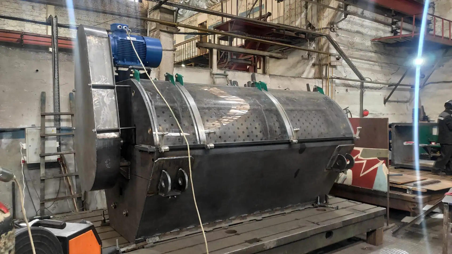
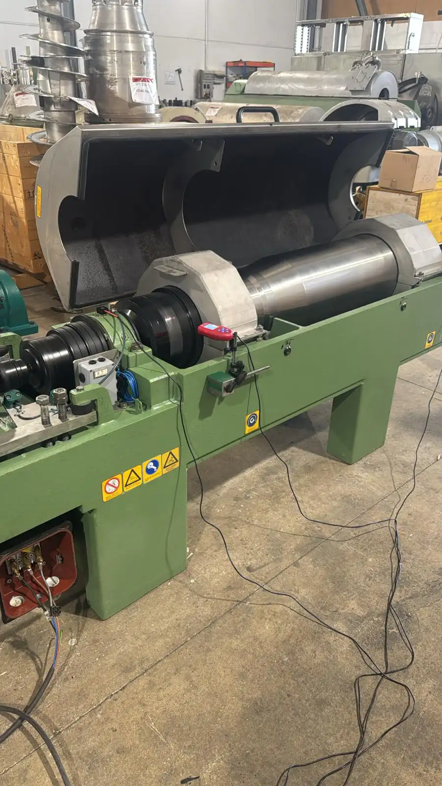
Decanter centrifuges
Long, cylindrical bowl with an internal scroll conveyor. Two separate rotors (bowl and scroll) that must be balanced independently. Imbalance typically arises from wear on the scroll flights, uneven solids buildup, or slight bowl distortion from thermal cycling. Correction planes are on the end flanges or hub faces.
Disc-stack separators
High-speed vertical machines with a stack of conical discs. Extremely sensitive to imbalance due to high RPM. Common sources: missing or shifted disc, uneven sludge pockets, nozzle wear. Correction is usually done on the bowl top and bottom. Access requires removing the cover — plan for this.
Basket (peeler) centrifuges
Perforated basket for filtration. The most common imbalance source is uneven cake distribution — product isn't fed symmetrically, so more mass accumulates on one side. Balancing the empty basket is only half the job; the feed distribution should also be addressed. Corrections go on the basket rim or hub.
Tubular centrifuges
Ultra-high-speed, small-diameter bowls. Extremely tight balance tolerances (often G1.0 or better). Imbalance from even milligrams is significant. These are usually shop-balanced, but in-situ trim balancing after reinstallation improves results. Use very small trial weights — 0.1–0.5 g.
Why Shop Balancing Isn't Enough
Most centrifuge rotors are balanced at the factory or in a balancing shop before installation. So why does vibration often reappear once the machine is running?
Because shop balancing and real operating conditions are different environments.
Different bearings. A balancing machine uses its own precision spindle and bearings. The centrifuge uses its own bearings — which have different clearances, preload, and alignment. The rotor that measured "perfect" on the balancing machine sits slightly differently in the actual housing.
Fit tolerances. When you remove a rotor, transport it, balance it, and reinstall it, every interface accumulates error: taper seat contact, coupling fit, lock-nut torque, key position. Each source alone is small. Together, they can add 5–15 microns of eccentricity — enough to push vibration above acceptable limits at high RPM.
Operating conditions. Thermal expansion at process temperature changes bearing clearances and shaft alignment. Centrifugal loading on the bowl at speed creates elastic deformation that didn't exist on the shop balancing machine. Process material inside the bowl changes the mass distribution entirely.
In-situ balancing sidesteps all of these problems. You measure vibration in the real bearings, at the real speed, under real thermal conditions. The correction you calculate accounts for everything — because you're measuring the actual operating state, not an approximation of it.
For centrifuges above 3,000 RPM, always plan for an in-situ trim balance after installation — even if the rotor was shop-balanced. The improvement is typically 30–60% lower residual vibration compared to shop balance alone.
The Balancing Procedure — Step by Step
This is a standard two-plane trial weight procedure, adapted for centrifuge specifics. Total time: 1–2 hours for a routine job. For first-time setups, allow up to 3 hours including pre-inspection.
Equipment needed: Balanset-1A portable balancer, laptop, trial weights, correction weights (stainless steel for process centrifuges), basic tools, electronic scales.
Centrifuges store significant rotational energy. Confirm lockout/tagout procedures are in place for all non-measurement phases. Verify: no cracked bowl, no bearing play (check by hand), no loose mounting bolts, no process material in the bowl (drain and clean first). Balancing corrects mass distribution — it does not fix mechanical damage.
Pre-inspection and preparation
Drain the centrifuge and remove process material from the bowl or basket. Inspect the rotor visually: look for missing pieces, cracks, heavy deposits, and scroll wear (decanters). Check bearing condition — rock the shaft by hand. If there's perceptible play, the bearings need replacement before balancing.
On disc-stack machines, verify all discs are present and correctly seated. A single shifted disc at 6,000 RPM can produce several hundred grams of equivalent imbalance.
Mount sensors and tachometer
Attach one accelerometer on each bearing housing, oriented radially (perpendicular to the shaft). Use the magnetic mounts from the Balanset-1A kit. On vertical centrifuges, mount sensors in the horizontal plane — the radial direction where imbalance forces are strongest.
Position the laser tachometer to read reflective tape on the shaft, coupling, or bowl end. Connect everything to the Balanset-1A unit and then to the laptop via USB.
Record initial vibration
Start the centrifuge and bring it to operating speed. Wait for the readings to stabilize — centrifuges may take 30–60 seconds to reach thermal and mechanical equilibrium. The Balanset-1A displays vibration velocity (mm/s) and phase angle (degrees) for both planes in real-time.
Record the baseline. This is your "before" measurement — the reference for everything that follows.
Trial weight — plane 1
Stop the centrifuge (lockout). Attach a trial weight of known mass to the first correction plane — typically the drive-end flange or hub. Size the trial weight from force, not from a percentage of rotor mass: estimate the centrifugal force it will generate at operating speed (F = m·r·ω²) and keep that force to roughly 5–10% of the rotor's weight. Start small and increase only until the vibration amplitude or phase changes by 20–30% — enough for reliable influence coefficients. At centrifuge speeds even a few grams produce large forces, so err on the small side, especially on high-speed disc-stacks.
Mark the exact angular position. Restart the centrifuge, reach operating speed, and record the new vibration and phase.
Trial weight — plane 2
Stop the centrifuge. Remove the trial weight from plane 1 and install it at the same angular position on plane 2 (the non-drive end). Restart, measure, record.
The Balanset-1A now has three complete data sets: initial, plane 1 response, plane 2 response. The software computes the full 2×2 influence coefficient matrix.
Install permanent correction weights
The software displays: "Plane 1: 18.2 g at 212°. Plane 2: 7.4 g at 58°." Remove the trial weight. Weigh correction masses on the electronic scales. Install at the calculated positions.
For process centrifuges, use stainless steel weights to resist corrosion. Attach by welding (most common for bowls) or bolting (for flanges and hubs). On decanter scrolls, weights are typically welded to the flight back-face.
Verify and document
Start the centrifuge one final time. The software displays residual vibration in both planes. Judge the result against the manufacturer's vibration limit or the applicable ISO 20816-3 zone boundary; the rotor's balance quality itself is checked separately against its ISO 21940-11 (formerly ISO 1940-1) G-grade tolerance in g·mm. As practical field targets, we typically sign off a decanter at 3,000 RPM below 2.8 mm/s and a disc-stack separator at 6,000 RPM below 1.0 mm/s.
If the residual is still above target, the software suggests trim corrections — small additional weights. In practice, 80–85% of centrifuge jobs are complete after the first correction pass.
Save the report. The Balanset-1A archives vibration spectra, correction history, and before/after comparisons. This data feeds directly into your maintenance records and compliance documentation.
Field Report: Decanter at a Chemical Plant
A specialty chemicals manufacturer in Central Europe had a recurring problem with their primary decanter centrifuge. Bearings were failing every 4–5 months instead of the expected 18-month service life. Each bearing change required a 2-day production stop, a crane, and an emergency parts order. After the third failure in 14 months, they called us.
The decanter was a horizontal unit, 2.8 meters long, running at 3,200 RPM. Processing calcium carbonate slurry — abrasive material that wears the scroll flights unevenly over time. The factory had replaced the bearings each time but never addressed the root cause.
We set up the Balanset-1A during a scheduled maintenance window. Initial vibration: 12.4 mm/s on the drive end, 8.6 mm/s on the free end. Both readings beyond even the highest rigid-support Zone C/D boundary in ISO 10816-3 (7.1 mm/s, for large Group 1 machines) — firmly in Zone D, "damage occurring".
After one two-plane correction pass — total time 90 minutes including setup — the results:
Horizontal decanter centrifuge — CaCO₃ processing
2.8 m decanter, 3,200 RPM, calcium carbonate slurry. Scroll flight wear caused progressive imbalance. Three bearing sets consumed in 14 months before balancing intervention.
Six months later, the same bearings were still running. Vibration had crept up to 3.1 mm/s — expected, given the abrasive process — still below our 4.5 mm/s alert level. They rebalanced during the next planned shutdown. Total bearing life since: projected 20+ months.
The bearing replacement cost avoided in the first year alone was approximately €6,000–8,000. The Balanset-1A device cost: €1,975. They use it on three other centrifuges in the same plant.
ISO Standards and Acceptance Criteria
Centrifuge balancing quality is governed by two complementary standards: one defines how much residual imbalance is acceptable in the rotor (ISO 21940-11, formerly ISO 1940-1), the other defines acceptable vibration levels for the installed machine (ISO 10816 / 20816). These are separate acceptance criteria: a G grade is a rotor unbalance tolerance, not a housing-vibration limit.
ISO 21940-11 (formerly ISO 1940-1) — Balance quality grades
This standard assigns grade numbers (G) equal to the product of permissible residual specific unbalance and angular velocity, expressed in mm/s. Lower G = tighter tolerance.
| Grade | Typical application | Example centrifuge types |
|---|---|---|
| G 0.4 | Ultra-precision rotors | Ultra-centrifuges, high-speed lab separators |
| G 1.0 | Precision rotors | Disc-stack separators, tubular centrifuges |
| G 2.5 | General industrial | Decanters, peeler centrifuges, process separators |
| G 6.3 | Standard machinery | Heavy-duty decanters, mining centrifuges |
ISO 10816-3 / ISO 20816-3 — Machine vibration severity
These standards define vibration zones by machine group and support type; centrifuges are not a named machine group, so apply the group matching the machine's size, or the manufacturer's limits where given. For a medium-size machine (Group 2, 15–300 kW) on rigid supports, ISO 10816-3 defines:
| Zone | Vibration velocity (mm/s RMS) | Interpretation |
|---|---|---|
| A | ≤ 1.4 | Good — newly commissioned or after balancing |
| B | 1.4 – 2.8 | Acceptable for long-term operation |
| C | 2.8 – 4.5 | Tolerable short-term only — plan corrective action |
| D | > 4.5 | Damage occurring — shut down and correct immediately |
Large machines (Group 1, over 300 kW) have higher boundaries — 2.3 / 4.5 / 7.1 mm/s on rigid supports — and flexible supports raise them further. As Vibromera's practical field targets (not ISO zone boundaries): aim below 2.8 mm/s after balancing on typical process centrifuges, set an alert at 4.5 mm/s, and act at 7.1 mm/s. The Balanset-1A software displays the ISO zone boundaries automatically.
When to Balance — Schedule and Triggers
| Situation | Recommended action |
|---|---|
| New centrifuge after installation | Verify balance; in-situ trim if vibration > Zone A |
| After rotor repair, scroll change, or disc replacement | Always rebalance — mass distribution has changed |
| Abrasive/corrosive service (chemicals, mining) | Check vibration quarterly; rebalance when trending upward |
| Clean service (pharma, food, dairy) | Annual check during planned shutdown |
| Vibration exceeds 4.5 mm/s at any time | Schedule balancing at next available window |
| Vibration exceeds 7.1 mm/s | Stop machine, inspect for damage, then balance |
| Unexpected noise, bearing temperature rise | Measure vibration immediately — determine if imbalance or other cause |
Plants that trend vibration quarterly and rebalance at the first sign of increase report 70–80% fewer unplanned centrifuge stops. The Balanset-1A stores historical data — compare today's measurement to the post-balancing baseline from 6 months ago in a single screen.
Equipment: Balanset-1A Specifications
The procedure described above uses the Balanset-1A portable balancing system. Key specs relevant to centrifuge work:
The kit includes two vibration sensors, laser tachometer, reflective tape, magnetic mounts, electronic scales, software on USB, and a hard carrying case. No subscriptions, no recurring license fees. Software updates are included for Tech Support subscribers.
Running centrifuges that vibrate more than they should?
Balanset-1A handles centrifuges from 300 to 60,000 RPM. One device. No recurring fees. 2-year warranty. DHL worldwide.
Frequently Asked Questions
Ready to stop replacing bearings and start fixing the root cause?
Balanset-1A. One device for every centrifuge — decanter to disc-stack. No subscriptions. Ships worldwide via DHL.