Flail Mower & Forestry Mulcher Rotor Balancing: The Complete Field Guide
Your mulcher bearings last two weeks instead of two years. The tractor cab shakes so badly the dashboard panels rattle. You've tried cheaper bearings, tighter bolts, even welding reinforcements — nothing works. The rotor is unbalanced. This guide shows you exactly how to fix it, with real numbers from the field.

What Rotor Balancing Actually Does
Every rotating object has a mass distribution. If that mass isn't symmetrical around the axis of rotation, the rotor pulls to one side as it spins. At 2,000 RPM — a typical PTO speed — even a 35-gram offset at 15 cm radius generates over 22 kg of centrifugal force on the bearings, once per revolution, 33 times per second.
Rotor balancing means adjusting that mass distribution — adding or removing small weights — until the centrifugal forces cancel each other out. The rotor spins around its geometric center instead of wobbling around its heavy spots. Vibration drops, bearing loads drop, and the machine stops trying to shake itself apart.
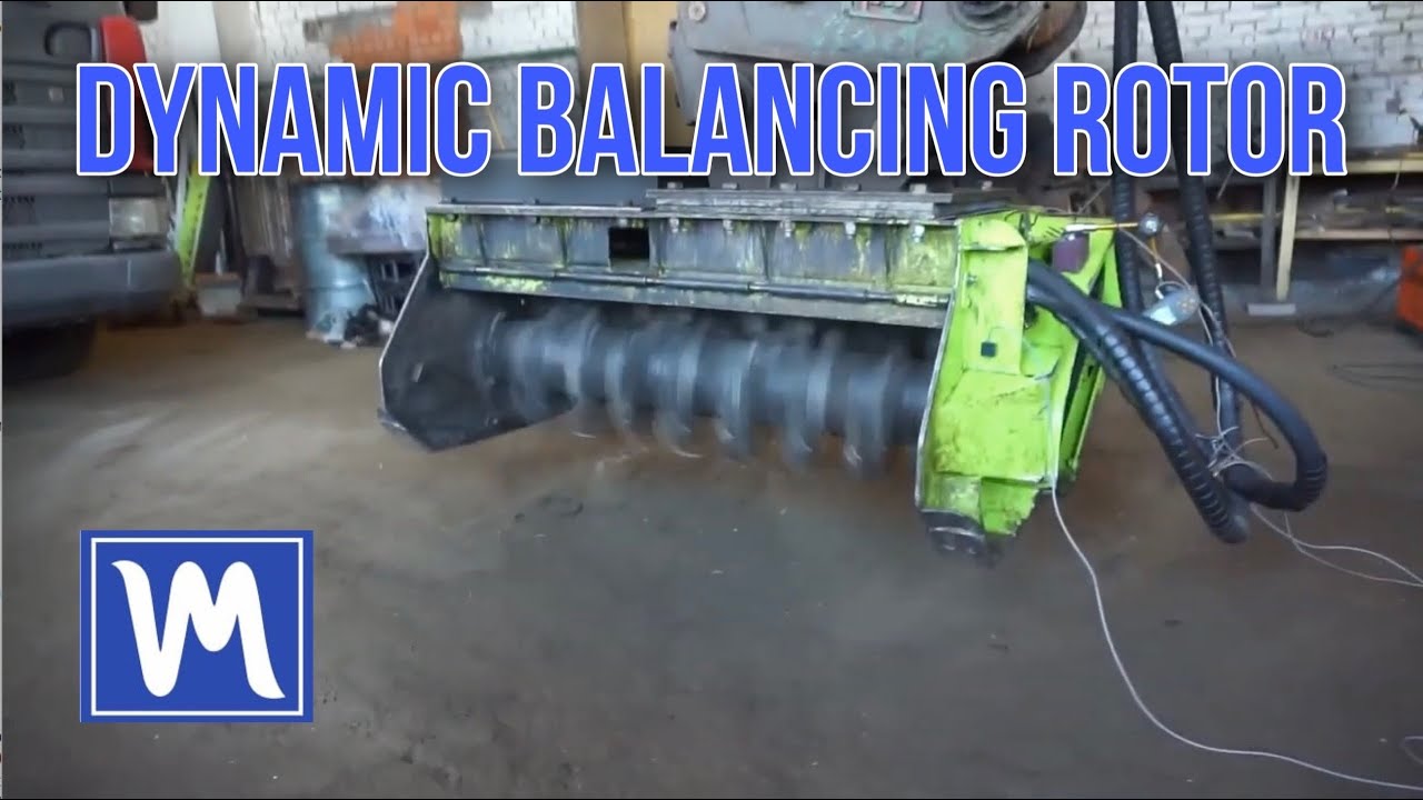
For flail mowers and forestry mulchers, the rotor is a long steel drum carrying anywhere from 20 to 80 swinging flails or fixed teeth. These rotors are large, heavy, and nearly impossible to perfectly manufacture. Every weld bead, every flail bracket, every variation in wall thickness creates a small mass asymmetry. The sum of those asymmetries is the imbalance.
Why It Matters: Forces, Failures, and Money
Imbalance isn't a nuisance — it's a destructive force. The centrifugal force from an unbalanced rotor grows with the square of the RPM. Double the speed, quadruple the force. At operating speed, a moderate imbalance subjects every component in the machine to a hammering cyclic load.
What Breaks First (and How Much It Costs)
- Bearings take the direct hit. An unbalanced rotor can cut bearing life by 30% or more. Quality bearing sets cost €50–€100 each, but the real damage is the 2–4 hours of downtime per replacement. Some operators replace bearings every few days.
- Bearing housings get wallowed out from excessive play. Once the seat is oval, even a new bearing won't run true. Housing repair or replacement: €200–€500.
- Bolts and fasteners work loose continuously. Every bolt on a vibrating machine is trying to unscrew itself. Loose bolts mean lost flails, lost guards, lost production — and a safety risk.
- Frame welds crack. Prolonged vibration fatigue-cracks the mower body. You start seeing reinforcement plates welded over previous reinforcement plates — a Frankenstein machine that's losing structural integrity with every repair.
- Hydraulic fittings leak. Vibration loosens connections and work-hardens seal surfaces. Fluid loss leads to overheating and pump damage.
- The tractor suffers too. Vibration travels through the PTO shaft and three-point hitch into the tractor. Cab mounts, driveline U-joints, and even hydraulic valve bodies on the tractor can deteriorate.
- The operator pays physically. Prolonged whole-body vibration exposure is linked to musculoskeletal injuries. Some operators report feeling vibrations in their hands for hours after finishing work.
ISO Vibration Standards for Agricultural Rotors
Two standards matter here. ISO 21940-11 (formerly ISO 1940-1) defines balance quality grades — how much residual imbalance is acceptable for a given rotor type. ISO 10816-3 (now ISO 20816-3) defines vibration severity zones — how much vibration is acceptable at the bearing housings.
| ISO 21940-11 Grade | Application | Example Equipment |
|---|---|---|
| G40 | Coarse agricultural machinery | Crankshaft-driven machines, rigid rotors with low RPM |
| G16 | Agricultural machinery, general | Flail mowers, forestry mulchers, hammer mills |
| G6.3 | Agricultural machinery, smooth-running | High-RPM shredders, centrifugal pumps, fans |
| G2.5 | Electric motors, precision drives | Process fans, pump impellers, motor armatures |
| Zone | Vibration (mm/s RMS) | Meaning | Action Required |
|---|---|---|---|
| A | < 1.4 | New machine condition | None — excellent |
| B | 1.4 – 2.8 | Acceptable for long-term operation | Monitor periodically |
| C | 2.8 – 4.5 | Only acceptable for short periods | Plan maintenance soon |
| D | > 4.5 | Dangerous — risk of damage | Stop machine. Fix immediately |
A single bearing replacement on a flail mower takes 2–3 hours and costs €50–€100 in parts. If vibration forces you into replacements every 2 weeks instead of every 12 months, that's roughly 24 extra replacements per year — €1,200–€2,400 in parts plus 48–72 hours of lost work time.
One day of downtime during contract season can cost €500–€1,000 in lost revenue. Catastrophic failure (cracked shaft, destroyed rotor) means €1,500–€3,000+ for replacement parts and weeks of waiting.
A Balanset-1A costs €1,975 once. One or two prevented bearing failures pay for it. Every job after that is pure savings.
Equipment Types and Their Balancing Quirks
Not every mower or mulcher behaves the same way. The rotor geometry, flail type, and operating RPM all affect how imbalance develops and how you correct it.
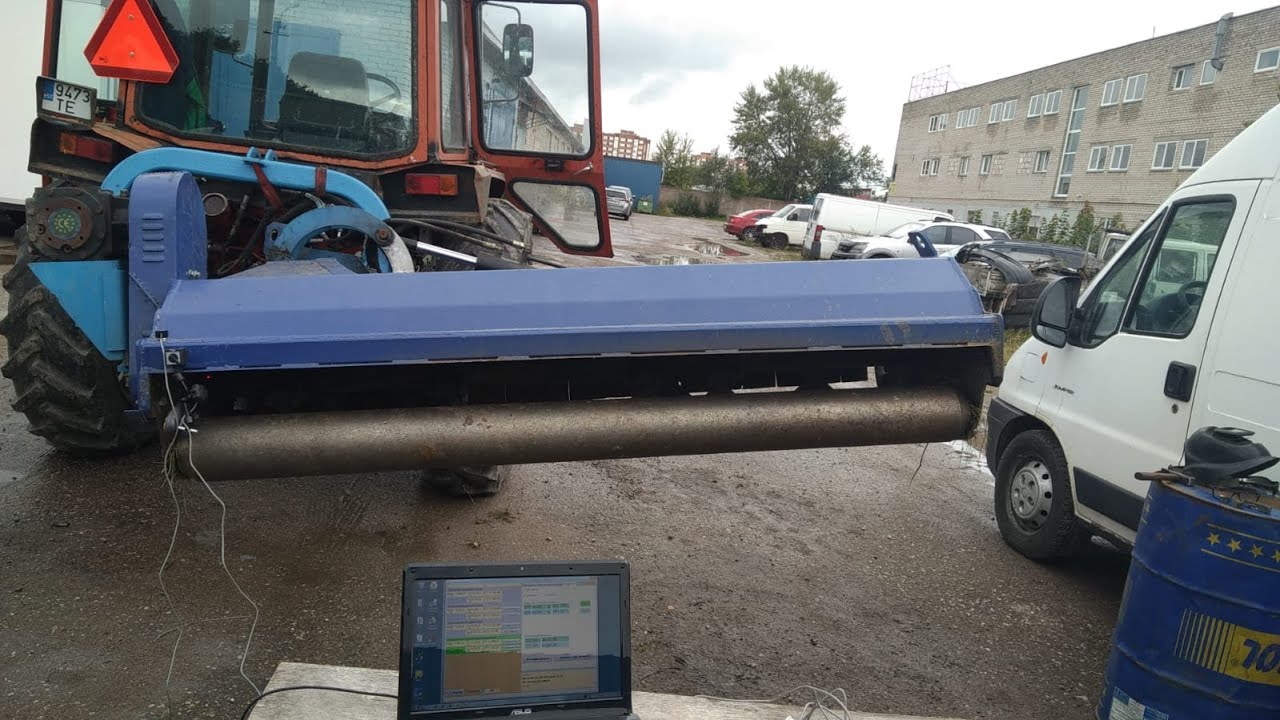
Flail Mower (PTO-driven)
The most common type. Horizontal drum with Y-blades or hammer flails on pivoting brackets. Imbalance usually comes from uneven flail wear, lost flails, or mud buildup. Two-plane balancing needed for drums longer than 1.2 m. Replace worn flails in opposite pairs before balancing.
Forestry Mulcher (Excavator-mounted)
Heavier rotors with fixed carbide teeth. Imbalance develops as teeth wear unevenly or break off during impact with stones and buried metal. These rotors run on hydraulic drives — the RPM can vary, so hold speed steady during measurement. Larger trial weights needed (100–200 g typical).
Verge / Roadside Flail Mower
Higher RPM for fine cutting, making them more sensitive to imbalance. Often has a lighter rotor with many small flails. Even slight imbalance produces noticeable vibration. Target G6.3 grade for smooth operation. Hollow drums can accumulate debris inside — clean before balancing.
Stump Grinder / Land Clearing Drum
The heaviest rotors in this category. Low RPM but massive centrifugal forces due to weight. Imbalance from broken teeth and weld repairs. Often requires two operators — one to run the machine, one to monitor the Balanset. Corrective weights can be 200–500 g per plane.
Static vs Dynamic Imbalance: Why the "Knife-Edge" Method Falls Short
The traditional approach is simple: rest the rotor on two knife-edge supports (or a pair of round bars), let it roll freely, and counterweight the heavy side. When the rotor no longer wants to turn on its own, it's "balanced." This works for static imbalance — where the center of mass is offset from the rotation axis.
For narrow, disc-like rotors (length-to-diameter ratio below about 0.5), static balancing can be adequate — provided the operating speed and the measured bearing response support it. Think of a single-belt pulley or a grinding wheel — the weight distribution error is essentially in one plane.
Flail mower drums are long. A 1.5 m drum on a typical PTO mower has a length-to-diameter ratio of 3:1 or more. Imagine one end of the drum has a heavy spot at the 12 o'clock position, and the other end has a heavy spot at the 6 o'clock position. On knife-edge supports, those two spots counterbalance each other — the rotor sits level and appears "balanced."
Spin that same rotor at 2,000 RPM, and each heavy spot generates centrifugal force pulling outward in its own direction. The result is a couple — a twisting force that rocks the rotor end-to-end. This is dynamic imbalance, and it's invisible when the rotor is stationary.
Rule of thumb: Single-plane (static) balancing is worth considering only for narrow, disc-like rotors with a length-to-diameter ratio below about 0.5, and only when the operating speed and measured response support it. Elongated rotors and rotors with significant couple response require two-plane balancing. For virtually all flail mower drums, forestry mulcher drums, and shredder rotors, this means dynamic balancing is the only effective approach.
Why Shop Balancing Isn't Enough
Some operators send their rotors to a machine shop for bench balancing. The shop mounts the rotor in a balancing machine with its own precision bearings and measures the imbalance. They add weights, verify, and send it back. The rotor returns "perfectly balanced."
You reinstall it. It still vibrates. Why?
- Different bearings. The shop's balancing machine has precision bearings with nearly zero clearance. Your mower's bearings have working clearance, some wear, and may sit in housings that have been wallowed out. The rotor runs at a slightly different center in your machine than it did in theirs.
- Fit tolerances. When you bolt the rotor back in, the shaft-to-bearing fit, keyway alignment, and pulley or coupling position may not be identical to the shop setup. Even 0.01 mm of eccentricity at the coupling introduces imbalance.
- Operating conditions. Under load, the flails swing outward and their mass distribution changes. Thermal expansion of the rotor tube at operating temperature shifts the balance point. PTO shaft alignment and drive belt tension affect the bearing loads.
In-situ balancing (balancing the rotor while it's installed in your machine) accounts for all of these real-world factors. The sensors measure what the bearings actually experience under real operating conditions. That's why in-situ results are typically better than shop results — and the rotor never has to leave the machine.
Preparation: The Pre-Balancing Checklist
Balancing corrects mass distribution. It cannot fix broken parts. Every minute spent on preparation saves ten minutes of troubleshooting later.
- Clean the rotor. Remove all caked mud, wrapped wire, vegetation, and debris — from the outside and inside (hollow drums). Even 50 g of dried mud acts as an unintended counterweight.
- Inspect bearings. Grab the rotor shaft near each bearing and check for play — any radial or axial looseness means the bearing needs replacing first. Listen for grinding or clicking during slow rotation.
- Check every flail and hammer. All must be present, swing freely, and be roughly the same weight. If one is broken or heavily worn, replace it and its diametrically opposite partner. Missing flails are the #1 cause of imbalance in flail mowers.
- Inspect for cracks. Look at the rotor tube, end plates, flail brackets, and frame welds. A cracked rotor will produce erratic vibration that cannot be balanced out — the crack changes shape under centrifugal load.
- Verify belt tension / PTO alignment. A loose belt slips and gives inconsistent RPM. A misaligned PTO shaft introduces vibration that isn't from imbalance. Fix these first.
- Check for soft foot. Are all mounting bolts tight? Is the mower sitting level? Uneven mounting creates a resonance condition that amplifies vibration.
- Lockout/Tagout the engine before touching the rotor. Remove the key. Engage the PTO brake if equipped.
- Wear eye protection when welding, grinding, or during any test run.
- During test runs (rotor spinning), all personnel must stand clear of the plane of rotation. A loose trial weight at 2,000 RPM is a projectile.
- Use hearing protection — exposed flail mower drums at operating RPM easily exceed 95 dB.
- Never reach into the rotor area while the PTO is engaged. Use a rope or stick to apply reflective tape if needed with the rotor stationary.
7-Step Field Balancing Procedure with Balanset-1A
This is the influence coefficient method, which the Balanset-1A automates. You'll make three measurement runs, then install permanent corrective weights. The software handles all the trigonometry.
Pre-Inspection and Preparation
Complete the checklist above. Mark Plane 1 (near bearing 1, typically the drive end) and Plane 2 (near bearing 2, the free end). These are where you'll attach trial weights and permanent corrections.
Weigh your trial weight on a precision scale. A good starting point is 1–3% of the rotor section mass. For a 30 kg drum, that's 300–900 g. For a 5 kg rotor section, 50–150 g. The goal is to cause a measurable 20–30% change in vibration amplitude.
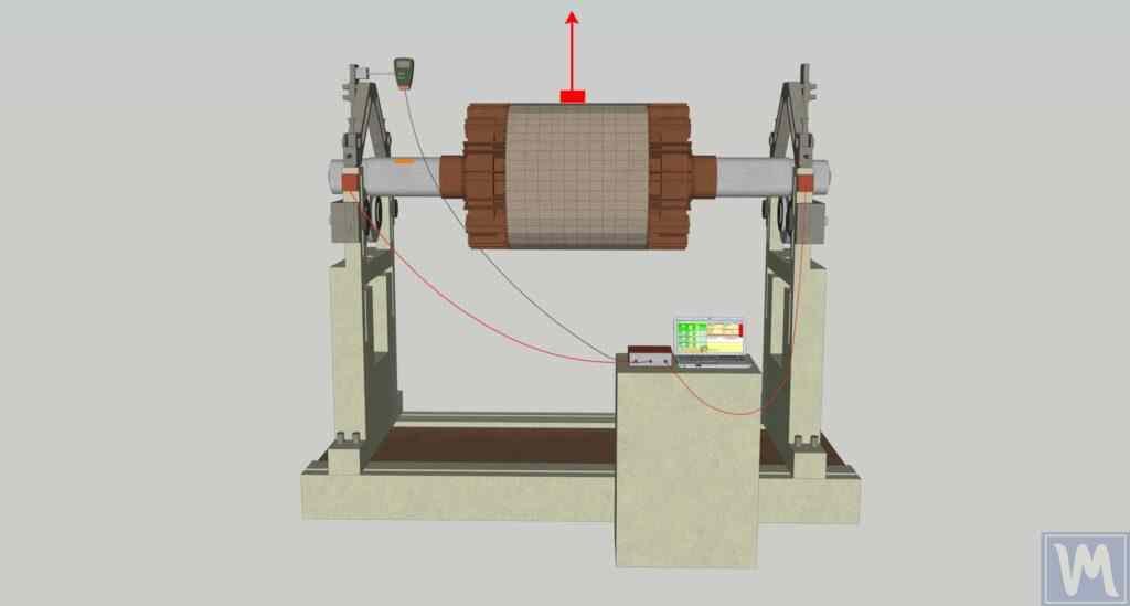
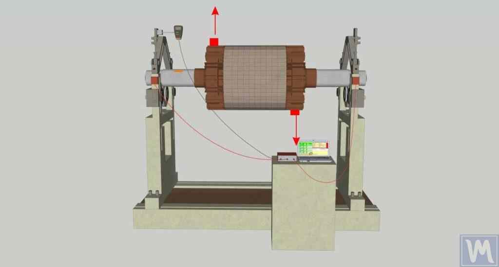
Mount Sensors and Tachometer
Attach vibration sensor 1 to the bearing housing at Plane 1, sensor 2 at Plane 2. Use the magnetic bases and orient sensors perpendicular to the rotor axis (horizontal direction usually gives the strongest signal). Clean the mounting surface — oil and paint reduce the magnetic hold.
Stick reflective tape on the rotor or pulley. Mount the laser tachometer on its magnetic stand, aimed so the laser hits the tape throughout rotation. Connect sensors to Balanset-1A inputs (X1, X2, X3 for tachometer). Connect to laptop via USB.
Run 0 — Record Initial Vibration
Launch Balanset software. Select Two-Plane Balancing mode. Create a new record. Start the rotor at operating RPM (typically 2,000 RPM via PTO). Wait 5–10 seconds for speed to stabilize. Record baseline vibration amplitude (mm/s) and phase angle at both sensors.
Note these values — they're your "before" numbers. Anything above 2.8 mm/s indicates serious imbalance. Above 4.5 mm/s is in the danger zone (Zone D) per ISO 10816-3.
Run 1 — Trial Weight in Plane 1
Stop the rotor. Enter the trial weight mass (grams) and radius (mm) in the software. Bolt the trial weight securely to a flail bracket or weld it temporarily to the drum at Plane 1. Mark the angular position (measure from the reflective tape mark, in the direction of rotation).
Start the rotor. Record vibration with the trial weight installed. Stop the rotor. Remove the trial weight.
Check: did vibration amplitude or phase change by at least 20%? If not, use a heavier trial weight and repeat this run.
Run 2 — Trial Weight in Plane 2
Install the same trial weight at Plane 2 (near the other bearing). Mark the angular position. Run the rotor, record readings. Stop. Remove the trial weight.
After this run, the software has all the data it needs — three vibration measurements (Run 0, Run 1, Run 2) with known trial weight positions. It calculates the influence coefficients and determines the exact corrective masses.
Install Permanent Corrective Weights
The software displays two results: corrective weight mass and angle for Plane 1, and corrective weight mass and angle for Plane 2. Cut steel pieces to the calculated masses (use a scale — precision matters). Measure the angles from your reference mark in the direction of rotation.
Weld the corrective weights at the calculated positions. Use good penetration welds — these weights must survive years of PTO vibration and impacts.
Verify and Document
Run the rotor one final time. The software compares the new vibration to the original. Target: under 1.4 mm/s for excellent (Zone A), under 2.8 mm/s for good (Zone B). If residual vibration is too high, the software offers a trim balance — one additional run to fine-tune the corrections.
Save the report in the Balanset software. Write the balance date and residual vibration on a label attached to the machine. This becomes your maintenance baseline.
Done. The entire procedure typically takes 45–90 minutes once you've done it a few times. The machine should now run noticeably smoother — operators often say it feels like a different machine.
Field Report: Forestry Mulcher, Central Portugal
Machine: Hydraulic forestry mulcher mounted on a 20-ton excavator. Rotor diameter 500 mm, length 1,200 mm, approximately 380 kg. 48 fixed carbide teeth. Operating at 1,800 RPM via hydraulic motor.
Problem: The operator had been replacing main bearings every 10–14 days for three months. The mulcher frame had visible cracks at the mounting points — previously welded twice. The excavator operator reported excessive vibration in the cab. The contractor was losing an average of €400/week in bearing costs and downtime.
What we found: Two teeth were missing from one end of the drum (impact with buried concrete). One tooth was cracked and partially detached. After replacing all three teeth and cleaning dried mud from inside the hollow drum, initial vibration measured 12.8 mm/s at the drive-end bearing and 9.4 mm/s at the free end — deep in ISO Zone D (dangerous).
Balancing procedure: Two-plane dynamic balancing with Balanset-1A. Trial weight: 120 g bolt. Corrective weights: 85 g at 142° on Plane 1, 110 g at 267° on Plane 2. Welded to the drum end plates.
Result: Residual vibration dropped to 1.2 mm/s at the drive end and 1.6 mm/s at the free end — solidly in Zone A. Total job time including tooth replacement: 2.5 hours. Balancing procedure alone: 55 minutes.


Troubleshooting: Still Vibrating After Balancing?
You followed the procedure, installed the corrective weights, and the vibration barely changed. Before questioning the equipment, work through these three categories systematically.
1. Mechanical Problems (Most Common)
- Worn or damaged bearings — even brand-new cheap bearings can have excess internal clearance. Check for play after installation.
- Bent shaft — a bent shaft creates 1× RPM vibration that looks like imbalance but can't be corrected by adding weights. Check shaft runout with a dial indicator: more than 0.05 mm TIR (total indicated runout) is a problem.
- Missing or uneven flails — a single missing 500 g hammer at 200 mm radius creates 500 g × 200 mm = 100,000 g·mm (100 g·m) of imbalance — potentially more than the entire rotor had before balancing.
- Debris inside the drum — dirt, gravel, or vegetation trapped inside a hollow rotor shifts with rotation, making vibration readings erratic and non-repeatable.
- Cracked frame or mounting — cracks change the machine's stiffness and can create resonance. Press on the frame at different points and listen for changes in vibration tone.
- Loose bolts anywhere — check every fastener on the mower, the three-point hitch, and the PTO connection.
2. Conditions During Balancing
- Resonance — if the operating RPM coincides with a natural frequency of the machine (structural resonance), even a perfectly balanced rotor produces high vibration. Try balancing at a slightly different RPM (±10%) if possible.
- Inconsistent RPM — the tractor engine speed must remain stable across all three runs. If the PTO speed varies by more than 5%, the phase data is unreliable.
- Something changed between runs — a sensor shifted, the tractor moved, a flail fell off, the belt slipped. If any measurement condition changed, start over from Run 0.
3. Balancing Procedure Errors
- Trial weight too light — if the vibration change between Run 0 and Run 1 is less than 20%, the software's calculation precision drops. Use a heavier trial weight.
- Forgot to remove the trial weight — before installing permanent corrections, verify the trial weight has been removed. This is the most common error.
- Angle measured wrong — angles must be measured from the reflective tape mark in the direction of rotation. Counter-rotation measurement puts the weight 180° off.
- Tachometer misalignment — if the laser shifted between runs, phase readings are off. Secure it rigidly.
- Sunlight interference — optical tachometers can miss triggers in direct sunlight. Shade the sensor.
- Corrective weight placed at wrong radius — the software calculates for a specific radius. If you weld the weight at a different radius, the effective correction changes proportionally.


Frequently Asked Questions
Can I balance the rotor without removing it from the mower?
Yes — and it's the preferred method. In-situ (on-site) balancing means the rotor stays in the machine. You attach sensors to the bearing housings, run the rotor via PTO, and the Balanset-1A calculates corrections. The result is often better than shop balancing because it accounts for real bearing clearances, housing alignment, and operating loads. Most field jobs take 45–90 minutes.
Which ISO 21940-11 (formerly ISO 1940) balance grade does my mower need?
Most flail mowers and forestry mulchers fall under Grade G16 (general agricultural machinery). Higher-RPM verge mowers and precision shredders may benefit from G6.3. The Balanset-1A software calculates the exact permissible residual imbalance in grams based on your rotor mass and RPM — you don't need to look up tables manually.
How often should I re-balance the rotor?
It depends on your working environment. In forestry and land clearing (stones, buried debris, high-impact work), check balance every 100–200 operating hours or whenever you replace teeth. In lighter-duty pasture mowing, once per season is usually sufficient. Always re-balance after replacing flails, bearings, or making any mechanical changes to the rotor.
Why does my mower still vibrate after the shop balanced the rotor?
The shop balanced the rotor in their machine with their precision bearings — not yours. When you reinstall the rotor, differences in bearing fit, housing wear, keyway alignment, and PTO runout re-introduce imbalance that didn't exist on the bench. In-situ balancing after reinstallation typically reduces vibration further because it corrects for everything in the actual operating environment.
Is it safe to use trial weights at operating RPM?
Yes, when properly secured. The trial weight must be bolted or welded — never taped or wire-tied. Size it at 1–3% of the rotor section mass. The Balanset-1A shows live vibration during each run, so you can monitor whether the trial weight is making things better or worse and stop immediately if needed. All personnel must stand clear of the plane of rotation during runs.
Do I need special training to use the Balanset-1A?
No formal certification is needed. The software walks you through each step — mount sensors, run rotor, attach trial weight, run again, install corrections. Most operators feel confident after 2–3 practice jobs. Vibromera provides video tutorials, a detailed manual, and direct technical support via WhatsApp. The device handles all the math — you follow the prompts and weld where it tells you to.
Your Mower Doesn't Have to Shake
An unbalanced rotor is a constant source of damage — to bearings, welds, bolts, the tractor, and the operator. But it's a solvable problem. With the right preparation and a portable balancer like the Balanset-1A, you can take a machine from 12.8 mm/s vibration down to 1.2 mm/s in under an hour, right in the field, without removing the rotor.
The investment pays for itself after one or two prevented bearing failures. The real return is the months of trouble-free operation that follow — no more daily bearing swaps, no more cracked frames, no more rattling cab panels.
Balance the rotor. Fix the problem at the source. Everything else follows.
0 Comments