ಸಮತೋಲನ ಸೇವೆಗಳು › ಚಾಲನಾ ಶಾಫ್ಟಗಳು, ಪ್ರಕಿರ್ಯೀಯ ಶಾಫ್ಟಗಳು & ಕಾರ್ಡಾನ್ ಶಾಫ್ಟಗಳು
ಚಾಲನಾ ಶಾಫ್ಟ & ಕಾರ್ಡಾನ್ ಶಾಫ್ಟ ಸಮತೋಲನ — ಪರಿಚಯ ಸ್ಥಳಕ್ಕೆ, ಕಾರ್ಯಾಚರಣೆ ವೇಗದಲ್ಲಿ
ಪ್ರೋಪ್ಶಾಫ್ಟ, ಕಾರ್ಡಾನ್ ಶಾಫ್ಟ ಮತ್ತು ಸಂಚರಣೆ ಶಾಫ್ಟಗಳು ಸಂಪೂರ್ಣ ಚಾಲನಾ ವ್ಯವಸ್ಥೆಯಾದ್ಯಂತ ಟಾರ್ಕ್ ಪ್ರಸಾರಿತ ಮಾಡುತ್ತವೆ. ಅಸಮತೋಲಿತ ಶಾಫ್ಟ ಪ್ರತಿಯೊಂದು ಸಂಪರ್ಕಿತ ಘಟಕದ ಮೂಲಕ ಏಕಕಾಲದಲ್ಲಿ ವಿನಾಶಕಾರಿ ಕಂಪನವನ್ನು ಕಳುಹಿಸುತ್ತದೆ. ನಾವು ಚಾಲನಾ ಶಾಫ್ಟಗಳನ್ನು ಸಮತೋಲಿಸುತ್ತೇವೆ ಪರಿಚಯ ಸ್ಥಳಕ್ಕೆ ಕಾರ್ಯಾಚರಣೆ ವೇಗದಲ್ಲಿ — ವಾಹನ ಮತ್ತು ಉದ್ಯೋಗಿಕ ಯಂತ್ರಗಳಿಗೆ ಒಾಕೆ — ಕ್ಯಾಬ್ ಕಂಪನ, ಗಿಯರ್ಬಾಕ್ಸ್ ಧರಣೀಯತೆ ಮತ್ತು ಆರಂಭಿಕ ಯೂನಿವರ್ಸಲ್-ಜಾಯಿಂಟ್ ವಿಫಲತೆ ನಿರ್ಮೂಲನ ಮಾಡುವುದು ತೆಗೆದುಕೊಳ್ಳದೆ.
ಸಂಕ್ಷಿಪ್ತವಾಗಿ: ಚಾಲನಾ ಶಾಫ್ಟ (ಕಾರ್ಡಾನ್/ಪ್ರೋಪ್ಶಾಫ್ಟ) ಸಮತೋಲನ ಎಂಬುದು ಒಂದು ಎರಡು-ತಿದ್ದುವ ಸಮತಲ ಪರಿಚಯ ಕ್ರಮವಿಧಿಯಾಗಿದ್ದು, ಶಾಫ್ಟ ತನ್ನ ಸ್ವಂತ ಯೋಕ್ ಮತ್ತು ಸಹಾಯಕ ತಾಮ್ರಪತ್ರಗಳಲ್ಲಿ ಕಾರ್ಯಾಚರಣೆ ವೇಗದಲ್ಲಿ ತಿರುಗುತ್ತಿರುವಾಗ ಮಾಡಲಾಗುತ್ತದೆ. Balanset-1A ಪ್ರತಿಯೊಂದು ತಿದ್ದುವ ಸಮತಲದಲ್ಲಿ ಕಂಪನ ವೈಪ್ಲಿಟ್ಯೂಡ್ ಮತ್ತು ಫೇಜ್ ಅನ್ನು ಅಳೆಯುತ್ತದೆ, ಪ್ರಭಾವ-ಗುಣಾಂಕ ವಿಧಿಯಿಂದ ನಿಖರ ತಿದ್ದುವ ದ್ರವ್ಯಮಾನ ಮತ್ತು ಕೋನವನ್ನು ಲೆಕ್ಕಹಾಕುತ್ತದೆ ಮತ್ತು ತೂಕವನ್ನು ಸರಿಸಲು ನಿಮ್ಮನ್ನು ಮಾರ್ಗದರ್ಶನ ಮಾಡುತ್ತದೆ — ಕೆಲಸಾಗಾರ ಇಲ್ಲ, ತೆಗೆದುಕೊಳ್ಳುವುದು ಇಲ್ಲ. ಉಳಿದಿರುವ ಅಸಮತೋಲನವನ್ನು ISO 21940-11 (G6.3 ಅಥವಾ G2.5) ನಿಶ್ಚೆಯಾಗಿ ಪರಿಶೀಲಿಸಲಾಗುತ್ತದೆ ಮತ್ತು ವರದಿಯಲ್ಲಿ ದಾಖಲೆ ಮಾಡಲಾಗುತ್ತದೆ.
ನಿಮ್ಮ ಡ್ರೈವ್ಶಾಫ್ಟ್ ಅಸಮತೋಲಿತವಾಗಿದೆ ಎಂಬ ಸಂಕೇತಗಳು
ಡ್ರೈವ್ಶಾಫ್ಟ್ ಅಸಮತೋಲನವು ವಾಹನ ಅಥವಾ ಯಂತ್ರದ ವೇಗದೊಂದಿಗೆ ಬೆಳೆಯುವ ವಿಶಿಷ್ಟವಾದ ಕಂಪನವನ್ನು ಉಂಟುಮಾಡುತ್ತದೆ. ಸ್ಪಷ್ಟವಾದ ಸೂಚಕಗಳು ಇಲ್ಲಿವೆ:
ಡ್ರೈವ್ಶಾಫ್ಟ್ಗಳು ತಮ್ಮ ಸಮತೋಲನವನ್ನು ಸೋಲುವುದು ಏಕೆ — ಮತ್ತು ಅದರ ವೆಚ್ಚ ಏನು
ಡ್ರೈವ್ಶಾಫ್ಟ್ಗಳು ದೀರ್ಘ, ತೆಳುವಾದ ಪರಿಭ್ರಮಣ ರಚನೆಗಳಾಗಿದ್ದು, ಅವುಗಳು ಸ್ವಾಭಾವಿಕವಾಗಿ ಎರಡು-ಸಮತೋಲನ ಸಮತೋಲನಕ್ಕೆ ಪ್ರವೃತ್ತವಾಗಿರುತ್ತವೆ. ತಾಜೇ ಹಾನಿ ಸೇವೆಯಲ್ಲಿ ಸಂಗ್ರಹವಾಗುತ್ತದೆ: ಆಘಾತದ ಕುಳಿ ಗುರುತುಗಳು ರಸ್ತೆ ಎಳೆಯಿಂದ ಟ್ಯೂಬ್ ಗೋಡೆಯನ್ನು ವಿರೂಪಗೊಳಿಸುತ್ತದೆ; ರಿಪೇರ್ ವೆಲ್ಡ್ಗಳು ಅಸಮ ದ್ರವ್ಯರಾಶಿ ಸೇರಿಸುತ್ತದೆ; ಕೋರೋಶನ್ ಮೇಲ್ಮೈಯನ್ನು ಅಸಮಾನವಾಗಿ ಕರಕಸುತ್ತದೆ; ಯೋಕ್ ಅಥವಾ ಫ್ಲ್ಯಾಂಜ್ ಪ್ರತಿಸ್ಥಾಪನಗಳು ದ್ರವ್ಯರಾಶಿ ಕೇಂದ್ರವನ್ನು ಸ್ಥಳಾಂತರಿತ ಮಾಡುತ್ತವೆ. ಯಂತ್ರಾಗಾರದಲ್ಲಿ ಸಮತೋಲಿತ ಶಾಫ್ಟ್ ಕೂಡ ಒಂದೇ ಪಾತಾಳ ಹೊಡೆತ ಅಥವಾ ಒಂದು ಬೆಸೆಗೆಯ ನಂತರ ಹಲವಾರು ಗ್ರಾಮ್ ಆಫ್ಸೆಟ್ ಅನ್ನು ಅಭಿವೃದ್ಧಿ ಮಾಡಬಹುದು.
ಪರಿಣಾಮಗಳು ವ್ಯವಸ್ಥಾಪಕವಾಗಿವೆ. ಶಾಫ್ಟ್ ಗಿಯರ್ಬಾಕ್ಸ್ ಅನ್ನು ಆಕ್ಸಲ್ನಿಗೆ (ಅಥವಾ ಮೋಟರ್ ಅನ್ನು ಲೋಡ್ಗೆ) ಸಂಪರ್ಕಿಸುವುದರಿಂದ, ಅದರ ಕಂಪನವು ಸರಪಳಿಯಲ್ಲಿನ ಪ್ರತಿಯೊಂದು ಲಿಂಕ್ ಅನ್ನು ಏಕಕಾಲದಲ್ಲಿ ಲೋಡ್ ಮಾಡುತ್ತದೆ. ಸರ್ವজನೀನ ಜಾಯಿಂಟ್ಗಳು, ಬೇರಿಂಗ್ಗಳು ಮತ್ತು ರಬ್ಬರ್ ಮೌಂಟ್ಗಳನ್ನು ಬದಲಾಯಿಸುವುದು ಮೂಲ ಕಾರಣ — ಪರಿಭ್ರಮಣ ಅಸಮತೋಲನ — ಪ್ರತಿ ನಿರ್ಮಾಣ ಸ್ಫಟ ವಿಫಲತೆಗಳ ಅನುಕ್ರಮವನ್ನು ನಿರ್ಮಾಣ ಹಿಸ್ಸೆ ಕಾಯಿಲ್ನೊಂದಿಗೆ ನೀಗುತ್ತದೆ. ಒಂದೇ ಕ್ಷೇತ್ರ-ಸಮತೋಲನ ಕೆಲಸವು ಮೂಲವನ್ನು ಸರಿಪಡಿಸುತ್ತದೆ ಮತ್ತು ಇದನ್ನು ಅನುಸರಿಸುವ ಸಮಯಕ್ಕೆ ಮುಂಚೆ ವೈಫಲ್ಯಗಳ ಅನುಕ್ರಮವನ್ನು ನಿರ್ಮೂಲನ ಮಾಡುತ್ತದೆ.
ಕಂಪನವನ್ನು ಅರ್ಧೇಕ ಮಾಡುವುದು ಬೀರಿಂಗ್ ಆಯುಶ್ಯನನ್ನು ಗುಣಿಸುವುದು ಏಕೆ
ನಾವು ಡ್ರೈವ್ ಶಾಫ್ಟ್ ಸಮತೋಲನ ಮಾಡುವ ರೀತಿ — ಹಂತ ಹಂತವಾಗಿ
Balanset-1A ಳ ಕಾರ್ಡಾನ್ ಶಾಫ್ಟ್ ಅಥವಾ ಪ್ರಾಪ್ಶಾಫ್ಟ್ನ ಕ್ಷೇತ್ರ ಸಮತೋಲನ ಪ್ರಭಾವ-ಗುಣಾಂಕ ವಿಧಾನವನ್ನು ಬಳಸುತ್ತದೆ ಮತ್ತು ವಾಹನ ಅಥವಾ ಯಂತ್ರದಿಂದ ತೆಗೆದುಕೊಳ್ಳುವ ಅಗತ್ಯವಿಲ್ಲ:
- ಮೂಲ ಅಳತೆಯನ್ನು ಪಡೆಯಿರಿ. ಕಂಪನ ಸಂವೇದಕಗಳನ್ನು ಪ್ರತಿ ಸಮತೋಲನ ಸುತೀರ್ಣಕ್ಷೇತ್ರದ ಹತ್ತಿರ ಬೀರಿಂಗ್ ಹೌಸಿಂಗ್ಗೆ (ಅಥವಾ ಮಾನುಷಕ-ಮಧ್ಯೆ ಶಾಫ್ಟ್ಗೆ ಸಂಬಂಧಿತ ಚ್ಯಾಸಿಸ್ ಸದಸ್ಯಕ್ಕೆ) ಜೋಳಿಸಲಾಗುತ್ತದೆ. ಲೇಸರ್ ಟಾಕೋ ತಿರುಗುವ ಶಾಫ್ಟ್ನಲ್ಲಿ ಹಂತ ಚಿಹ್ನೆಯನ್ನು ಓದುತ್ತದೆ. ವಿಶಿಷ್ಟ ಕಾರ್ಯಾಚರಣ ವೇಗದಲ್ಲಿ ಒಂದು ರನ್ ಎರಡೂ ಅಳತೆ ಬಿಂದುಗಳಲ್ಲಿ ವೈಶಾಲ್ಯ ಮತ್ತು ಹಂತವನ್ನು ರೆಕಾರ್ಡ್ ಮಾಡುತ್ತದೆ.
- ಪರೀಕ್ಷೆಯ ತೂಕವನ್ನು ಸೇರಿಸಿ. ಒಂದು ಪರೀಕ್ಷೆ ದ್ರವ್ಯರಾಶಿಯನ್ನು ಒಂದು ಸಮತೋಲನ ಸುತೀರ್ಣಕ್ಷೇತ್ರದ ಹತ್ತಿರ ತಿಳಿದ ಕೋನೀಯ ಸ್ಥಾನದಲ್ಲಿ ಶಾಫ್ಟ್ ಟ್ಯೂಬ್ಗೆ ಜೋಳಿಸಲಾಗುತ್ತದೆ. ಅದೇ ವೇಗದಲ್ಲಿ ಎರಡನೇ ರನ್ ತಿಳಿದಿರುವ ದ್ರವ್ಯರಾಶಿಗೆ ಶಾಫ್ಟ್ನ ಪ್ರತಿಕ್ರಿಯೆಯನ್ನು ಸೆರೆಹಿಡಿಯುತ್ತದೆ, ಆ ಸುತೀರ್ಣಕ್ಷೇತ್ರದ ಪ್ರಭಾವ ಗುಣಾಂಕವನ್ನು ಸ್ಥಾಪಿಸುತ್ತದೆ.
- ಸಾಧನವನ್ನು ಗಣನೆ ಮಾಡುವ ಅವಕಾಶ ನೀಡಿ. Balanset-1A ಎರಡು-ಸುತೀರ್ಣಕ್ಷೇತ್ರ ಪ್ರಭಾವ-ಗುಣಾಂಕ ಅಲ್ಗಾರಿದಮ್ ಅನ್ನು ಅನ್ವಯಿಸುತ್ತದೆ ಮತ್ತು ಶಾಫ್ಟ್ನ ಪ್ರತಿಯೊಂದು ತುದಿಗೆ ನಿಖರವಾದ ಸಮತೋಲನ ದ್ರವ್ಯರಾಶಿ ಮತ್ತು ಕೋನವನ್ನು ಏಕಕಾಲದಲ್ಲಿ ನೀಡುತ್ತದೆ — ಯಾವುದೇ ಹಸ್ತ ಗಣಿತ ಅಗತ್ಯವಿಲ್ಲ.
- ಸಮತೋಲನ ಓಜೆಸುಗಳನ್ನು ಸಿದ್ಧಪಡಿಸಿ. ನಳಿ ಕ್ಲ್ಯಾಂಪ್ಗಳು, ಲೆಕ್ಕೆ ಹೊಳೆದ ಮೊಬರಿಗಳು ಅಥವಾ ಸಮತೋಲನ ಪ್ಯಾಡ್ಗಳನ್ನು ಪ್ರತಿಯೊಂದು ಯೋಕ್ ಅಥವಾ ಪರಿಭ್ರಮಣೆಯ ಹತ್ತಿರ ಸೂಚಿತ ಕೋನೀಯ ಸ್ಥಾನಗಳಲ್ಲಿ ಅನ್ವಯ ಮಾಡಲಾಗುತ್ತದೆ. ಪರೀಕ್ಷೆ ಓಜೆಸುಗಳನ್ನು ತೆಗೆದುಕೊಳ್ಳಲಾಗುತ್ತದೆ ಅವು ಪರಿಹಾರದಲ್ಲಿ ಸೇರಿಸಲಾಗಿಲ್ಲದಿದ್ದರೆ.
- ಪರಿಶೀಲಿಸಿ. ಕಾರ್ಯಾಚರಣ ವೇಗದಲ್ಲಿ ಅಂತಿಮ ಅಳತೆ ರನ್ ಉಳಿದ ಅಸಮತೋಲನ ISO 21940-11 ಸಹನೀಯತೆಯ ಒಳಗೆ ಮತ್ತು ವೇಗ-ಅವಲಂಬಿತ ಕಂಪನವನ್ನು ನಿರ್ಮೂಲಿತ ಮಾಡಲಾಯಿತೆ ಎಂದು ದೃಢೀಕರಿಸುತ್ತದೆ. ಫಲಿತಾಂಶ ದಾಖಲೆ ಮಾಡಲಾಗುತ್ತದೆ.
ನಾವು ಸಮತೋಲಿತ ಮಾಡುವುದು
- ಪ್ರಾಪ್ಶಾಫ್ಟ್ಗಳು ಮತ್ತು ಕಾರ್ಡಾನ್ ಶಾಫ್ಟ್ಗಳು (ಟ್ರಕ್ಗಳು, ಬಸ್ಗಳು, ಆಫ-ರೋಡ್ ವಾಹನಗಳು)
- ಮೋಟಾರ್-ಗ್ರೇಡರ್ ಮತ್ತು ನಿರ್ಮಾಣ-ಯಂತ್ರ ಡ್ರೈವ್ಲೈನ್ಗಳು
- ಕೃಷಿ ಯಂತ್ರ ಶಾಫ್ಟ್ಗಳು (ಸಂಯೋಜಕ, ಸುಗ್ರಹಕ, ಹೆಡರ್ ಡ್ರೈವ್ಗಳು)
- ಕೈಗಾರಿಕ ಕಾರ್ಡಾನ್-ಶಾಫ್ಟ್ ಸಂಯೋಜನಗಳು
- ವಿ-ಬೆಲ್ಟ್ ಮತ್ತು ಫ್ಲ್ಯಾಟ್-ಬೆಲ್ಟ್ ಪುಲ್ಲಿ ಅಸೆಂಬ್ಲಿಗಳು
- ಟೈಮಿಂಗ್-ಬೆಲ್ಟ್ ಪುಲ್ಲಿ ಮತ್ತು ಸ್ಪ್ರೋಕೆಟ್ ಶಾಫ್ಟ್ಗಳು
- ಫ್ಲೈವೀಲ್ಗಳು ಮತ್ತು ಫ್ಲೈವೀಲ್-ರಿಂಗ್ ಅಸೆಂಬ್ಲಿಗಳು
- ರಬ್ಬರೈಸ್ಡ್ ಮತ್ತು ಲ್ಯಾಗ್ಡ್ ಟ್ರಾನ್ಸ್ಮಿಶನ್ ಶಾಫ್ಟ್ಗಳು
- ಜ್ಯಾಕ್ಶಾಫ್ಟ್ಗಳು ಮತ್ತು ಇಂಟರ್ಮಿಡಿಯೇಟ್-ಡ್ರೈವ್ ಅಸೆಂಬ್ಲಿಗಳು
ಸಹನಶೀಲತೆ ಮತ್ತು ಮಾನದಂಡಗಳು
Balanset-1A — ನಿಮ್ಮ ಸಂಪೂರ್ಣ ಸೈಟ-ನಲ್ಲಿ ಸಮತೋಲನ ಕಿಟ್
ಈ ಪುಟದಲ್ಲಿ ಎಲ್ಲವೂ ಒಂದು ಪೋರ್ಟೇಬಲ್ ಯಂತ್ರದೊಂದಿಗೆ ಮಾಡಲಾಗುತ್ತದೆ: ಬ್ಯಾಲೆನ್ಸೆಟ್-1ಎ. ಇದು ಎರಡು-ಚ್ಯಾನೆಲ್ ಡೈನಾಮಿಕ್ ಸಮತೋಲಕ ಮತ್ತು ವೈಬ್ರೇಶನ್ ವಿಶ್ಲೇಷಕ ಇದು ಕಠಿಣ ರೋಟರ್ಗಳನ್ನು ಸಮತೋಲಿತ ಮಾಡುತ್ತದೆ — ಕಾರ್ಡಾನ್ ಶಾಫ್ಟ್ಗಳು, ಪ್ರಾಪ್ಶಾಫ್ಟ್ಗಳು ಮತ್ತು ಪುಲ್ಲಿ ಅಸೆಂಬ್ಲಿಗಳು — ಅವುಗಳ ಸ್ವಂತ ಬೆಲ್ಲಾಣಿಗಳಲ್ಲಿ, ಕಾರ್ಯಾಚರಣ ವೇಗದಲ್ಲಿ, 3-ಚಲನೆಯ ಪ್ರಭಾವ-ಗುಣಾಂಕ ವಿಧಿಯನ್ನು ಬಳಸಿ. ಸಾಫ್ಟ್ವೇರ್ ಏಕಕಾಲದಲ್ಲಿ ಎರಡೂ ಸಮತಲಗಳಿಗೆ ನಿಖರವಾದ ತಿದ್ದುವ ದ್ರವ್ಯರಾಶಿ ಮತ್ತು ಕೋನವನ್ನು ಲೆಕ್ಕ ಹಾಕುತ್ತದೆ ಮತ್ತು ಸಂಪೂರ್ಣ ವರದಿಯನ್ನು ಉಳಿಸುತ್ತದೆ.
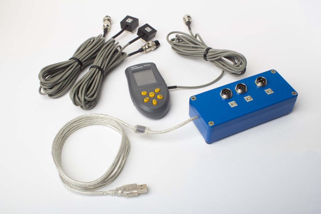
ಪೂರ್ಣ ಸಾಧನ ಪೆಟ್ಟಿಗೆಯಲ್ಲಿ ಏನಿದೆ
€1,975 · ಸಂಪೂರ್ಣ ಕಿಟ್, ಸ್ಟಾಕ್ನಲ್ಲಿ, VAT ಸರಕುಪತ್ರೆ
- ಇಂಟರ್ಫೇಸ್ ಮಾಪನ ಘಟಕ (USB, 2 ಚಾನೆಲ್ಗಳು)
- ಎರಡು ವೈಬ್ರೇಶನ್ ಆಕ್ಸೆಲೆರೋಮೀಟರ್ಗಳು (4 ಮೀ ಕೇಬಲ್, 10 ಮೀ ಐಚ್ಛಿಕ)
- ಲೇಸರ್ ಟ್যಾಕೋಮೀಟರ್ / ಆಪ್ಟಿಕಲ್ ಫೇಸ್ ಸೆನ್ಸರ್ (50–500 mm)
- ಸಂವೇದಕದ ಮ್ಯಾಗ್ನೆಟಿಕ್ ಸ್ಟ್ಯಾಂಡ್
- ಪರೀಕ್ಷಾ ಮತ್ತು ತಿದ್ದುಪಡಿ ತೂಕಗಳಿಗೆ ಡಿಜಿಟಲ್ ಸ್ಕೇಲ್
- ವಿಂಡೋಸ್ ಬ್ಯಾಲೆನ್ಸಿಂಗ್ ಮತ್ತು ವಿಶ್ಲೇಷಣ ಸಾಫ್ಟ್ವೇರ್
- ಪ್ಲಾಸ್ಟಿಕ್ ಟ್ರಾನ್ಸ್ಪೋರ್ಟ್ ಕೇಸ್
ಸಂಪೂರ್ಣ ಕಿಟ್
ಯೂನಿಟ್ · 2 ಸೆನ್ಸರ್ಗಳು · ಲೇಸರ್ ಟ್ಯಾಕೋಮೀಟರ್ · ಮ್ಯಾಗ್ನೆಟಿಕ್ ಸ್ಟ್ಯಾಂಡ್ · ಡಿಜಿಟಲ್ ಸ್ಕೇಲ್ · ಸಾಫ್ಟ್ವೇರ್ · ಟ್ರಾನ್ಸ್ಪೋರ್ಟ್ ಕೇಸ್. ಬಾಕ್ಸ್ನಿಂದಲೇ ಬ್ಯಾಲೆನ್ಸಿಂಗ್ ಆರಂಭಿಸಲು ಅಗತ್ಯವಿರುವ ಎಲ್ಲವೂ.
OEM ಸೆಟ್
ಯೂನಿಟ್ · 2 ಸೆನ್ಸರ್ಗಳು · ಲೇಸರ್ ಟ್ಯಾಕೋಮೀಟರ್ · ಸಾಫ್ಟ್ವೇರ್. ಈಗಾಗಲೇ ಸ್ಟ್ಯಾಂಡ್, ಸ್ಕೇಲ್ ಮತ್ತು ಕೇಸ್ ಹೊಂದಿರುವ ಅಥವಾ ಬ್ಯಾಲೆನ್ಸಿಂಗ್ ಯಂತ್ರದಲ್ಲಿ ಯೂನಿಟ್ ಅನ್ನು ಅಳವಡಿಸುವ ಇಂಟಿಗ್ರೇಟರ್ಗಳಿಗಾಗಿ.
| ಪ್ಯಾರಾಮೀಟರ್ | ಮೌಲ್ಯ |
|---|---|
| ಮಾಪನ ಚ್ಯಾನೆಲ್ಗಳು | 2 (ಏಕ- & ದ್ವಿ-ತಲಾ ಬ್ಯಾಲೆನ್ಸಿಂಗ್) |
| ವೈಬ್ರೇಶನ್ ವೇಗ ಶ್ರೇಣಿ | 0.2–80 mm/s RMS |
| ಆವೃತ್ತಿ ವ್ಯಾಪ್ತಿ | 5–1000 Hz (≤10% amplitude error above 550 Hz) |
| ಮಾಪನ ನಿಖುರತೆ | ±5% ಪೂರ್ಣ ಪ್ರಮಾಣ |
| ವಿಧಾನ | 3-ರನ್ ಪ್ರಭಾವ-ಗುಣಾಂಕ (1 ಅಥವಾ 2 ತಲಾಗಳು) |
| ವಿಶ್ಲೇಷಣೆ | ವೈಶಾಲ್ಯ & 1× ನಲ್ಲಿ ಫೇಜ್, FFT ಸ್ಪೆಕ್ಟ್ರಮ್ & ತರಂಗ ರೂಪ, ಸಾಂಗ್ರಹಿತ ವರದಿಗಳು |
| ಲ್ಯಾಪ್ಟಾಪ್ | ಸೇರಿಲ್ಲ (ವಿಂಡೋಸ್ PC, ವಿನಂತಿಯ ಮೇರೆಗೆ ಲಭ್ಯವಿದೆ) |
ಸ್ಥಳದಲ್ಲಿ ಸಮತೋಲನ ಶಾಸ್ತ್ರೀಯ ಸಮತೋಲನ ಯಂತ್ರ — ಯಾವುದು ಸರಿಯಾದದೆ?
ಎರಡೂ ವಿಧಾನಗಳು ನಿಖರವಾದ ಫಲಿತಾಂಶಗಳನ್ನು ತೆರೆದುಕೊಳ್ಳುತ್ತವೆ, ಆದರೆ ಅವು ವಿವಿಧ ಪರಿಸ್ಥಿತಿಗಳಿಗೆ ಸೂಕ್ತವಾಗಿವೆ. ನಿರ್ಧಾರ ತೆಗೆದುಕೊಳ್ಳಲು ಈ ಟೇಬಲ್ ಬಳಸಿ:
| ಘಟಕ | ಕ್ಷೇತ್ರ ಸಮತೋಲನ (Balanset-1A) | ಸಮತೋಲನ ಯಂತ್ರ (ಕಾರ್ಯಾಲಯ) |
|---|---|---|
| ಶಾಫ್ಟ್ ತೆಗೆದುಹಾಕುವಿಕೆ ಅಗತ್ಯ | ಇಲ್ಲ | ಹೌದು |
| ಸ್ಥಾಪಿತ ಸಾಲಿನ ವಿಷಯವನ್ನು ಪರಿಗಣಿಸುತ್ತದೆ | ಹೌದು | ಇಲ್ಲ |
| ಸ್ಥಳದಲ್ಲಿ, ಯಾವುದೇ ವಾಹನ ನಿರ್ಬಂಧ ಇಲ್ಲ | ಹೌದು | ಇಲ್ಲ |
| ಎರಡು-ಸಮತಲ ಏಕಕಾಲಿಕ ತಿದ್ದುಪಡಿ | ಹೌದು | ಹೌದು |
| ISO 21940-11 ಸಮ್ಮತಿ ವರದಿ | ಹೌದು | ಹೌದು |
| ದೀರ್ಘ/ಭಾರೀ ಡ್ರೈವ್ ಶಾಫ್ಟ್ಗಳಿಗೆ ಸೆಳೆಯುವ | ಹೌದು | ಸಾಧ್ಯ |
| ಬಹಳ ಹೆಚ್ಚಿನ ನಿಖುರತೆಗೆ ಸೆಳೆಯುವ (<G1) | ಸಾಧ್ಯ | ಹೌದು |
| ವಹನೀಯ (ಬಹುಸಂಖ್ಯೆ ಯಂತ್ರಗಳಲ್ಲಿ ಬಳಸು) | ಹೌದು | ಇಲ್ಲ |
ನೈಜ ಡ್ರೈವ್ ಶಾಫ್ಟ್-ಸಮತೋಲನ ಪ್ರಕರಣಗಳು
ಡ್ರೈವ್ ಶಾಫ್ಟ್ ಸಮತೋಲನ
ಇಂಡಸ್ಟ್ರಿಯಲ್ ಡ್ರೈವ್ ಶಾಫ್ಟ್ನ ಎರಡು-ಸಮತಲ ಕ್ಷೇತ್ರ ಸಮತೋಲನ, ವೇಗ-ಅವಲಂಬಿತ ಕಂಪನವನ್ನು ತೆಗೆದುಹಾಕುತ್ತದೆ ಮತ್ತು U-ಜಾಯಿಂಟ್ ಹೊರೆ ಕಡಿಮೆ ಮಾಡುತ್ತದೆ.
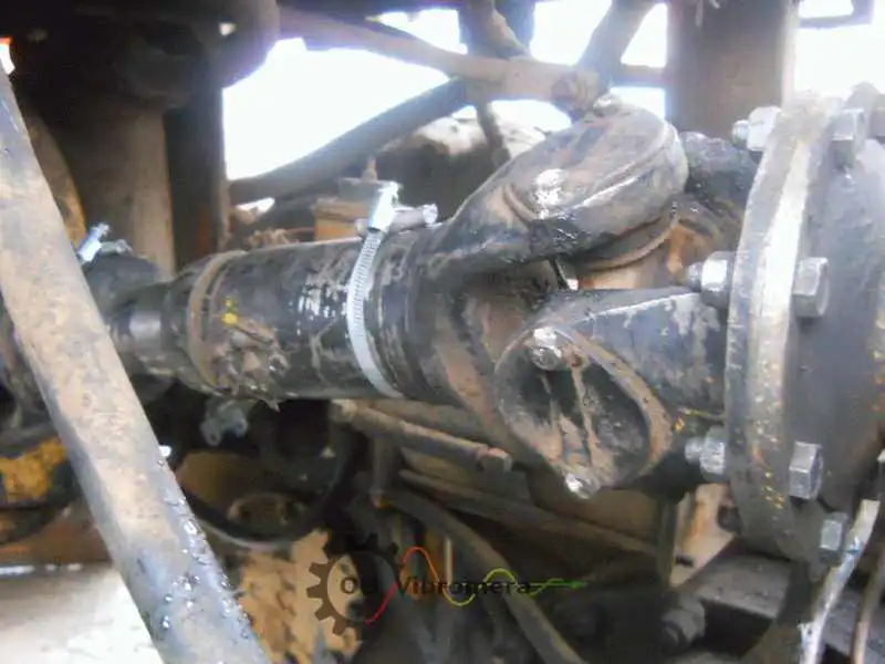
ವಾಹನದಲ್ಲಿ ಡ್ರೈವ್ ಶಾಫ್ಟ್
ಡ್ರೈವ್ಲೈನ್ನಿಂದ ಮೇಲಕ್ಕೆ ಎತ್ತದೆ ಇಲ್ಲದೆ, ರಸ್ತೆಯ ವೇಗದಲ್ಲಿ ವಾಹನದ ಅಡಿಯಲ್ಲಿ ಪ್ರಾಪ್ಶಾಫ್ಟ್ ಸ್ಥಳದಲ್ಲಿ ಸಮತೋಲಿತವಾಗಿದೆ.
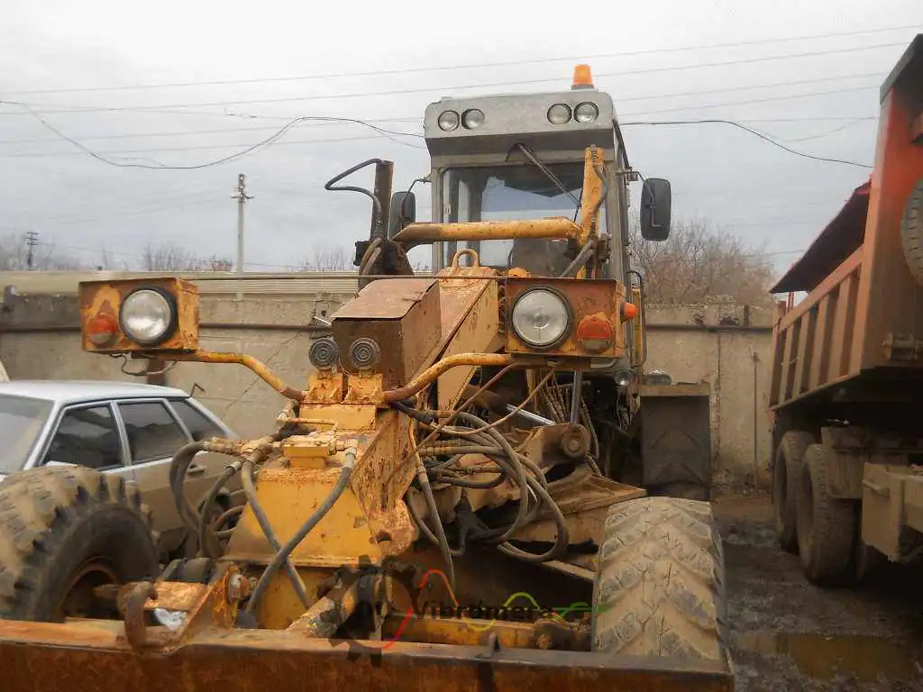
ಮೋಟರ್ ಗ್ರೇಡರ್ನಲ್ಲಿ ಕಾರ್ಡಾನ್
ಕಾರ್ಡಾನ್ ಶಾಫ್ಟ್ ಕೆಲಸ ಮಾಡುತ್ತಿರುವ ಮೋಟರ್ ಗ್ರೇಡರ್ನಲ್ಲಿ ನೇರವಾಗಿ ಸಮತೋಲಿತವಾಗಿದೆ, ಯಂತ್ರ ನಿರ್ಬಂಧ ಇಲ್ಲದೆ ಕ್ಯಾಬ್ ಕಂಪನವನ್ನು ಸರಿಪಡಿಸುತ್ತದೆ.
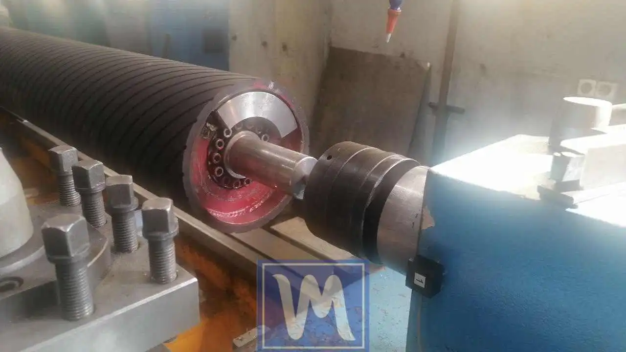
ರಬರ್ ಆವೃತ ಶಾಫ್ಟ್ಗಳು
ಲ್ಯಾಥ್ನಲ್ಲಿ ರಬರ್-ಲೈನ್ ಟ್ರಾನ್ಸ್ಮಿಷನ್ ಶಾಫ್ಟ್ಗಳ ಡೈನಾಮಿಕ್ ಸಮತೋಲನ, G2.5 ಸಹನಶೀಲತೆ ಸಾಧಿಸುತ್ತದೆ.
ಉಚಿತ ಡ್ರೈವ್ಶಾಫ್ಟ್ ಕ್ಯಾಲ್ಕುಲೇಟರ್ಗಳು
ಡ್ರೈವ್ಶಾಫ್ಟ್ ತೋಲನ FAQ
ಪ್ರೊಪ್ಶಾಫ್ಟ್ ಅನ್ನು ವಾಹನದಿಂದ ತೆಗೆಯದೆ ತೋಲನ ಮಾಡಬಹುದೇ?
ಡ್ರೈವ್ಶಾಫ್ಟ್ ಯಾವಾಗಲೂ ಎರಡು-ಸಮತಲ ತೋಲನದ ಅಗತ್ಯವಿದೆ?
ನನ್ನ ಪ್ರೊಪ್ಶಾಫ್ಟ್ ಅನ್ನು ಹೊಸ OEM ಭಾಗದೊಂದಿಗೆ ಬದಲಾಯಿಸಲಾಯಿತು ಆದರೆ ಕಂಪನವು ಇನ್ನೂ ಅಕ್ಕಿತ್ತೆ. ಇದು ಏಕೆ?
ಅದೇ ಸಾಧನವು ಫ್ಲೈವ್ಹೀಲ್ ಅಥವಾ ಪುಲ್ಲಿಯನ್ನು ತೋಲಿಸಬಹುದೇ?
ಕೃಷಿ ಮತ್ತು ನಿರ್ಮಾಣ ಯಂತ್ರೋಪಕರಣ ಶಾಫ್ಟ್ಗೆ ಯಾವ ತೋಲನ ಶ್ರೇಣಿ ಅನ್ವಯವಾಗುತ್ತದೆ?
ಸೈತುಮಾನ ಸ್ಥಳದಲ್ಲಿ ಡ್ರೈವ್ಶಾಫ್ಟ್ ತೋಲನವು ಎಷ್ಟು ಸಮಯ ತೆಗೆದುಕೊಳ್ಳುತ್ತದೆ?
ಸಿದ್ಧಾಂತ ಕಲಿಯಿರಿ
ನಿಮ್ಮ ಡ್ರೈವ್ಶಾಫ್ಟ್ ಅನ್ನು ಸಮತೋಲನ ಮಾಡಿ — ಸ್ಥಳದಲ್ಲಿ, ವೇಗದಲ್ಲಿ
Balanset-1A ವಾಹನವನ್ನು ತೆಗೆದುಹಾಕದೆ ಎರಡು-ತಾಲಿಕೆ ಕಾರ್ಡಾನ್-ಶಾಫ್ಟ್ ಮತ್ತು ಪ್ರೊಪ್ಶಾಫ್ಟ್ ಸಮತೋಲನವನ್ನು ನಿರ್ವಹಿಸುತ್ತದೆ, ಎರಡೂ ತುದಿಗಳಿಗೆ ಸಂಸ್ಕರಣ ತೂಕವನ್ನು ಏಕಕಾಲದಲ್ಲಿ ಲೆಕ್ಕಹಾಕುತ್ತದೆ ಮತ್ತು ಫಲಿತಾಂಶವನ್ನು ISO 21940-11ಗೆ ದಸ್ತಾವೇಜಿಸುತ್ತದೆ। ವಹನೀಯ, ಸಂಪೂರ್ಣ, ಬಕ್ಸೆಯಿಂದ ಬಳಕೆಗೆ ಸಿದ್ಧ।
