ਬੈਲੇਂਸਿੰਗ ਸੇਵਾਵਾਂ › ਡ੍ਰਾਈਵਸ਼ਾਫਟ, ਪ੍ਰੋਪੈਲਰ ਸ਼ਾਫਟ & ਕਾਰਡਨ ਸ਼ਾਫਟ
ਡ੍ਰਾਈਵਸ਼ਾਫਟ & ਕਾਰਡਨ ਸ਼ਾਫਟ ਬੈਲੇਂਸਿੰਗ — ਇਨ-ਸੀਟੂ, ਓਪਰੇਟਿੰਗ ਸਪੀਡ 'ਤੇ
ਪ੍ਰੌਪਸ਼ਾਫਟ, ਕਾਰਡਨ ਸ਼ਾਫਟ ਅਤੇ ਟ੍ਰਾਂਸਮਿਸ਼ਨ ਸ਼ਾਫਟ ਪੂਰੇ ਡਰਾਈਵਟ੍ਰੇਨ ਵਿੱਚ ਟਾਰਕ ਟਰਾਂਸਮਿਟ ਕਰਦੇ ਹਨ। ਇੱਕ ਅਸੰਤੁਲਿਤ ਸ਼ਾਫਟ ਹਰ ਜੁੜੇ ਹੋਏ ਕੰਪੋਨੈਂਟ ਵਿੱਚ ਇੱਕੋ ਸਮੇਂ ਵਿਨਾਸ਼ਕਾਰੀ ਵਾਈਬ੍ਰੇਸ਼ਨ ਭੇਜਦਾ ਹੈ। ਅਸੀਂ ਡ੍ਰਾਈਵਸ਼ਾਫਟਾਂ ਨੂੰ ਬੈਲੇਂਸ ਕਰਦੇ ਹਾਂ ਓਪਰੇਟਿੰਗ ਸਪੀਡ 'ਤੇ ਥਾਂ 'ਤੇ ਹੀ — ਵਾਹਨਾਂ ਅਤੇ ਉਦਯੋਗਿਕ ਮਸ਼ੀਨਾਂ ਦੋਵਾਂ 'ਤੇ — ਬਿਨਾਂ ਹਟਾਏ ਕੈਬ ਸ਼ੇਕ, ਗੀਅਰਬਾਕਸ ਘਸਾਈ ਅਤੇ ਸਮੇਂ ਤੋਂ ਪਹਿਲਾਂ ਯੂਨੀਵਰਸਲ-ਜੁਆਇੰਟ ਫੇਲ੍ਹ ਹੋਣ ਨੂੰ ਖਤਮ ਕਰਦੇ ਹੋਏ।
ਸੰਖੇਪ ਵਿੱਚ: ਡ੍ਰਾਈਵਸ਼ਾਫਟ (ਕਾਰਡਨ/ਪ੍ਰੌਪਸ਼ਾਫਟ) ਬੈਲੇਂਸਿੰਗ ਇੱਕ ਦੋ-ਪਲੇਨ ਫੀਲਡ ਪ੍ਰਕਿਰਿਆ ਹੈ ਜੋ ਸ਼ਾਫਟ ਦੇ ਆਪਣੇ ਯੋਕ ਅਤੇ ਸਪੋਰਟ ਬੇਅਰਿੰਗਾਂ ਵਿੱਚ ਓਪਰੇਟਿੰਗ ਸਪੀਡ 'ਤੇ ਘੁੰਮਦੇ ਸਮੇਂ ਕੀਤੀ ਜਾਂਦੀ ਹੈ। Balanset-1A ਹਰ ਕਰੈਕਸ਼ਨ ਪਲੇਨ 'ਤੇ ਵਾਈਬ੍ਰੇਸ਼ਨ ਐਂਪਲੀਟਿਊਡ ਅਤੇ ਫੇਜ਼ ਮਾਪਦਾ ਹੈ, ਇਨਫਲੂਐਂਸ-ਕੋਏਫੀਸ਼ੀਐਂਟ ਵਿਧੀ ਦੁਆਰਾ ਸਹੀ ਕਰੈਕਸ਼ਨ ਮਾਸ ਅਤੇ ਐਂਗਲ ਗਿਣਦਾ ਹੈ, ਅਤੇ ਵਜ਼ਨ ਲਗਾਉਣ ਵਿੱਚ ਤੁਹਾਡੀ ਅਗਵਾਈ ਕਰਦਾ ਹੈ — ਨਾ ਵਰਕਸ਼ਾਪ, ਨਾ ਹਟਾਉਣਾ। ਬਾਕੀ ਬਚਿਆ ਅਸੰਤੁਲਨ ISO 21940-11 (G6.3 ਜਾਂ G2.5) ਅਨੁਸਾਰ ਵੈਰੀਫਾਈ ਕੀਤਾ ਜਾਂਦਾ ਹੈ ਅਤੇ ਰਿਪੋਰਟ ਵਿੱਚ ਦਸਤਾਵੇਜ਼ੀਕਰਨ ਕੀਤਾ ਜਾਂਦਾ ਹੈ।
ਤੁਹਾਡੇ ਡ੍ਰਾਈਵਸ਼ਾਫਟ ਦੇ ਅਸੰਤੁਲਿਤ ਹੋਣ ਦੇ ਲੱਛਣ
ਡ੍ਰਾਈਵਸ਼ਾਫਟ ਅਸੰਤੁਲਨ ਇੱਕ ਵੱਖਰੀ ਵਾਈਬ੍ਰੇਸ਼ਨ ਪੈਦਾ ਕਰਦਾ ਹੈ ਜੋ ਵਾਹਨ ਜਾਂ ਮਸ਼ੀਨ ਦੀ ਸਪੀਡ ਨਾਲ ਵਧਦੀ ਹੈ। ਇੱਥੇ ਸਭ ਤੋਂ ਸਪੱਸ਼ਟ ਸੰਕੇਤ ਹਨ:
ਡ੍ਰਾਈਵਸ਼ਾਫਟ ਬੈਲੇਂਸ ਕਿਉਂ ਗੁਆਉਂਦੇ ਹਨ — ਅਤੇ ਇਸਦੀ ਕੀਮਤ ਕੀ ਹੈ
ਡ੍ਰਾਈਵਸ਼ਾਫਟ ਲੰਬੇ, ਪਤਲੇ ਘੁੰਮਣ ਵਾਲੇ ਢਾਂਚੇ ਹੁੰਦੇ ਹਨ ਜੋ ਸੁਭਾਵਿਕ ਤੌਰ 'ਤੇ ਦੋ-ਪਲੇਨ ਅਸੰਤੁਲਨ ਲਈ ਸੰਵੇਦਨਸ਼ੀਲ ਹੁੰਦੇ ਹਨ। ਸਰਵਿਸ ਵਿੱਚ ਨਵਾਂ ਨੁਕਸਾਨ ਇਕੱਠਾ ਹੁੰਦਾ ਹੈ: ਟੱਕਰ ਦੇ ਡੈਂਟ ਸੜਕ ਦੇ ਮਲਬੇ ਤੋਂ ਟਿਊਬ ਦੀ ਦੀਵਾਰ ਨੂੰ ਵਿਗਾੜ ਦਿੰਦੇ ਹਨ; ਮੁਰੰਮਤ ਵੈਲਡ ਅਸਮਿੱਤ ਮਾਸ ਜੋੜਦੇ ਹਨ; ਖੋਰ (ਕਰੋਜ਼ਨ) ਸਤ੍ਹਾ ਨੂੰ ਅਸਮਾਨ ਰੂਪ ਵਿੱਚ ਪਿੱਟ ਕਰਦਾ ਹੈ; ਯੋਕ ਜਾਂ ਫਲੈਂਜ ਬਦਲਣ ਨਾਲ ਮਾਸ ਦਾ ਕੇਂਦਰ ਬਦਲ ਜਾਂਦਾ ਹੈ। ਇੱਥੋਂ ਤੱਕ ਕਿ ਇੱਕ ਫੈਕਟਰੀ-ਬੈਲੇਂਸਡ ਸ਼ਾਫਟ ਵੀ ਇੱਕ ਪੋਥੋਲ ਸਟ੍ਰਾਈਕ ਜਾਂ ਇੱਕ ਵੈਲਡ ਮੁਰੰਮਤ ਤੋਂ ਬਾਅਦ ਕਈ ਗ੍ਰਾਮ ਆਫਸੈੱਟ ਵਿਕਸਿਤ ਕਰ ਸਕਦਾ ਹੈ।
ਨਤੀਜੇ ਸਿਸਟਮਿਕ ਹਨ। ਕਿਉਂਕਿ ਸ਼ਾਫਟ ਗੀਅਰਬਾਕਸ ਨੂੰ ਐਕਸਲ ਨਾਲ (ਜਾਂ ਮੋਟਰ ਨੂੰ ਲੋਡ ਨਾਲ) ਜੋੜਦਾ ਹੈ, ਇਸਦੀ ਵਾਈਬ੍ਰੇਸ਼ਨ ਚੇਨ ਦੇ ਹਰ ਲਿੰਕ ਨੂੰ ਇੱਕੋ ਸਮੇਂ ਲੋਡ ਕਰਦੀ ਹੈ। ਯੂਨੀਵਰਸਲ ਜੁਆਇੰਟ, ਬੇਅਰਿੰਗ ਅਤੇ ਰਬੜ ਮਾਊਂਟ ਬਦਲਣ ਨਾਲ ਡਾਊਨਸਟ੍ਰੀਮ ਲੱਛਣਾਂ ਦਾ ਇਲਾਜ ਹੁੰਦਾ ਹੈ ਜਦਕਿ ਮੂਲ ਕਾਰਨ — ਰੋਟੇਟਿੰਗ ਅਸੰਤੁਲਨ — ਕੰਮ ਕਰਦਾ ਰਹਿੰਦਾ ਹੈ। ਇੱਕ ਸਿੰਗਲ ਫੀਲਡ-ਬੈਲੇਂਸਿੰਗ ਜੌਬ ਸਰੋਤ ਨੂੰ ਠੀਕ ਕਰਦੀ ਹੈ ਅਤੇ ਇਸ ਤੋਂ ਬਾਅਦ ਆਉਣ ਵਾਲੀਆਂ ਸਮੇਂ ਤੋਂ ਪਹਿਲਾਂ ਫੇਲ੍ਹ ਹੋਣ ਦੀ ਲੜੀ ਨੂੰ ਖਤਮ ਕਰਦੀ ਹੈ।
ਵਾਈਬ੍ਰੇਸ਼ਨ ਅੱਧੀ ਕਰਨ ਨਾਲ ਬੇਅਰਿੰਗ ਦੀ ਉਮਰ ਕਈ ਗੁਣਾ ਕਿਉਂ ਵਧਦੀ ਹੈ
ਅਸੀਂ ਡ੍ਰਾਈਵਸ਼ਾਫਟ ਨੂੰ ਕਿਵੇਂ ਬੈਲੇਂਸ ਕਰਦੇ ਹਾਂ — ਕਦਮ ਦਰ ਕਦਮ
Balanset-1A ਨਾਲ ਕਾਰਡਨ ਸ਼ਾਫਟ ਜਾਂ ਪ੍ਰੌਪਸ਼ਾਫਟ ਦੀ ਫੀਲਡ ਬੈਲੇਂਸਿੰਗ ਇਨਫਲੂਐਂਸ-ਕੋਏਫੀਸ਼ੀਐਂਟ ਵਿਧੀ ਦੀ ਵਰਤੋਂ ਕਰਦੀ ਹੈ ਅਤੇ ਵਾਹਨ ਜਾਂ ਮਸ਼ੀਨ ਤੋਂ ਹਟਾਉਣ ਦੀ ਲੋੜ ਨਹੀਂ ਹੈ:
- ਬੇਸਲਾਈਨ ਮਾਪ ਲਓ। ਵਾਈਬ੍ਰੇਸ਼ਨ ਸੈਂਸਰ ਹਰ ਕਰੈਕਸ਼ਨ ਪਲੇਨ ਦੇ ਸਭ ਤੋਂ ਨਜ਼ਦੀਕੀ ਬੇਅਰਿੰਗ ਹਾਊਸਿੰਗ 'ਤੇ (ਜਾਂ ਵਾਹਨ ਵਿੱਚ ਸ਼ਾਫਟ ਲਈ ਨਾਲ ਲੱਗਦੇ ਚੈਸਿਸ ਮੈਂਬਰ 'ਤੇ) ਕਲੈਂਪ ਕੀਤੇ ਜਾਂਦੇ ਹਨ। ਲੇਜ਼ਰ ਟੈਕੋ ਘੁੰਮਦੇ ਸ਼ਾਫਟ 'ਤੇ ਇੱਕ ਫੇਜ਼ ਮਾਰਕ ਪੜ੍ਹਦਾ ਹੈ। ਆਮ ਓਪਰੇਟਿੰਗ ਸਪੀਡ 'ਤੇ ਇੱਕ ਰਨ ਦੋਵੇਂ ਮਾਪ ਪੁਆਇੰਟਾਂ 'ਤੇ ਐਂਪਲੀਟਿਊਡ ਅਤੇ ਫੇਜ਼ ਰਿਕਾਰਡ ਕਰਦਾ ਹੈ।
- ਟ੍ਰਾਇਲ ਵੇਟ ਲਗਾਓ। ਇੱਕ ਟੈਸਟ ਮਾਸ ਇੱਕ ਕਰੈਕਸ਼ਨ ਪਲੇਨ ਦੇ ਨੇੜੇ ਇੱਕ ਜਾਣੇ-ਪਛਾਣੇ ਐਂਗੁਲਰ ਪੁਜ਼ੀਸ਼ਨ 'ਤੇ ਸ਼ਾਫਟ ਟਿਊਬ ਨਾਲ ਕਲੈਂਪ ਕੀਤਾ ਜਾਂਦਾ ਹੈ। ਉਸੇ ਸਪੀਡ 'ਤੇ ਇੱਕ ਦੂਜਾ ਰਨ ਜਾਣੇ-ਪਛਾਣੇ ਮਾਸ ਪ੍ਰਤੀ ਸ਼ਾਫਟ’ਦੇ ਰਿਸਪਾਂਸ ਨੂੰ ਕੈਪਚਰ ਕਰਦਾ ਹੈ, ਜੋ ਉਸ ਪਲੇਨ ਲਈ ਇਨਫਲੂਐਂਸ ਕੋਏਫੀਸ਼ੀਐਂਟ ਸਥਾਪਿਤ ਕਰਦਾ ਹੈ।
- ਉਪਕਰਨ ਨੂੰ ਗਣਨਾ ਕਰਨ ਦਿਓ। Balanset-1A ਦੋ-ਪਲੇਨ ਇਨਫਲੂਐਂਸ-ਕੋਏਫੀਸ਼ੀਐਂਟ ਐਲਗੋਰਿਦਮ ਲਾਗੂ ਕਰਦਾ ਹੈ ਅਤੇ ਸ਼ਾਫਟ ਦੇ ਹਰ ਸਿਰੇ ਲਈ ਇੱਕੋ ਸਮੇਂ ਸਹੀ ਕਰੈਕਸ਼ਨ ਮਾਸ ਅਤੇ ਐਂਗਲ ਆਊਟਪੁੱਟ ਕਰਦਾ ਹੈ — ਕੋਈ ਮੈਨੁਅਲ ਗਣਿਤ ਦੀ ਲੋੜ ਨਹੀਂ।
- ਕਰੈਕਸ਼ਨ ਵੇਟਾਂ ਫਿੱਟ ਕਰੋ। ਹੋਜ਼ ਕਲੈਂਪ, ਵੈਲਡਡ ਸਲੱਗ ਜਾਂ ਬੈਲੇਂਸ ਪੈਡ ਹਰ ਯੋਕ ਜਾਂ ਫਲੈਂਜ ਦੇ ਨੇੜੇ ਦਰਸਾਈਆਂ ਗਈਆਂ ਐਂਗੁਲਰ ਪੁਜ਼ੀਸ਼ਨਾਂ 'ਤੇ ਲਗਾਏ ਜਾਂਦੇ ਹਨ। ਟ੍ਰਾਇਲ ਵਜ਼ਨ ਹਟਾਏ ਜਾਂਦੇ ਹਨ ਜੇਕਰ ਉਹ ਹੱਲ ਵਿੱਚ ਸ਼ਾਮਲ ਨਹੀਂ ਹਨ।
- ਤਸਦੀਕ ਕਰੋ। ਓਪਰੇਟਿੰਗ ਸਪੀਡ 'ਤੇ ਇੱਕ ਅੰਤਿਮ ਮਾਪ ਰਨ ਪੁਸ਼ਟੀ ਕਰਦਾ ਹੈ ਕਿ ਬਾਕੀ ਬਚਿਆ ਅਸੰਤੁਲਨ ISO 21940-11 ਸਹਿਣਸ਼ੀਲਤਾ ਦੇ ਅੰਦਰ ਹੈ ਅਤੇ ਸਪੀਡ-ਨਿਰਭਰ ਵਾਈਬ੍ਰੇਸ਼ਨ ਖਤਮ ਹੋ ਗਈ ਹੈ। ਨਤੀਜਾ ਦਸਤਾਵੇਜ਼ੀਕਰਨ ਕੀਤਾ ਜਾਂਦਾ ਹੈ।
ਅਸੀਂ ਕੀ ਬੈਲੇਂਸ ਕਰਦੇ ਹਾਂ
- ਪ੍ਰੌਪਸ਼ਾਫਟ ਅਤੇ ਕਾਰਡਨ ਸ਼ਾਫਟ (ਟਰੱਕ, ਬੱਸਾਂ, ਆਫ-ਰੋਡ ਵਾਹਨ)
- ਮੋਟਰ-ਗ੍ਰੇਡਰ ਅਤੇ ਕੰਸਟ੍ਰਕਸ਼ਨ-ਮਸ਼ੀਨ ਡਰਾਈਵਲਾਈਨਾਂ
- ਖੇਤੀਬਾੜੀ ਮਸ਼ੀਨ ਸ਼ਾਫਟ (ਕੰਬਾਈਨ, ਹਾਰਵੈਸਟਰ, ਹੈਡਰ ਡਰਾਈਵ)
- ਉਦਯੋਗਿਕ ਕਾਰਡਨ-ਸ਼ਾਫਟ ਕਪਲਿੰਗ
- V-ਬੈਲਟ ਅਤੇ ਫਲੈਟ-ਬੈਲਟ ਪੁਲੀ ਅਸੈਂਬਲੀਆਂ
- ਟਾਈਮਿੰਗ-ਬੈਲਟ ਪੁਲੀ ਅਤੇ ਸਪ੍ਰੌਕੇਟ ਸ਼ਾਫਟ
- ਫਲਾਈਵ੍ਹੀਲ ਅਤੇ ਫਲਾਈਵ੍ਹੀਲ-ਰਿੰਗ ਅਸੈਂਬਲੀਆਂ
- ਰਬੜਾਈਜ਼ਡ ਅਤੇ ਲੈਗਡ ਟ੍ਰਾਂਸਮਿਸ਼ਨ ਸ਼ਾਫਟ
- ਜੈਕਸ਼ਾਫਟ ਅਤੇ ਇੰਟਰਮੀਡੀਏਟ-ਡਰਾਈਵ ਅਸੈਂਬਲੀਆਂ
ਸਹਿਣਸ਼ੀਲਤਾਵਾਂ & ਮਿਆਰ
Balanset-1A — ਤੁਹਾਡੀ ਸੰਪੂਰਨ ਫੀਲਡ-ਬੈਲੇਂਸਿੰਗ ਕਿੱਟ
ਇਸ ਪੰਨੇ 'ਤੇ ਸਭ ਕੁਝ ਇੱਕ ਪੋਰਟੇਬਲ ਯੰਤਰ ਨਾਲ ਕੀਤਾ ਜਾਂਦਾ ਹੈ: Balanset-1A. ਇਹ ਇੱਕ ਦੋ-ਚੈਨਲ ਡਾਇਨਾਮਿਕ ਬੈਲੰਸਰ ਅਤੇ ਵਾਈਬ੍ਰੇਸ਼ਨ ਵਿਸ਼ਲੇਸ਼ਕ ਹੈ ਜੋ ਸਖਤ ਰੋਟਰਾਂ ਨੂੰ ਬੈਲੰਸ ਕਰਦਾ ਹੈ — ਜਿਸ ਵਿੱਚ ਕਾਰਡਨ ਸ਼ਾਫਟ, ਪ੍ਰੌਪਸ਼ਾਫਟ ਅਤੇ ਪੁਲੀ ਅਸੈਂਬਲੀਆਂ ਸ਼ਾਮਲ ਹਨ — ਆਪਣੇ ਬੇਅਰਿੰਗਾਂ ਵਿੱਚ, ਓਪਰੇਟਿੰਗ ਗਤੀ 'ਤੇ, 3-ਰਨ ਇਨਫਲੂਐਂਸ-ਕੋਐਫੀਸ਼ੀਐਂਟ ਵਿਧੀ ਦੀ ਵਰਤੋਂ ਕਰਕੇ। ਸਾਫਟਵੇਅਰ ਦੋਵੇਂ ਪਲੇਨਾਂ ਲਈ ਇੱਕੋ ਸਮੇਂ ਸਹੀ ਸੁਧਾਰ ਪੁੰਜ ਅਤੇ ਕੋਣ ਦੀ ਗਣਨਾ ਕਰਦਾ ਹੈ ਅਤੇ ਇੱਕ ਪੂਰੀ ਰਿਪੋਰਟ ਸੇਵ ਕਰਦਾ ਹੈ।
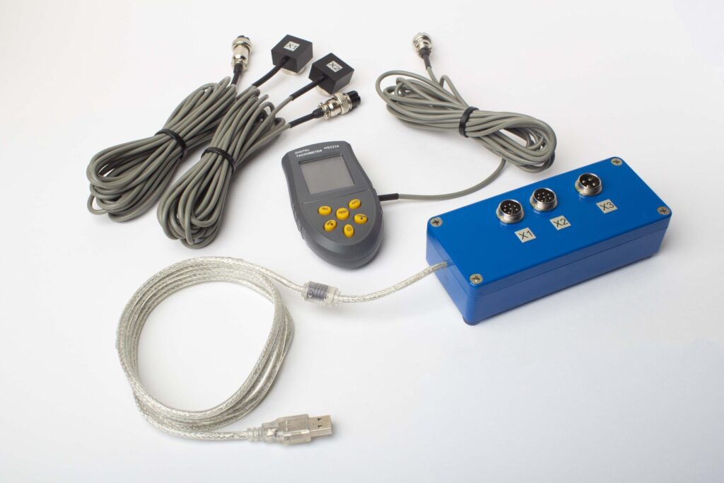
ਪੂਰੇ ਕਿੱਟ ਵਿੱਚ ਕੀ ਸ਼ਾਮਲ ਹੈ
€1,975 · ਪੂਰਾ ਕਿੱਟ, ਸਟਾਕ ਵਿੱਚ, VAT ਇਨਵੌਇਸ
- ਇੰਟਰਫੇਸ ਮਾਪ ਇਕਾਈ (USB, 2 ਚੈਨਲ)
- ਦੋ ਵਾਈਬ੍ਰੇਸ਼ਨ ਐਕਸੇਲੇਰੋਮੀਟਰ (4 m ਕੇਬਲ, 10 m ਵਿਕਲਪਿਕ)
- ਲੇਜ਼ਰ ਟੈਕੋਮੀਟਰ / ਆਪਟੀਕਲ ਫੇਜ਼ ਸੈਂਸਰ (50–500 mm)
- ਸੈਂਸਰ ਲਈ ਮੈਗਨੈਟਿਕ ਸਟੈਂਡ
- ਟਰਾਇਲ & ਸੁਧਾਰ ਵਜ਼ਨ ਲਈ ਡਿਜੀਟਲ ਸਕੇਲ
- Windows ਬੈਲੇਂਸਿੰਗ & ਵਿਸ਼ਲੇਸ਼ਣ ਸੌਫ਼ਟਵੇਅਰ
- ਪਲਾਸਟਿਕ ਟਰਾਂਸਪੋਰਟ ਕੇਸ
ਪੂਰੀ ਕਿੱਟ
ਯੂਨਿਟ · 2 ਸੈਂਸਰ · ਲੇਜ਼ਰ ਟੈਕੋਮੀਟਰ · ਮੈਗਨੈਟਿਕ ਸਟੈਂਡ · ਡਿਜੀਟਲ ਸਕੇਲ · ਸਾਫਟਵੇਅਰ · ਟ੍ਰਾਂਸਪੋਰਟ ਕੇਸ। ਬੈਲੰਸਿੰਗ ਸ਼ੁਰੂ ਕਰਨ ਲਈ ਬਾਕਸ ਵਿੱਚੋਂ ਸਭ ਕੁਝ ਲੋੜੀਂਦਾ।
OEM ਸੈੱਟ
ਯੂਨਿਟ · 2 ਸੈਂਸਰ · ਲੇਜ਼ਰ ਟੈਕੋਮੀਟਰ · ਸਾਫਟਵੇਅਰ। ਉਹਨਾਂ ਇੰਟੀਗ੍ਰੇਟਰਾਂ ਲਈ ਜਿਨ੍ਹਾਂ ਕੋਲ ਪਹਿਲਾਂ ਹੀ ਸਟੈਂਡ, ਸਕੇਲ ਅਤੇ ਕੇਸ ਹੈ, ਜਾਂ ਜੋ ਯੂਨਿਟ ਨੂੰ ਬੈਲੇਂਸਿੰਗ ਮਸ਼ੀਨ ਵਿੱਚ ਸ਼ਾਮਲ ਕਰਦੇ ਹਨ।
| ਪੈਰਾਮੀਟਰ | ਮੁੱਲ |
|---|---|
| ਮਾਪ ਚੈਨਲ | 2 (ਸਿੰਗਲ- & ਟੂ-ਪਲੇਨ ਬੈਲੇਂਸਿੰਗ) |
| ਵਾਈਬ੍ਰੇਸ਼ਨ ਵੇਲੋਸਿਟੀ ਰੇਂਜ | 0.2–80 mm/s RMS |
| ਫ੍ਰੀਕੁਐਂਸੀ ਰੇਂਜ | 5–1000 Hz (550 Hz ਤੋਂ ਉੱਪਰ ≤10% ਐਂਪਲੀਟਿਊਡ ਗਲਤੀ) |
| ਮਾਪ ਸ਼ੁੱਧਤਾ | ਪੂਰੇ ਸਕੇਲ ਦਾ ±5% |
| ਵਿਧੀ | 3-ਰਨ ਇਨਫਲੂਐਂਸ-ਕੋਏਫੀਸ਼ੀਐਂਟ (1 ਜਾਂ 2 ਸੁਧਾਰ-ਪਲੇਨ) |
| ਵਿਸ਼ਲੇਸ਼ਣ | 1× 'ਤੇ ਐਂਪਲੀਟਿਊਡ & ਫੇਜ਼, FFT ਸਪੈਕਟ੍ਰਮ & ਵੇਵਫਾਰਮ, ਸੰਭਾਲੀਆਂ ਗਈਆਂ ਰਿਪੋਰਟਾਂ |
| ਲੈਪਟਾਪ | ਸ਼ਾਮਲ ਨਹੀਂ (Windows PC, ਬੇਨਤੀ 'ਤੇ ਉਪਲਬਧ) |
ਫੀਲਡ ਬੈਲੇਂਸਿੰਗ ਬਨਾਮ ਬੈਲੇਂਸਿੰਗ ਮਸ਼ੀਨ — ਕਿਹੜਾ ਸਹੀ ਹੈ?
ਦੋਵੇਂ ਢੰਗ ਸਹੀ ਨਤੀਜੇ ਦਿੰਦੇ ਹਨ, ਪਰ ਇਹ ਵੱਖ-ਵੱਖ ਸਥਿਤੀਆਂ ਲਈ ਢੁਕਵੇਂ ਹਨ। ਫੈਸਲਾ ਕਰਨ ਲਈ ਇਸ ਸਾਰਣੀ ਦੀ ਵਰਤੋਂ ਕਰੋ:
| ਫੈਕਟਰ | ਫੀਲਡ ਬੈਲੇਂਸਿੰਗ (Balanset-1A) | ਬੈਲੇਂਸਿੰਗ ਮਸ਼ੀਨ (ਵਰਕਸ਼ਾਪ) |
|---|---|---|
| ਸ਼ਾਫਟ ਹਟਾਉਣਾ ਲੋੜੀਂਦਾ | ਨਹੀਂ | ਹਾਂ |
| ਸਥਾਪਿਤ ਅਲਾਈਨਮੈਂਟ ਨੂੰ ਧਿਆਨ ਵਿੱਚ ਰੱਖਦਾ ਹੈ | ਹਾਂ | ਨਹੀਂ |
| ਮੌਕੇ ’ਤੇ, ਵਾਹਨ ਦਾ ਕੋਈ ਡਾਊਨਟਾਈਮ ਨਹੀਂ | ਹਾਂ | ਨਹੀਂ |
| ਦੋ-ਪਲੇਨ ਇੱਕੋ ਸਮੇਂ ਸੁਧਾਰ | ਹਾਂ | ਹਾਂ |
| ISO 21940-11 ਪਾਲਣਾ ਰਿਪੋਰਟ | ਹਾਂ | ਹਾਂ |
| ਲੰਬੇ/ਭਾਰੀ ਡਰਾਈਵਸ਼ਾਫਟਾਂ ਲਈ ਸਭ ਤੋਂ ਵਧੀਆ | ਹਾਂ | ਸੰਭਵ |
| ਬਹੁਤ ਉੱਚ ਸਟੀਕਤਾ (<G1) ਲਈ ਸਭ ਤੋਂ ਵਧੀਆ | ਸੰਭਵ | ਹਾਂ |
| ਪੋਰਟੇਬਲ (ਕਈ ਮਸ਼ੀਨਾਂ ’ਤੇ ਵਰਤੋਂ) | ਹਾਂ | ਨਹੀਂ |
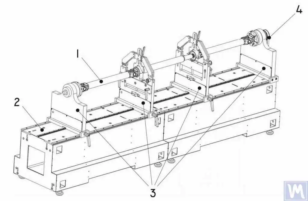
ਅਸਲ ਡਰਾਈਵਸ਼ਾਫਟ-ਬੈਲੰਸਿੰਗ ਮਾਮਲੇ
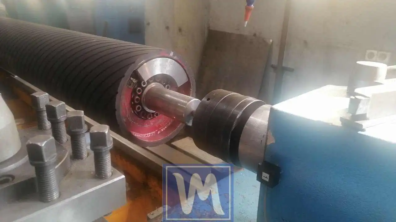
ਡਰਾਈਵ ਸ਼ਾਫਟ ਬੈਲੰਸਿੰਗ
ਇੱਕ ਉਦਯੋਗਿਕ ਡਰਾਈਵ ਸ਼ਾਫਟ ਦੀ ਦੋ-ਪਲੇਨ ਫੀਲਡ ਬੈਲੰਸਿੰਗ, ਸਪੀਡ-ਨਿਰਭਰ ਵਾਈਬ੍ਰੇਸ਼ਨ ਨੂੰ ਖਤਮ ਕਰਨਾ ਅਤੇ U-ਜੋੜ ਦੇ ਲੋਡ ਨੂੰ ਘਟਾਉਣਾ।
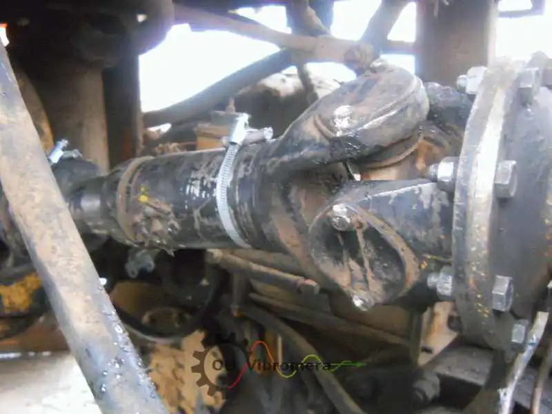
ਵਾਹਨ ਵਿੱਚ ਡਰਾਈਵਸ਼ਾਫਟ
ਪ੍ਰੌਪਸ਼ਾਫਟ ਨੂੰ ਵਾਹਨ ਦੇ ਹੇਠਾਂ ਸੜਕ ਦੀ ਸਪੀਡ ’ਤੇ, ਡਰਾਈਵਲਾਈਨ ਤੋਂ ਚੁੱਕੇ ਬਿਨਾਂ ਹੀ ਬੈਲੰਸ ਕੀਤਾ ਗਿਆ।
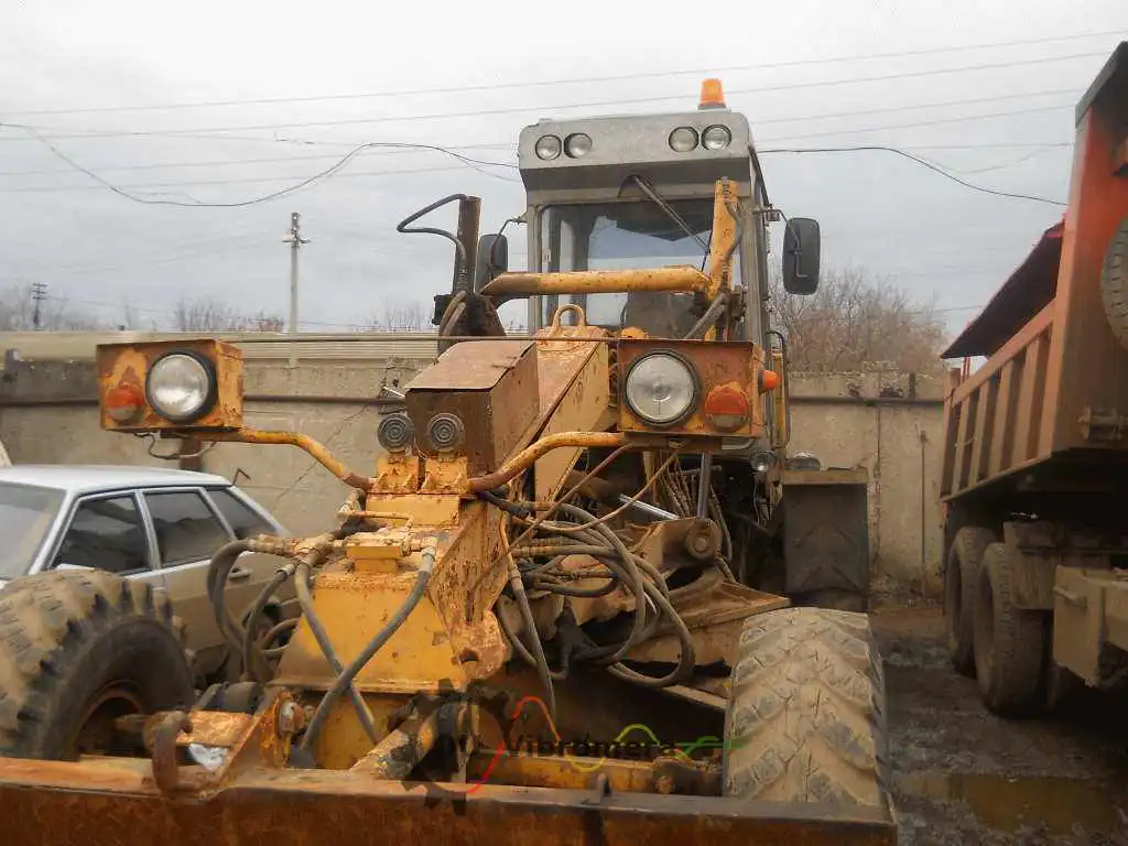
ਮੋਟਰ ਗ੍ਰੇਡਰ ’ਤੇ ਕਾਰਡਨ
ਕਾਰਡਨ ਸ਼ਾਫਟ ਨੂੰ ਸਿੱਧਾ ਇੱਕ ਕੰਮ ਕਰ ਰਹੇ ਮੋਟਰ ਗ੍ਰੇਡਰ ’ਤੇ ਬੈਲੰਸ ਕੀਤਾ ਗਿਆ, ਮਸ਼ੀਨ ਦੇ ਡਾਊਨਟਾਈਮ ਤੋਂ ਬਿਨਾਂ ਕੈਬ ਵਾਈਬ੍ਰੇਸ਼ਨ ਨੂੰ ਠੀਕ ਕੀਤਾ।
ਰਬੜਾਈਜ਼ਡ ਸ਼ਾਫਟ
ਲੇਥ ’ਤੇ ਰਬੜ-ਲਾਈਨਡ ਟ੍ਰਾਂਸਮਿਸ਼ਨ ਸ਼ਾਫਟਾਂ ਦੀ ਡਾਇਨਾਮਿਕ ਬੈਲੰਸਿੰਗ, G2.5 ਸਹਿਣਸ਼ੀਲਤਾ ਪ੍ਰਾਪਤ ਕਰਨਾ।
ਮੁਫ਼ਤ ਡਰਾਈਵਸ਼ਾਫਟ ਕੈਲਕੁਲੇਟਰ
ਡਰਾਈਵਸ਼ਾਫਟ ਬੈਲੰਸਿੰਗ FAQ
ਕੀ ਤੁਸੀਂ ਪ੍ਰੌਪਸ਼ਾਫਟ ਨੂੰ ਵਾਹਨ ਤੋਂ ਹਟਾਏ ਬਿਨਾਂ ਬੈਲੰਸ ਕਰ ਸਕਦੇ ਹੋ?
ਡਰਾਈਵਸ਼ਾਫਟ ਨੂੰ ਹਮੇਸ਼ਾ ਦੋ-ਪਲੇਨ ਬੈਲੰਸਿੰਗ ਦੀ ਲੋੜ ਕਿਉਂ ਹੁੰਦੀ ਹੈ?
ਮੇਰੇ ਪ੍ਰੌਪਸ਼ਾਫਟ ਨੂੰ ਇੱਕ ਨਵੇਂ OEM ਹਿੱਸੇ ਨਾਲ ਬਦਲਿਆ ਗਿਆ ਸੀ ਪਰ ਵਾਈਬ੍ਰੇਸ਼ਨ ਅਜੇ ਵੀ ਮੌਜੂਦ ਹੈ। ਕਿਉਂ?
ਕੀ ਉਹੀ ਟੂਲ ਫਲਾਈਵ੍ਹੀਲ ਜਾਂ ਪੁਲੀ ਨੂੰ ਬੈਲੰਸ ਕਰ ਸਕਦਾ ਹੈ?
ਖੇਤੀਬਾੜੀ ਅਤੇ ਨਿਰਮਾਣ ਮਸ਼ੀਨਰੀ ਸ਼ਾਫਟਾਂ ’ਤੇ ਕਿਹੜਾ ਬੈਲੰਸ ਗ੍ਰੇਡ ਲਾਗੂ ਹੁੰਦਾ ਹੈ?
ਇਨ-ਸਿਟੂ ਡ੍ਰਾਈਵਸ਼ਾਫ਼ਟ ਬੈਲੇਂਸਿੰਗ ਵਿੱਚ ਕਿੰਨਾ ਸਮਾਂ ਲੱਗਦਾ ਹੈ?
ਸਿਧਾਂਤ ਸਿੱਖੋ
ਆਪਣੇ ਡ੍ਰਾਈਵਸ਼ਾਫ਼ਟ ਨੂੰ ਬੈਲੇਂਸ ਕਰੋ — ਥਾਂ 'ਤੇ, ਸਪੀਡ 'ਤੇ
Balanset-1A ਵਾਹਨ ਹਟਾਏ ਬਿਨਾਂ ਦੋ-ਪਲੇਨ ਕਾਰਡਨ-ਸ਼ਾਫ਼ਟ ਅਤੇ ਪ੍ਰੌਪਸ਼ਾਫ਼ਟ ਬੈਲੇਂਸਿੰਗ ਸੰਭਾਲਦਾ ਹੈ, ਦੋਵਾਂ ਸਿਰਿਆਂ ਲਈ ਇੱਕੋ ਸਮੇਂ ਕਰੈਕਸ਼ਨ ਵੇਟ ਦੀ ਗਣਨਾ ਕਰਦਾ ਹੈ, ਅਤੇ ਨਤੀਜੇ ਨੂੰ ISO 21940-11 ਅਨੁਸਾਰ ਦਸਤਾਵੇਜ਼ੀਕਰਨ ਕਰਦਾ ਹੈ। ਪੋਰਟੇਬਲ, ਸੰਪੂਰਨ, ਬਾਕਸ ਤੋਂ ਬਾਹਰ ਵਰਤੋਂ ਲਈ ਤਿਆਰ।
