认识 Vibromera.com —— 我们全新的国际网站。 访问 Vibromera.com →
场平衡 · 完整指南

动态轴平衡平衡说明: 静态与动态, 现场操作规程和 ISO 21940 等级

现场工程师进行转子现场动平衡所需的一切内容——从不平衡的物理原理到最终验证运行。包含七步操作流程、试重公式、校正角测量以及 ISO 公差表。基于 Vibromera 在风机、林业粉碎机、破碎机和轴类设备上的现场工作经验。

✎ Nikolai Shelkovenko 更新日期:2026年2月 阅读时间约18分钟

什么是动态平衡?

定义

动态平衡 动平衡是指在旋转体(转子)以工作转速旋转时,测量并校正其质量分布不均的过程。与校正单个平面内质量偏移的静态平衡不同,动态平衡解决的是多个平面上的不平衡问题。 两个或多个飞机同时, 消除了引起轴承振动的离心力和摇摆力矩。

从200公斤重的粉碎机转子到5克重的牙科钻轴,所有旋转部件都存在一定的残余不平衡。制造公差、材料不一致性、腐蚀和沉积物都会使质心偏离几何旋转轴。其结果是产生离心力,该离心力与转速的平方成正比:转速翻倍,离心力则增加四倍。

转子以 3000 转/分的速度旋转,在 150 毫米半径处仅有 10 克的不平衡量,就会产生约 150 牛顿的旋转力——足以在几周内损坏轴承。动态平衡可以将这种力降低到国际标准(ISO 21940-11,原 ISO 1940)规定的水平,从而将轴承寿命从几个月延长到几年,并减少振动引起的停机时间。

现场工程师笔记
在我13年的现场工作中,大约40%起振动投诉的根本原因都是不平衡造成的。这也是最容易现场修复的故障——训练有素的技术人员使用合适的仪器,无需拆卸转子,即可在30-45分钟内完成维修。

静态平衡与动态平衡

单平面
转子静不平衡——重心向下旋转
静态平衡

转子的重心偏离旋转轴。 一个平面. 当放置在刀刃状支架上时,较重的一侧会滚到底部——即使不旋转也能察觉到这一点。

更正: 在与重物点相对的单个角度位置上增加或移除质量。一个修正平面就足够了。

适用于 L/D 低于约 0.5 的狭窄盘状部件,例如飞轮、砂轮、单盘叶轮、锯片、制动盘。

两架飞机
长转子处于动态不平衡状态——两个质量偏移位于不同的平面上
动态平衡

两个(或更多)质量偏移位于 不同的平面 沿转子长度方向。它们在静态情况下可能会相互抵消——转子静止地位于刀刃上——但会产生一个 摇滚情侣 旋转时。如果不旋转,就无法检测或纠正这种相互作用。

更正: 两个补偿配重分别位于两个不同的平面上。该仪器根据影响系数矩阵计算每个平面上的质量和角度。

适用于 细长转子——轴、宽叶轮风扇、粉碎机转子、滚筒、多级泵叶轮、涡轮机。

主要区别: 即使是静态平衡的转子,也可能存在严重的动态不平衡。一个平面内的力与另一个平面内的力方向完全相反,因此转子不会在支撑件上滚动——但一旦旋转起来,这种力偶就会在轴承处产生剧烈振动。双平面动态平衡可以弥补静态平衡方法的不足。

四种失衡类型

ISO 21940-11区分了四种基本的不平衡模式。了解哪种模式占主导地位有助于选择正确的平衡策略。

静态
单个重点。重心偏离旋转轴。静止时可检测到。单平面校正。
力偶
两个质量相等的物体,相隔 180°,位于不同的平面上。合力为 0,但会产生力矩(力偶)。静止时不可见。
准静态
静力矩与力偶的组合,其中主惯性轴与旋转轴相交于重心以外的点。
动态
一般情况:主惯性轴既不与旋转轴相交也不平行。这是现实世界中最常见的情况。必须进行双平面修正。

实际上,几乎所有现场遇到的转子都存在动态不平衡——力和力矩分量的组合。因此,对于非薄盘状转子,双平面平衡是默认的平衡方法。

何时使用单平面平衡法与双平面平衡法

决定性因素是转子的 几何比长径比 (轴向长度与外径之比)及其运行速度。

标准 单平面(1个传感器) 双平面(2个传感器)
升/直径比 L/D < 0.5(狭窄盘状转子) L/D >= 0.5,或轴向质量分布显著
典型部件 砂轮、飞轮、单盘叶轮、皮带轮、制动盘、锯片 风扇转子、粉碎机、轴、滚筒、多级泵、涡轮机、破碎机
不平衡类型已纠正 仅静态(力) 静力 + 力偶 + 动力(力 + 力矩)
校正平面 1 2
测量运行 2(初始 + 1 次试验) 3(初始 + 2 次试验,每个平面一次)
现场停留时间 15-20分钟 30-45分钟
经验法则
如果两个校正平面的间距小于转子轴承跨距的大约三分之一,平面之间的交叉耦合会很强,单平面平衡可能会在远端轴承处留下较大的残余不平衡。应尽可能增大平面间距;如果您使用的是双通道仪器,对于细长转子应采用双平面平衡。

ISO 21940-11 平衡质量等级

ISO 21940-11(ISO 1940-1 的后续标准)对每一类旋转机械进行分类。 平衡质量等级 G, 定义为转子重心的最大允许速度,单位为毫米/秒。允许的残余比不平衡 e (单位为g·mm/kg)由料级和运行速度计算得出:

允许的具体不平衡
e = G × 1000 / ω = G × 1000 / (2π × 转速 / 60)
e — 允许的残余比失重,g·mm/kg
G — 平衡质量等级(例如 6.3 表示 6.3 毫米/秒)
ω — 角速度,弧度/秒
转速 — 运行速度,转/分钟
等级 e·ω,毫米/秒 机器类型
G 0.4 0.4 陀螺仪,精密磨床主轴
G 1.0 1.0 Turbochargers, small electric armatures with special requirements
G 2.5 2.5 Electric motors and generators with special requirements (ordinary industrial motors are G 6.3), medium/large turbines, pumps
G 6.3 6.3 风机、泵、工艺机械、飞轮、离心机、通用工业机械
G 16 16 农业机械、破碎机、传动轴(万向轴)、破碎机零部件
G 40 40 乘用车车轮、曲轴总成(批量生产)
G 100 100 六缸及以上的高速柴油发动机曲轴总成

实例:风扇转子

离心风扇转子重 80 kg,转速为 1,450 RPM,修正半径为 250 mm。所需等级:G 6.3。

计算
e = 6.3 × 1000 / (2π × 1450 / 60) = 6300 / 151.8 ≈ 41.5 克·毫米/千克
总允许偏差 = 41.5 × 80 = 3,320 克·毫米
修正半径为 250 毫米时:最大残余质量 = 3320 / 250 = 13.3克 残余总质量
对于双平面作业,应将该总公差分配到两个平面;简单平均分配后每个平面约为 每个平面 6.6 g.

相关标准: ISO 21940-11 (刚性转子), ISO 21940-12 (柔性转子), ISO 10816-3 (振动严重程度限值), ISO 1940 (前身).

七步现场平衡程序

这是利用便携式仪器(例如……)进行双平面场平衡的影响系数法。 Balanset-1A. 同样的逻辑也适用于任何双通道平衡分析仪。

Before you balance: make sure unbalance is really the dominant fault. The vibration should be dominated by the 1× (running-speed) component; check that mounting bolts are tight and there is no looseness, rule out shaft misalignment, and verify the machine is not running close to a structural resonance — use the software's 碰撞测试 to find the natural frequencies. Balancing will not cure looseness, misalignment, or a resonance problem.
1
准备转子并安装传感器
清除轴承座上的灰尘和油脂——传感器必须与金属表面齐平。将振动传感器 1 安装在最靠近轴承座的轴承座上。 飞机 1 (通常是驱动端)。将传感器 2 安装在附近 飞机 2 (非驱动端)。将反光胶带贴在轴上,用于安装激光转速表。将所有电缆连接到测量单元。
2
测量初始振动(运行 0)
In the software, open the balancing wizard — F3 - Two-plane (或 F7 - Balancing) — and start on the Run 0 - Initial tab. Start the rotor and bring it to stable operating speed. The instrument measures vibration amplitude (mm/s) and phase angle (°) at both sensors simultaneously. This is the 基线 — 转子在治疗前的"病症"。记录数值并停止机器。
现场提示:转速稳定后至少等待 10-15 秒再进行记录。最初几秒钟内,热瞬变和气流会逐渐消失。
转子初始振动测量——Balanset-1A屏幕显示基线读数
3
在 1 号平面上安装试验配重(运行 1)
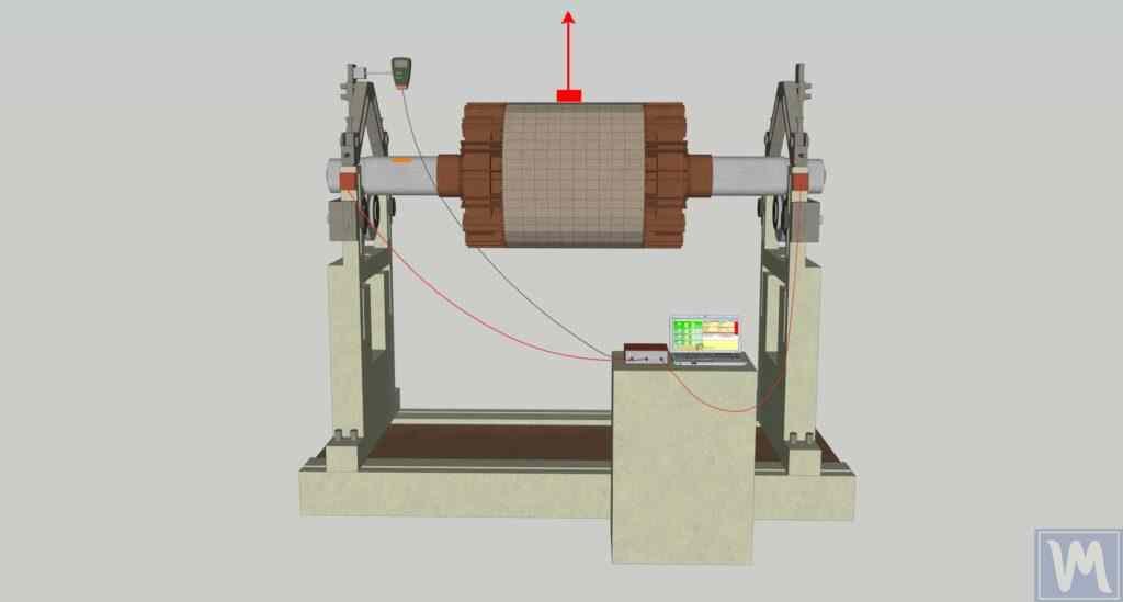
停止转子。安装 试验重量 of known mass at an arbitrary angular position in Plane 1. Mark this position clearly — it becomes your 0° reference for angle measurement later. Enter the trial weight Mass, gRadius, mm in the software's Trial weight group — without the mass entered, the program can only report the correction as a percentage of the trial weight. Switch to the Run 1 - Trial Pl.1 tab, restart the rotor and record vibration at both sensors. The instrument now knows how the rotor's vibration field changes when mass is added in Plane 1.
Field tip: Use a bolt with a washer clamped to the rotor rim, or a hose clamp with a nut for quick attachment. The trial weight should produce a measurable vibration change (20–30% amplitude change or 20–30° phase shift at either sensor).
试验用砝码应该有多重? 使用经验公式: Mt = Mr × Ksupport × Kvibration / (Rt × (N/100)²) 其中 Mr = rotor mass (g), Ksupport = support stiffness coefficient (0.5–5.0, use 3 for standard pedestals), K振动 = vibration level coefficient (0.5–3.0, use 1.0 for normal vibration of 5–10 mm/s), Rt = 安装半径(厘米),N = 转速。或者使用我们的 在线试用体重计算器 — 输入转子参数,即可立即获得推荐质量。
在第一校正平面上安装校准砝码
4
将试验重量移至平面 2(运行 2)
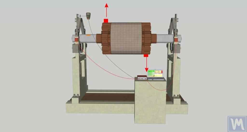
Stop the rotor. Remove the trial weight from Plane 1. Attach the same trial weight (or one of similar known mass) at an arbitrary position in Plane 2. Mark this second reference point. Switch to the Run 2 - Trial Pl.2 tab, restart and record vibration at both sensors. Now the instrument has the complete influence coefficient matrix — four complex coefficients linking unbalance in either plane to vibration at either sensor.
现场提示:如果您在 Plane 2 中使用不同的试验砝码质量,请在软件中输入正确的值 - 计算会自动调整。
将试验重量移至第二个校正平面,进行第二次试验。
5
计算校正权重
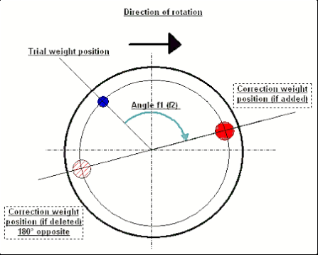
The instrument solves the influence coefficient equations and displays the Correction mass (g)Angle (°) for Plane 1 and Plane 2. The angle is measured from the trial weight position in the direction of rotor rotation. In the Correction method group you choose Add mass (weld or bolt a counterweight) or Remove mass (drill or grind material). The displayed angle is always the angle you actually work at: with Remove mass selected the software has already added 180° to the computed angle, so drill or remove exactly where it indicates — do not add another 180°.
6
安装校正配重块
Remove the trial weight from Plane 2. Fabricate or select correction weights matching the calculated masses. Install each correction weight at the same radius as the trial weight — the calculated mass is valid only at that radius. If you must use a different radius, enter both radii in the software so it recalculates the mass. Measure the angle from the trial weight reference mark in the direction of rotation. Attach the correction weights firmly — welding, hose clamps, set‑screw weights, or bolts depending on the machine type and speed.
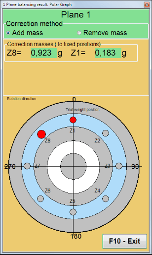
Field tip: If you cannot place a weight at the exact angle (e.g. only bolt holes available), use the Weight Installing Method setting — Free positions, Fixed positions, Circular groove, or Drill. With Fixed positions the instrument decomposes the correction vector into two components at the nearest available positions.
图示为校正重量角度测量——从试验重量位置沿旋转方向测量。
7
核对余额(支票运行)
Restart the rotor and record the final vibration. Compare against the initial baseline and against the ISO 21940‑11 tolerance for your machine class — enter the tolerance in the Balancing tolerance, g*mm field, or press the ISO 1940... button to calculate it from the G‑grade, rotor mass, and RPM (divide the g·mm result by the correction radius to get grams). If vibration is within specification, you are done. If not, the instrument can perform a 微调运行 on the Run T - Trim tab — it uses the existing influence coefficients to calculate a small additional correction without new trial weights.
现场提示:通常一次修剪就足够了。如果需要修剪两次以上,说明两次修剪之间可能出现了变化——检查是否有松动的配重、热膨胀或速度变化。
最终验证运行结果显示,平衡后振动水平显著降低。
七个步骤——一种乐器
Balanset-1A 会在屏幕上引导您完成整个双平面测量流程。产品包含两个加速度计、激光转速计、Windows 软件和便携箱。
€1,975
查看 Balanset‑1A WhatsApp

试验重量计算

The trial weight must be heavy enough to produce a noticeable vibration change, but light enough not to overload bearings or create a dangerous condition. The standard empirical formula accounts for rotor mass, correction radius, operating speed, support stiffness, and the measured vibration level:

试验体重公式
Mt = Mr × Ksupport × K振动 /(Rt × (N / 100)²
Mt — 试验重量,克
Mr —转子质量,克
Ksupport — support stiffness coefficient (0.5–5.0: 1 = soft rubber mounts, 2–3 = standard bearing pedestals, 4–5 = massive rigid foundation)
K振动 — vibration level coefficient (0.5–3.0: 0.5 = up to 5 mm/s, 1.0 = 5–10 mm/s, 1.5 = 10–20 mm/s, 2.0 = 20–40 mm/s, 2.5–3.0 = above 40 mm/s)
Rt — 试验重量安装半径,厘米
N — 运转速度,RPM

不想手动计算?使用我们的 在线试用体重计算器↗ — 输入转子参数、支撑类型和振动水平,即可立即获得推荐的质量。

Worked Examples (Ksupport = 3, K振动 = 1.0)

机器 转子质量 转速 半径 Trial weight (K支撑 = 3, K振动 = 1)
粉碎机转子 120公斤 2,200 30厘米 360,000 / (30 × 484) ≈ 25克
工业风扇 80公斤 1,450 40厘米 240,000 / (40 × 210.25) ≈ 29克
离心机滚筒 45公斤 3,000 15厘米 135,000 / (15 × 900) = 10克
破碎机轴 250公斤 900 25厘米 750,000 / (25 × 81) ≈ 370克

Values shown assume Ksupport = 3 (standard bearing pedestals) and K振动 = 1.0 (normal vibration of 5–10 mm/s); scale accordingly for other support and vibration conditions.

实用技巧:验证响应
The formula gives the minimum trial mass that should produce a measurable response. After the trial run, check that the phase shifted by at least 20–30° and the amplitude changed by 20–30%. If the response is too small, double or triple the trial mass and repeat. At very low RPM (< 500), the formula may yield impractically large values — instead size the trial weight so that its centrifugal force is about 10% of the rotor weight: m = 0.1 × Mr × 9.81 / (ω² × r), with m and Mr in kg, ω in rad/s and r in meters.

校正角度测量

平衡仪每个平面输出两个数值: 质量 (重量)和 角度 (放置位置)。角度始终以试重位置为参考。
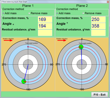
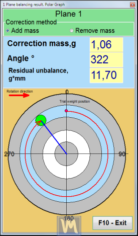
Balanset-1A 软件——双平面平衡结果窗口,在极坐标图上显示修正砝码的质量和角度。
Balanset‑1A result screen: the software calculates the correction for each plane and displays it on a polar chart. The blue vector with the green end marker points at the correction weight position; the red rings are the amplitude scale. Here the correction mass is shown in % of the trial weight because the trial mass was not entered — enter Mass, g in the Trial weight group to get grams and residual unbalance in g·mm.

如何测量角度

极坐标图显示校正重量角度相对于试验重量位置
  • 参考点(0°): 放置试验砝码的角度位置。在试运行前,请在转子上清晰标记该位置。
  • 测量方向: 始终沿转子旋转方向。
  • 解读角度: the result window shows the Correction massAngle for each plane. From the trial weight mark, count that many degrees in the rotation direction — that is where the correction weight goes.
  • 如果要切除组织: select Remove mass in the Correction method group — the software adds 180° to the computed angle automatically, so drill or grind exactly at the displayed angle.

将重量分配到固定位置

极坐标图显示重量分配到两个固定螺栓孔位置

When the rotor has pre‑drilled holes or fixed mounting positions (e.g. fan blade bolts), you may not be able to place a weight at the exact calculated angle. In the Balanset‑1A software this is handled by the Weight Installing Method setting, which offers four modes: 自由位置, 固定位置, 圆形凹槽, 和 Drill (material removal, with drilling-depth calculation). With Fixed positions you enter the angles of the two nearest available positions, and the software decomposes the single correction vector into two smaller weights at those positions. The combined effect matches the original vector.

校正平面和传感器放置

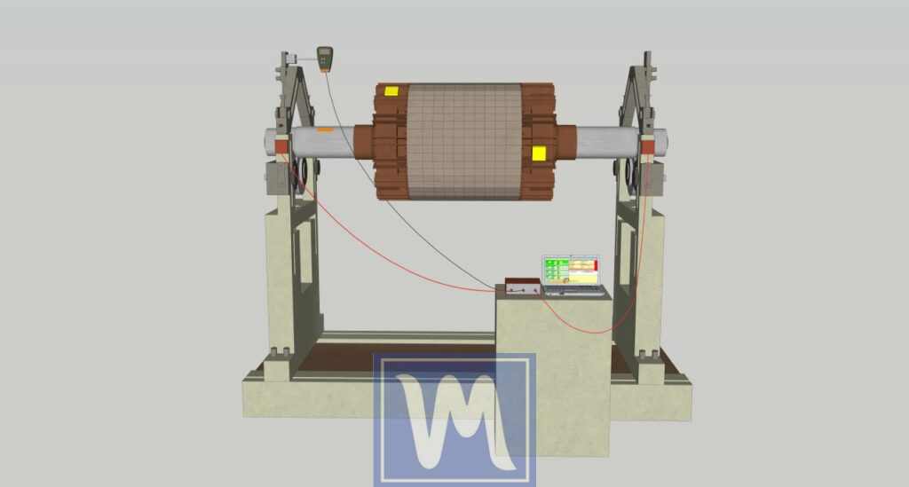
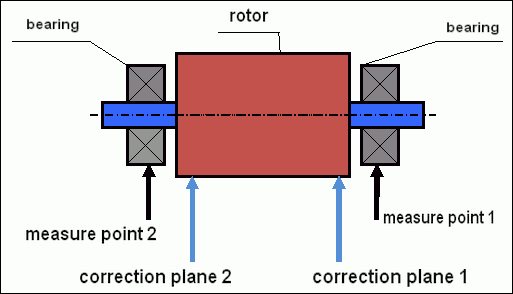
转子上的校正平面和传感器测量点示意图

校正平面是指转子上增加或减少质量的轴向位置。传感器测量最近轴承处的振动。以下是一些关键规则:

  • 传感器安装在轴承座上 — 尽可能靠近轴承中心线,沿径向(最好是水平方向)。
  • 平面 1 对应于传感器 1,, 平面 2 到传感器 2。保持编号一致,否则软件会交换校正平面。
  • 最大程度地拉开平面间距: 两个校正平面之间的距离越大,力偶分辨率越高。最小实际间距为轴承跨距的三分之一。
  • 选择合适的岗位: 校正平面必须是可以在物理上施加重物的位置——法兰边缘、螺栓圆周、轮辋或焊接表面。
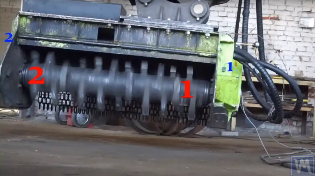
碎枝机转子,显示校正平面(蓝色 1 和 2)和配重安装点(红色 1 和 2)

上图所示为一台碎枝机转子,正准备进行双平面平衡。蓝色标记 1 和 2 指示轴承座上的传感器位置。红色标记 1 和 2 指示校正平面——在本例中,即转子本体的法兰端,配重块将焊接于此。

悬臂式(过伸式)转子

悬臂式转子——例如风扇叶轮、安装在轴承跨距外侧的飞轮以及泵叶轮——需要不同的传感器和校正平面布局。两个校正平面都位于轴承的同一侧,传感器位置必须考虑悬臂质量放大力矩不平衡的影响。
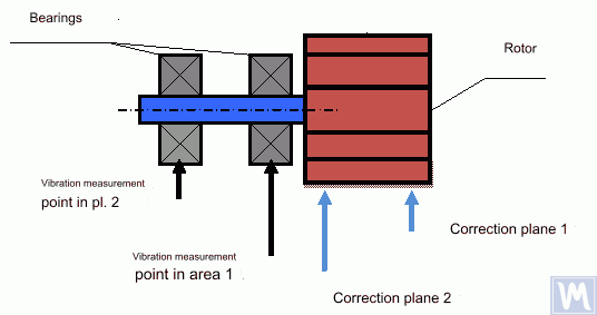
悬臂式转子传感器连接和校正平面布局示意图——Balanset-1A 双平面设置
悬臂转子的传感器连接图:两个校正平面均位于轴承跨距的外侧。
现场悬臂转子动平衡——传感器和校正平面位置标记在实际设备上
现场示例:悬臂转子,传感器和校正平面位置已标记。

按机器类型划分的应用

工业风扇和鼓风机
转速 600–3,600 转/分 · G 6.3 · 双平面
最常见的现场动平衡任务。离心风机、轴流风机、鼓风机。注意叶片上的灰尘积聚——随着时间的推移,灰尘会改变动平衡。清洁或更换叶片后,需要重新进行动平衡。
碎枝机和甩刀式割草机转子
转速 1,800–2,500 转/分 · G 16 · 双平面
重型转子(80–200 公斤),配有可更换的链锤。链锤磨损或更换后会出现不平衡。在转子端法兰处进行两个平面的校正。典型改进:速度从 12 毫米/秒提升至 1 毫米/秒。
破碎机和锤式粉碎机
转速 600–1,200 转/分 · G 16 · 双平面
Extremely heavy rotors (200–1,000+ kg). Trial weights are large — typically 0.3–3 kg by the formula (a 1,000 kg rotor at 600 RPM needs ≈ 3.3 kg). Low RPM means large permissible unbalance — but impact loads and bearing cost still justify balancing.
离心机
转速 1,000–10,000 转/分 · 重力加速度 2.5–6.3 · 双平面
篮式或碟式离心机广泛应用于食品、化工和制药行业。高速运转对精度要求极高。现场平衡可避免长时间的拆卸。检查滚筒内是否有产品堆积。
电动机和发电机
750–3,600 转/分 · G 2.5 · 双平面
电机电枢出厂时已进行平衡,但绕组维修、轴承更换或联轴器更换后需要重新平衡。为获得最佳结果,测试时请将联轴器一半连接在电机上。
联合收割机螺旋钻和转子
400–1,200 转/分 · G 16 · 双平面
长螺旋钻和脱粒转子可清除土壤和作物残茬造成的不平衡。收获前的季节性平衡可防止田间轴承故障。校正配重焊接在叶片上。
水泵叶轮
转速 1,450–3,600 转/分 · G 6.3 · 单平面或双平面
悬臂式叶轮如果宽度较窄,通常只需要进行单平面校正。对于多级泵,每个叶轮在组装前都要在芯轴上单独进行动平衡。
涡轮增压器
30,000–90,000 RPM · G 1.0 · Two‑plane
Ultra‑high speed demands G 1.0 or tighter tolerance. Material removal by grinding — no welded weights at these speeds. Note the instrument limits: the Balanset‑1A covers 250–90,000 RPM and 5–1,000 Hz, with best sensor accuracy below ~550 Hz — service speeds beyond that range are outside its measurement envelope.

重量附加方法

方法 依恋 最适合 限制
焊接 将钢垫圈或钢片点焊到转子轮辋上 粉碎机、破碎机、重型工业转子 永久性。不使用专用杆,无法用于铝或不锈钢。
螺栓和螺母 螺栓穿过预钻孔,并用锁紧螺母固定 风机叶轮、飞轮、联轴器法兰 需要利用现有孔洞或进行新钻孔。
软管夹 带配重的夹式不锈钢软管夹 现场的轴、滚子、圆柱转子 临时或半永久性。检查夹紧扭矩
螺丝夹 预制夹式配重块(例如轮胎配重块) 风扇叶片、薄轮辋、轻型转子 质量范围有限。高转速时可能打滑。
粘合剂(环氧树脂) 配重粘在表面上 精密转子,洁净环境 需要清洁干燥的表面。温度限制约为120°C
材料去除 将材料从较重的一侧钻除或磨除 涡轮增压器、高速主轴、叶轮 永久且精准,但不可逆。适用于增加体重不安全的情况。

场平衡中的常见错误

# 错误 结果 使固定
1 安装在防护罩或盖板上的传感器 盖子的共振会使振幅和相位读数失真 → 导致校正错误 务必安装在轴承座金属表面上。
2 试用重量太轻 相位和振幅变化在噪声范围内 → 影响系数不可靠 确保至少一个传感器的幅值变化达到 20-30%,或相位变化达到 20-30 度
3 跑步间的速度变化 振动频率随转速²变化,即使是5%转速的变化也会破坏数据。 使用转速表精确跟踪转速。等待转速稳定。
4 Leaving the trial weight on without telling the software Correction calculation is skewed by the unaccounted trial weight → result is meaningless Remove the trial weight before installing correction weights — or tick Leave on rotor in the Trial weight group so the software accounts for it
5 混淆了平面 1 和平面 2 校正配重安装位置错误 → 振动加剧 清晰标注传感器和平面。传感器 1 → 平面 1,传感器 2 → 平面 2
6 测量与旋转方向相反的角度 Correction goes 360° − f instead of f → the weight lands mirrored about the reference mark — up to 180° away from the correct position 开始前请确认旋转方向。始终沿旋转方向测量。
7 运行过程中的热增长 冷启动运行期间轴承间隙的变化 → 测量漂移 要么在第 0 次运行前进行热身至稳定状态,要么快速完成所有运行(间隔 <5 分钟)。
8 在长转子上使用单平面 力偶不平衡未得到纠正 → 远端轴承处的振动甚至可能加剧 对于任何 L/D >= 0.5、平面间距显著,或单平面校正会影响远端轴承的转子,都应采用双平面平衡

现场报告:碎枝机转子平衡

真实现场数据 · 2025年2月
连枷式割草机 — Maschio Bisonte 280
振动前
12.4 毫米/秒
振动后
0.8 毫米/秒
减少
93.5%
现场停留时间
38分钟

机器: Maschio Bisonte 280 型旋耕机,转子重 165 公斤,动力输出轴转速 2100 转/分。客户反映更换 8 个刀片后,机器振动剧烈。

设置: 轴承座上装有两个加速度计,动力输出轴上装有一个激光转速计。Balanset-1A 双平面模式。

运行 0: 传感器 1 = 12.4 毫米/秒 @ 47°,传感器 2 = 8.9 毫米/秒 @ 213°。ISO 10816-3 D 区(危险)。

试运行: 两个平面均使用 500 克试验砝码。响应清晰——两个传感器的振幅变化均大于 60%。

Trial mass note: with Ksupport = 3 and K振动 = 1 the trial weight formula suggests only ≈ 37 g for this rotor — the formula result is a minimum, and higher Ksupport/K振动 factors call for heavier weights. The 500 g weight used on this job was well above that minimum; the >60% amplitude response confirmed a valid trial, which is the criterion that actually matters.

更正: 平面 1:340 克,焊接角度 128°。平面 2:215 克,焊接角度 276°。

验证: 传感器 1 = 0.8 毫米/秒,传感器 2 = 0.6 毫米/秒。ISO A 区(良好)。无需微调。

风扇的双平面动态平衡

工业风机——包括离心式、轴流式和混流式风机——是现场最常见的需要进行动平衡的转子之一。以下步骤将指导您使用 Balanset-1A 对一台径向风机进行实际的双平面动平衡作业。

确定平面和安装传感器

安装传感器前,请清除表面污垢和油渍。传感器必须紧密贴合轴承座的金属表面——切勿安装在盖子、防护罩或无支撑的金属板上。

风扇双平面平衡传感器连接图——Balanset-1A 设置,已标记校正平面
悬臂式风扇叶轮的传感器连接和校正平面布局。
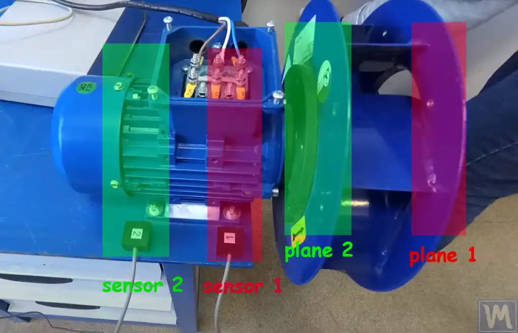
风扇转子,传感器位置和校正平面分别用红色和绿色区域标记。
风扇转子上的传感器和校正平面位置:传感器 1(红色)靠近前方,传感器 2(绿色)靠近后方。
  • 传感器 1(红色): 安装位置靠近风扇前部(平面 1 侧)。
  • 传感器 2(绿色): 安装位置靠近风扇后部(平面 2 侧)。
  • 1号平面(红色区域): 叶轮盘上的修正平面,靠近前端。
  • 平面 2(绿色区域): 校正平面更靠近背板或轮毂。

将两个振动传感器和激光转速表连接到 Balanset‑1A。将反光胶带贴在轴或轮毂上作为转速参考。

平衡过程

启动风扇并进行初始振动测量(运行 0)。在平面 1 的任意位置安装已知质量的试重,运行风扇并记录振动变化(运行 1)。将试重移至平面 2 的任意位置,再次运行风扇并记录(运行 2)。Balanset-1A 软件使用这三次测量结果来计算每个平面的修正质量和角度。
使用 Balanset-1A 对风扇叶轮进行双平面动平衡后,安装修正配重。
在 Balanset-1A 计算出的位置,将修正配重安装在风扇叶轮上。

风扇校正配重角度测量

角度的测量是从试验砝码的位置沿风扇旋转方向进行的——正如文中所述: 校正角度测量 按照上文所述步骤,标记试验砝码的放置位置(0°参考点),然后沿旋转方向计算所示角度,即可找到校正砝码的位置。

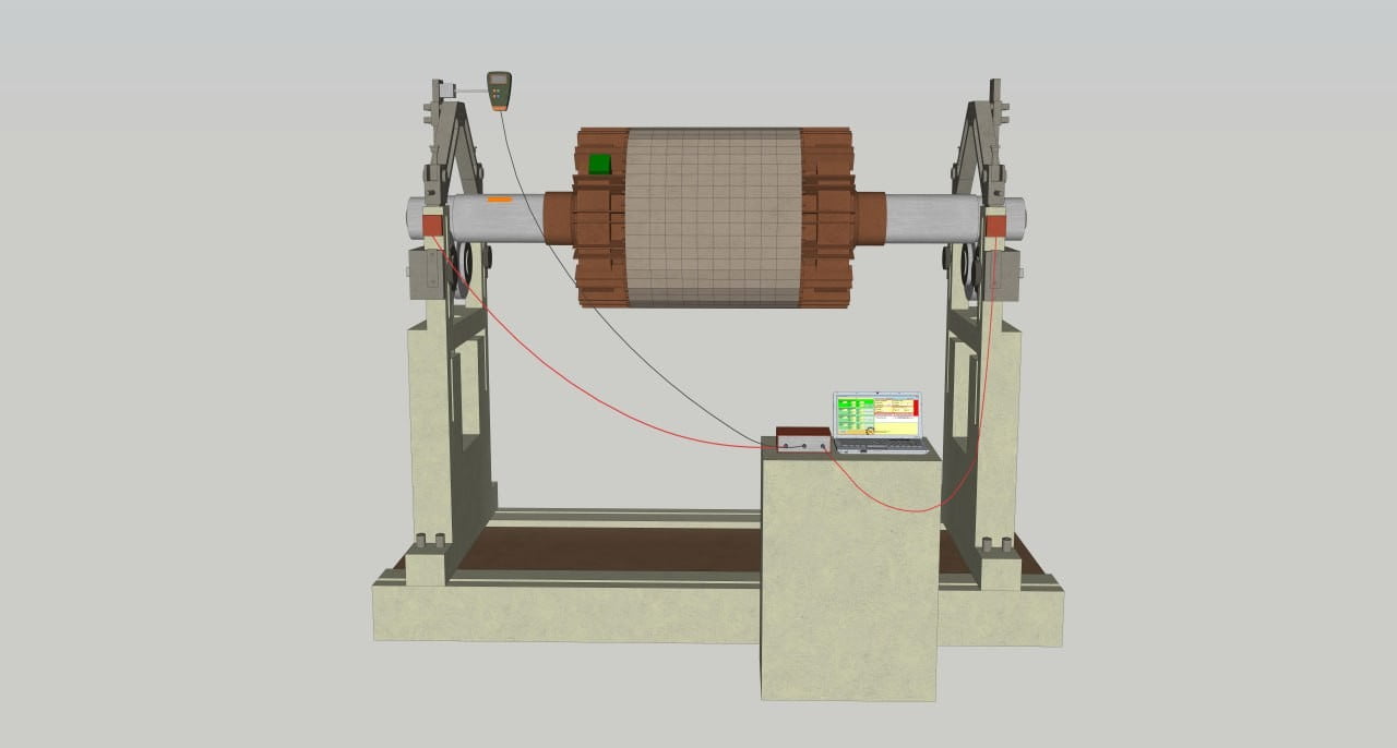
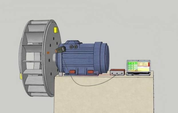
3D illustration of a typical field balancing setup — electric motor with impeller, Balanset-1A measuring unit and laptop
Typical field balancing setup (illustration): vibration sensors on the machine, Balanset‑1A measuring unit, and a laptop running the balancing software.

根据软件计算出的角度和质量,在平面 1 和平面 2 上安装校正配重。再次运行风扇,并确认振动已降至可接受的水平。 ISO 21940-11 (通常通用风扇为 G 6.3)。如果残余振动仍然高于目标值,则进行一次微调运行。

常见问题

Static balancing corrects unbalance in a single plane — the rotor's centre of gravity is shifted back to the rotation axis. It works for narrow, disc-shaped parts where the length-to-diameter ratio L/D is below about 0.5. Dynamic balancing corrects unbalance in two planes simultaneously, addressing both force and couple unbalance. It is required for any elongated rotor where masses are distributed along the shaft length. A rotor can be statically balanced yet dynamically unbalanced — the couple component is invisible until the rotor spins.
使用公式:Mt = Mr × Ksupport × K振动 / (Rt × (N/100)²), where M is in grams, R in cm, and N in RPM. Ksupport is the support stiffness coefficient (0.5–5.0: 1 = soft, 3 = average, 5 = rigid) and K振动 is the vibration level coefficient (0.5–3.0, 1.0 for normal vibration of 5–10 mm/s). The goal is to produce at least 20–30% amplitude change or 20–30° phase shift. Or skip the maths and use our 在线试用体重计算器. At speeds below 500 RPM the formula becomes impractical — instead size the trial weight so its centrifugal force is about 10% of the rotor weight: m = 0.1 × Mr × 9.81 / (ω² × r), with m and Mr in kg, ω in rad/s and r in meters.
Use single-plane for narrow disc-shaped rotors with L/D below about 0.5 — flywheels, grinding wheels, saw blades. Use two-plane for anything longer: shafts, fan impellers, mulcher rotors, rollers, multi-stage pump assemblies. When in doubt, always choose two-plane — it catches couple unbalance that single-plane misses, and only adds one extra measurement run (about 10 minutes).
ISO 21940-11:2016 是目前刚性转子的标准,它取代了 ISO 1940-1:2003。该标准定义了平衡质量等级,从 G 0.4(陀螺仪)到 G 4000(低速船用柴油机曲轴)。常用等级包括:G 6.3 用于风扇和水泵,G 2.5 用于电动机,G 1.0 用于涡轮增压器转子,G 16 用于农业机械和破碎机。平衡等级乘以角速度即可得到最大允许重心速度(单位为毫米/秒),由此可以计算出校正半径处的允许残余质量。
The instrument calculates the correction angle relative to the trial weight position. Mark where you placed the trial weight — this is your 0° reference. Then measure the indicated angle in the direction of rotor rotation from that reference point. The correction weight goes at the resulting position. If you select Remove mass in the Correction method group, the software adds 180° to the computed angle automatically — drill or grind exactly at the displayed angle. Use a protractor or divide the circumference into marked segments before starting.
是的——这叫做现场动平衡或原位动平衡。您需要在轴承座上安装振动传感器,连接转速表参考点,然后让机器以运行速度运转。像 Balanset-1A 这样的便携式仪器会引导您完成试重步骤并计算修正值。现场动平衡可以节省数小时的拆卸时间,消除重新安装造成的对准误差,并在实际运行条件下平衡转子——包括联轴器、热膨胀和实际轴承刚度的影响。

现场平衡设备

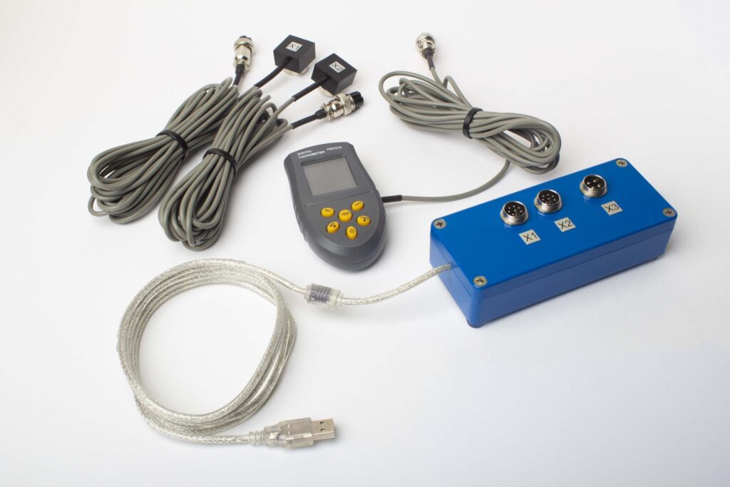
Balanset-1A 是一款双通道便携式仪器,可进行单平面和双平面动平衡,以及振动分析(整体速度、频谱、波形)。它以完整套件的形式发货:

  • 2 个带磁性安装座的 MEMS 振动传感器(基于 ADXL335 的加速度计)
  • 带反光胶带的激光转速表(非接触式转速传感器)
  • USB测量单元(可连接至任何Windows笔记本电脑)
  • 软件:平衡向导、振动计、频谱分析仪
  • 包含所有线缆和配件的便携箱

RPM range: 250-90,000. Vibration range: 0.2-80 mm/s RMS. Frequency range: 5-1000 Hz. Phase accuracy: ±1°. Weight splitting, trim runs, tolerance checking, and report generation included in the software. Full kit weighs approximately 4 kg.

Balanset‑1A — 便携式平衡器和振动分析仪
双通道,双平面,一台仪器即可完成现场平衡、振动测量和 ISO 公差验证。
€1,975
立即订购 请通过 WhatsApp 询问
Balanset-1A 便携式平衡仪和振动分析仪——包含传感器、转速表和便携箱的完整套装
NS
Nikolai Shelkovenko
Vibromera公司首席执行官兼现场工程师
拥有超过13年的振动诊断和现场平衡经验。曾在20多个国家亲自平衡过2000多个转子,涉及的机械包括粉碎机、风扇、破碎机、离心机和联合收割机。

0 Comments

发表回复

Avatar placeholder
WhatsApp
Balanset-1A - 1975 欧元询问工程师