← Balanset-1A teadmistebaas — kõik peatükid
See eeldab, et masin on ette valmistatud vastavalt peatükk 04: laagrid lõtguta, klapid keevitatud, andurid ja takomeeter paigaldatud, näidud stabiilsed.
Tarkvara seadistus
- Loo/vali rootor programmi andmebaasis.
- Valige režiim: 1 või 2 tasandit.
- Täida — kohustuslik:
- katseraskuse mass (kaalu see!);
- raskuse kinnitusraadius (jäta tühjaks ja tulemused tulevad protsentides, mitte grammides);
- g (grammid) lüliti, mitte %;
- korrektsioonimeetod: lisa raskus (keevitamine) või eemalda materjali (puurimine). Kontrolli märkeruutu, sest see määrab tulemuse märgi;
- keskmistuste arv: 8 kiireks ülevaateks, 32–64 tasakaalustamiseks (mida rohkem masin väriseb, seda rohkem).
- Raskuse paigaldusmeetod: vabad asukohad (suvaline nurk), fikseeritud asukohad (labad/poldid — programm jagab raskuse kahe kõrvutise asukoha vahel), ringsoon, puurimine.
Mõõteseeria (2 tasandit)
Run 0 — algne käivitus. Masin valitud pöörete arvul, mõõtmine ilma raskusteta. Märgi üles algsed amplituudid ja faasid (V1o, V2o).
Run 1 — prooviraskus tasandis 1. Peata masin, paigalda katseraskus tasandisse 1 märgitud nurga alla (ükskõik kuhu mugavasse kohta — aga jäta meelde/märgi koht!). Käivita ja mõõda.
- Kontrolli: amplituud või faas muutus 20–30% või rohkem. Kui muutus on väike — raskus on liiga väike, suurenda seda.
Run 2 — katseraskus tasandis 2. Eemalda raskus tasandilt 1 (kui seaded ei ütle “jäta alles”), paigalda tasandile 2, mõõda.
Arvutus. Programm väljastab korrigeeriva raskuse massi ja nurga iga tasandi kohta (M1/F1, M2/F2).
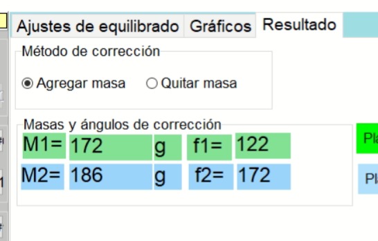
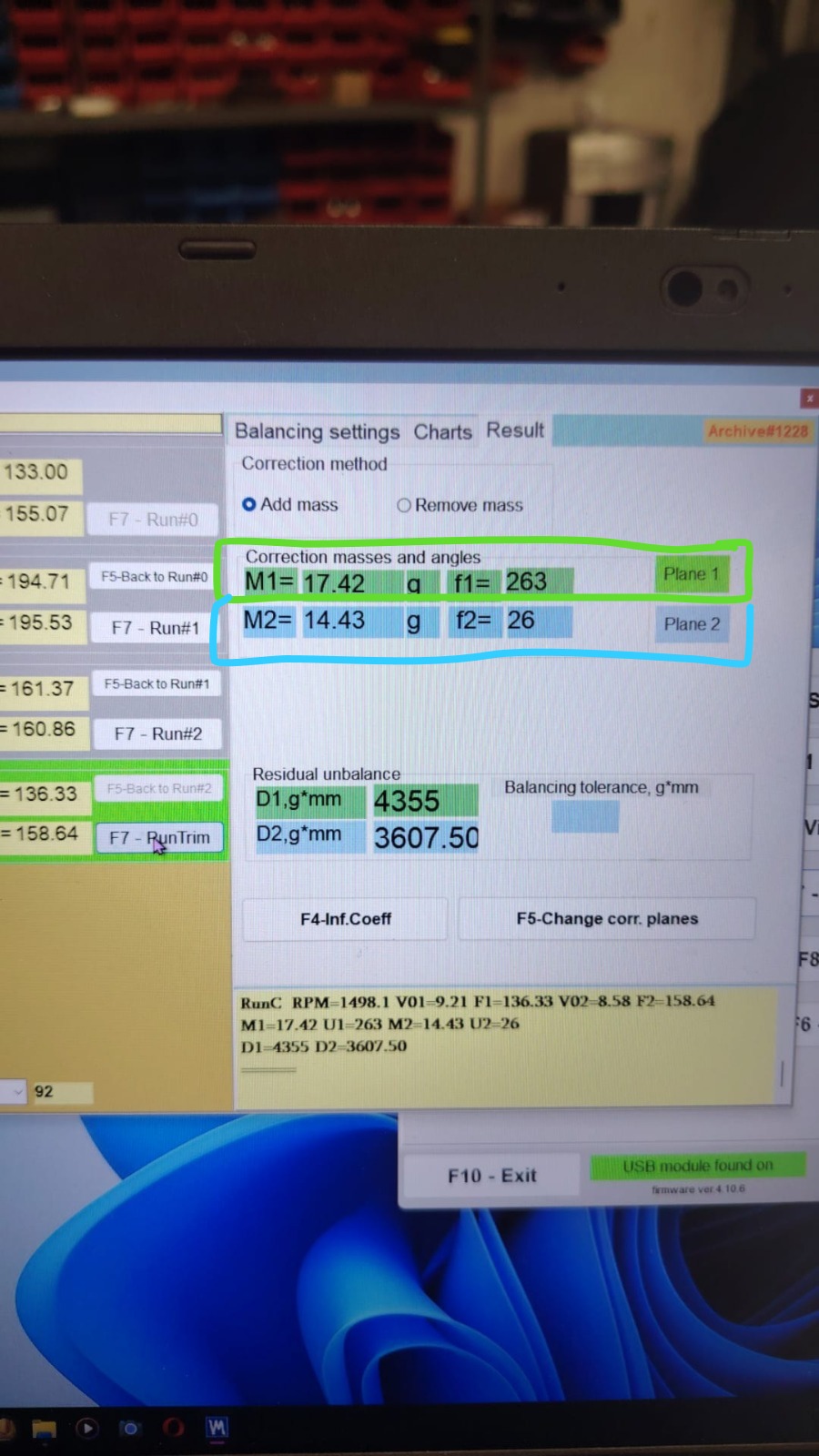
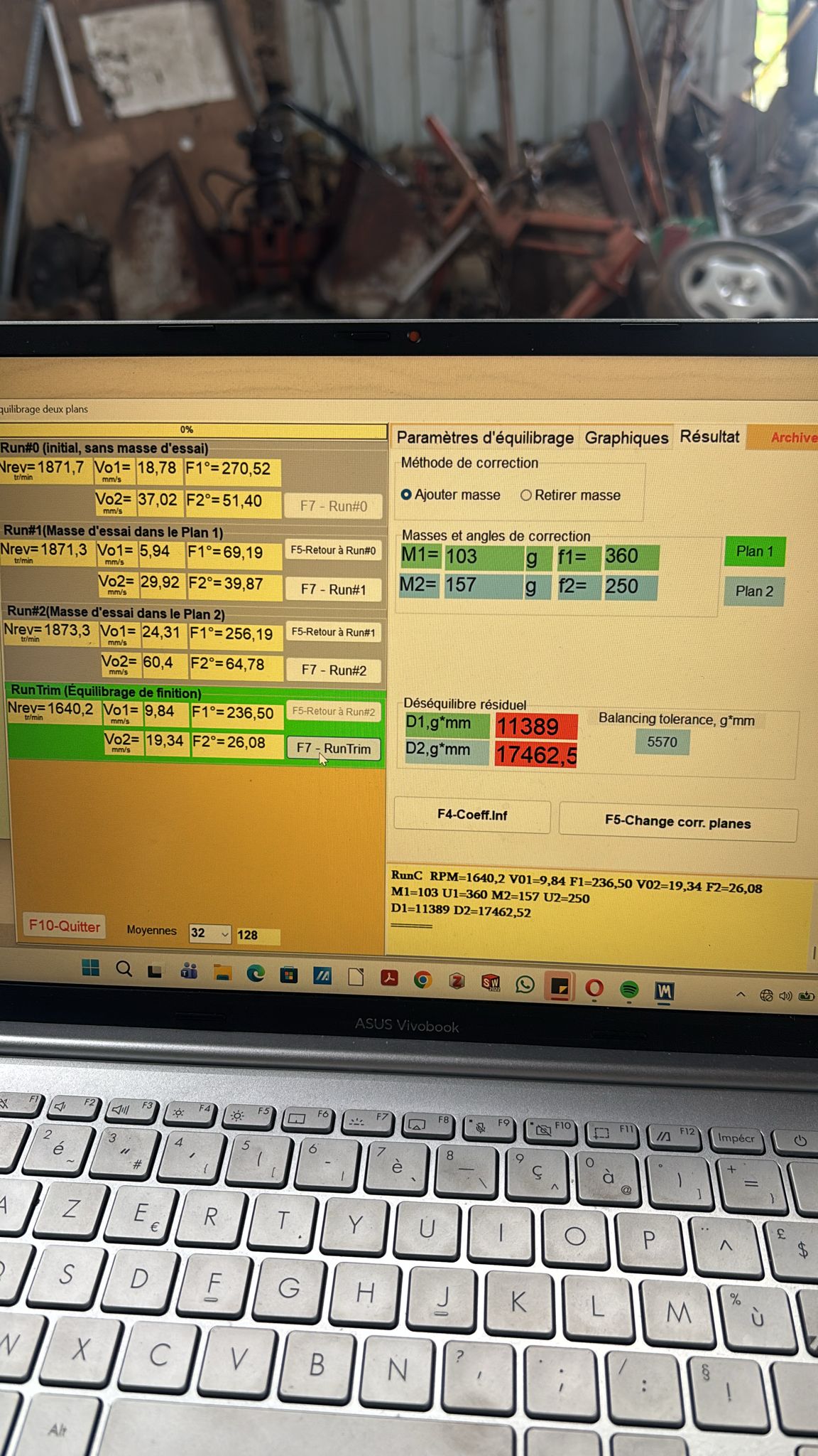
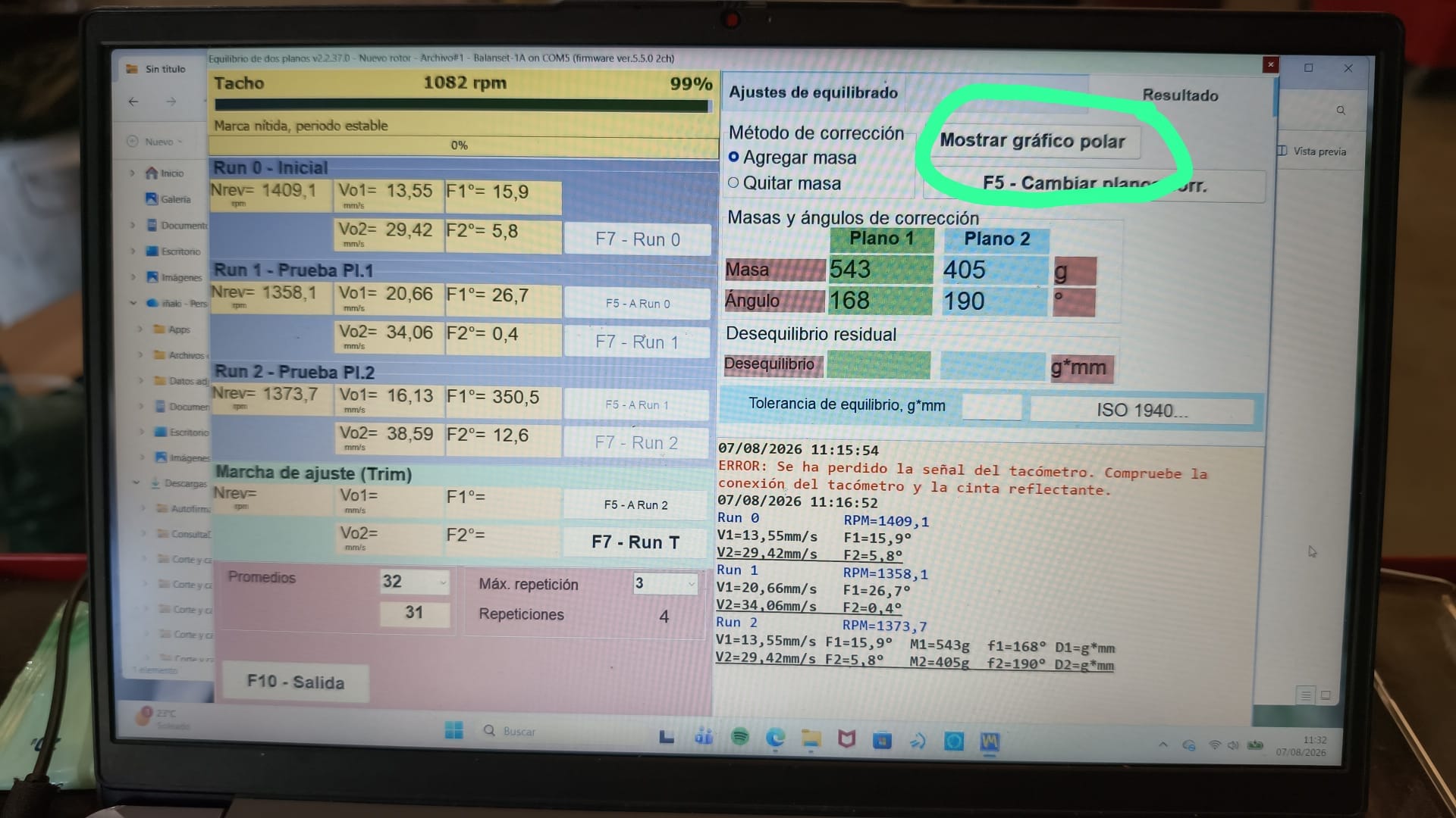
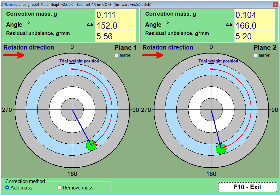
Käikude järjekord sõna-sõnalt toelt: “Run#0 — käivita rootor täiesti ilma raskuseta… Run#1 — paigalda katseraskus tasandisse 1… Run#2 — katseraskus on liigutatud tasandist 1 tasandisse 2 (mitte lisatud peale!). Pärast Run#2 eemalda kõik katseraskused ja paigalda ainult tarkvara arvutatud korrigeerivad massid.”
Kuidas nurka lugeda — kõige olulisem punkt
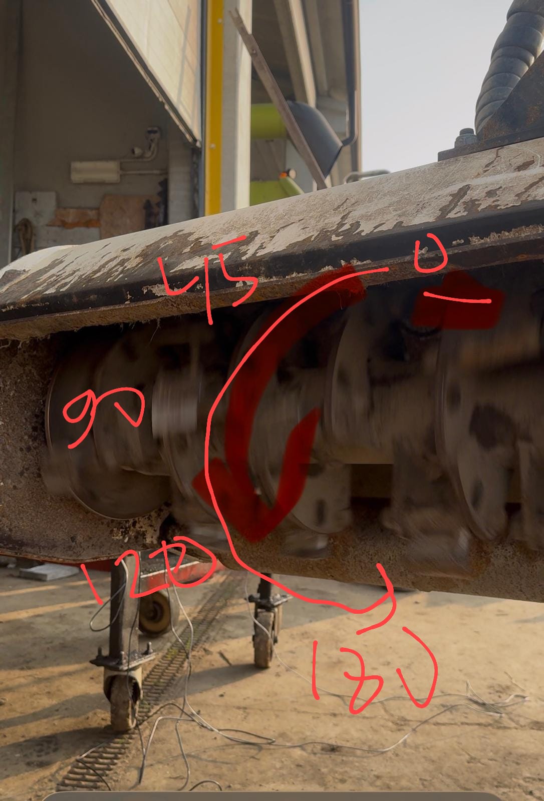
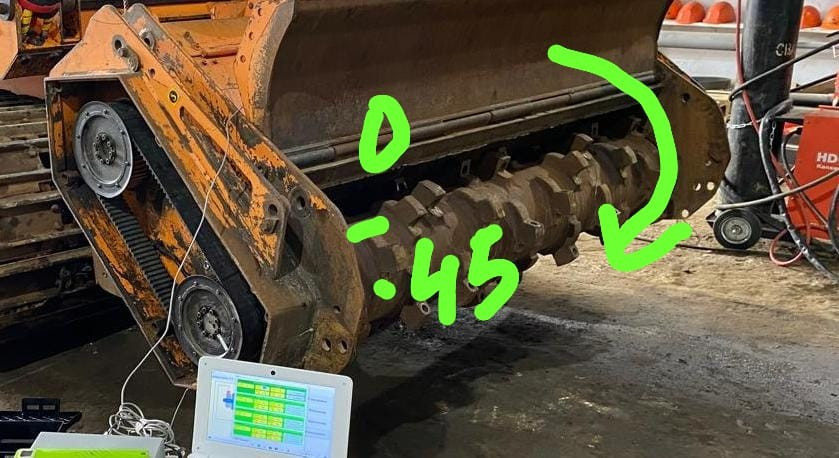
- Nurka loetakse prooviraskuse asukohast, rootori pöörlemise suunas.
- Näide: prooviraskus oli “kell 12” asendis, rootor pöörleb päripäeva (nagu te seda vaatate), arvutus ütleb 90° → korrektsiooniraskus läheb “kell 3” asendisse.
- Klassikaline viga on nurga lugemine pöörlemisele vastupidises suunas: raskus paigaldatakse 70° asemel asendisse 360−70=290° ja vibratsioon suureneb. Kui pärast raskuse paigaldamist halvenes tulemus täpselt peegelpildis, kontrolli nurga lugemise suunda.
- “Fikseeritud asenditega” (terad, poldid) annab programm asendinumbrid (nt Z5) ja jagab massi kahe lähima vahel.
Korrektsiooniraskuste paigaldamine
- Paigalda pool arvutatud massist (kolmandik kulunud masinatel). Süsteem on peaaegu alati mittelineaarne; täismass “ületab” sihtmärki sageli. Seade korjab jäägi järgmises iteratsioonis.
- Materjal — teraslehed/nelikantvarras (nt 20×20 mm), kaalutud kaaludel.
-
Kinnitamine: keevitamine on multšeritel ja ventilaatoritel tavaline (arvesta umbes 100 g keevisõmblusega); poldid/seibid neetidel sobivad õhukestele tiivikutele; voolikuklambrid sobivad kardaanvõllidele (kinnita keermeliimiga). Liimitavad raskused tulevad määrdunud või õlistelt pindadelt lahti. Proovi- ja korrektsiooniraskus paigaldatakse samale raadiusele.
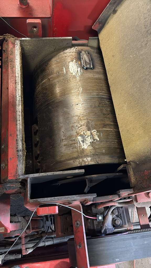
- Materjali eemaldamist (puurimist) kasutatakse siis, kui lisamine ei ole võimalik; programm oskab arvutada “eemaldamiseks” (märkeruut).
Kontrollkäik ja iteratsioonid
- RunC — kontrollmõõtmine paigaldatud raskustega.
-
Jälgi langust: normaalne dünaamika on mitmekordne 1–2 iteratsiooni kohta (nt 30 → 7 → 3 mm/s).
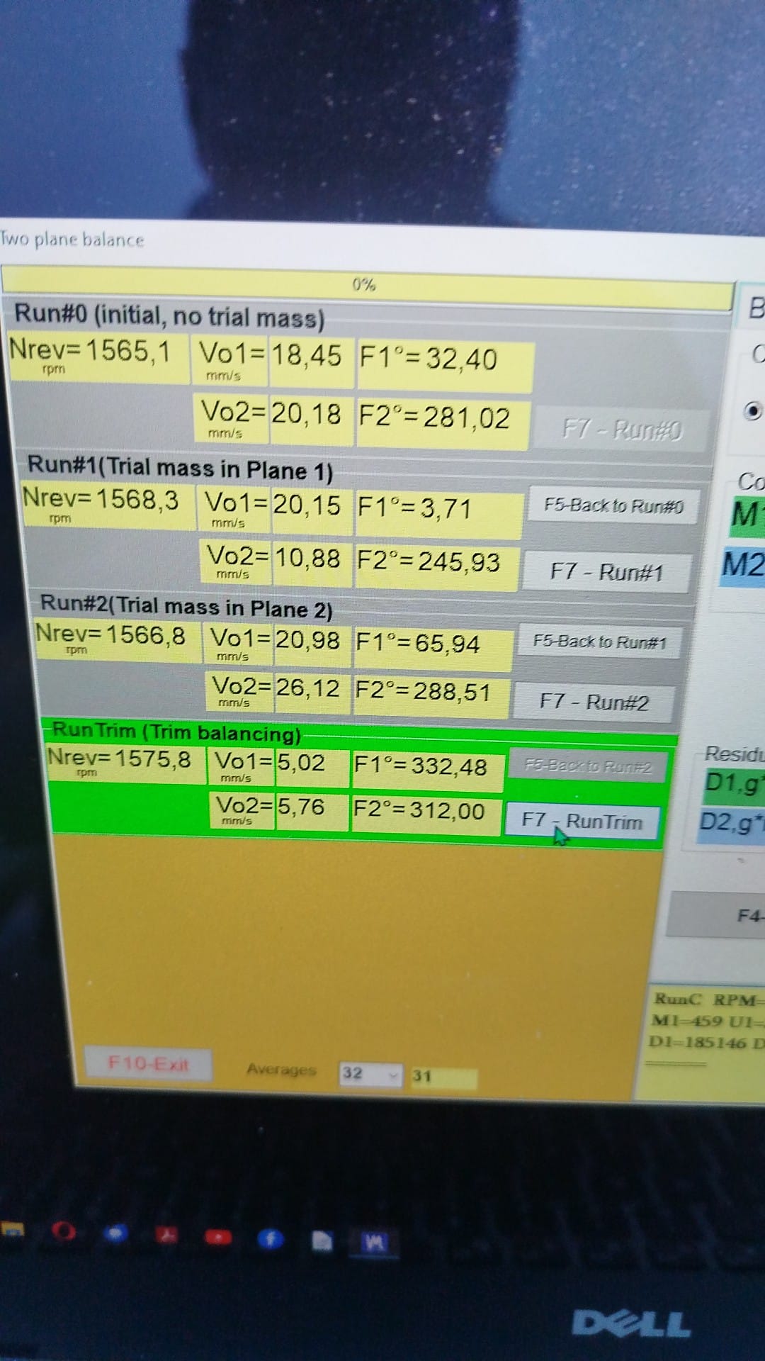
Täielik Run0 → Trim tsükkel reaalsel multšeril. 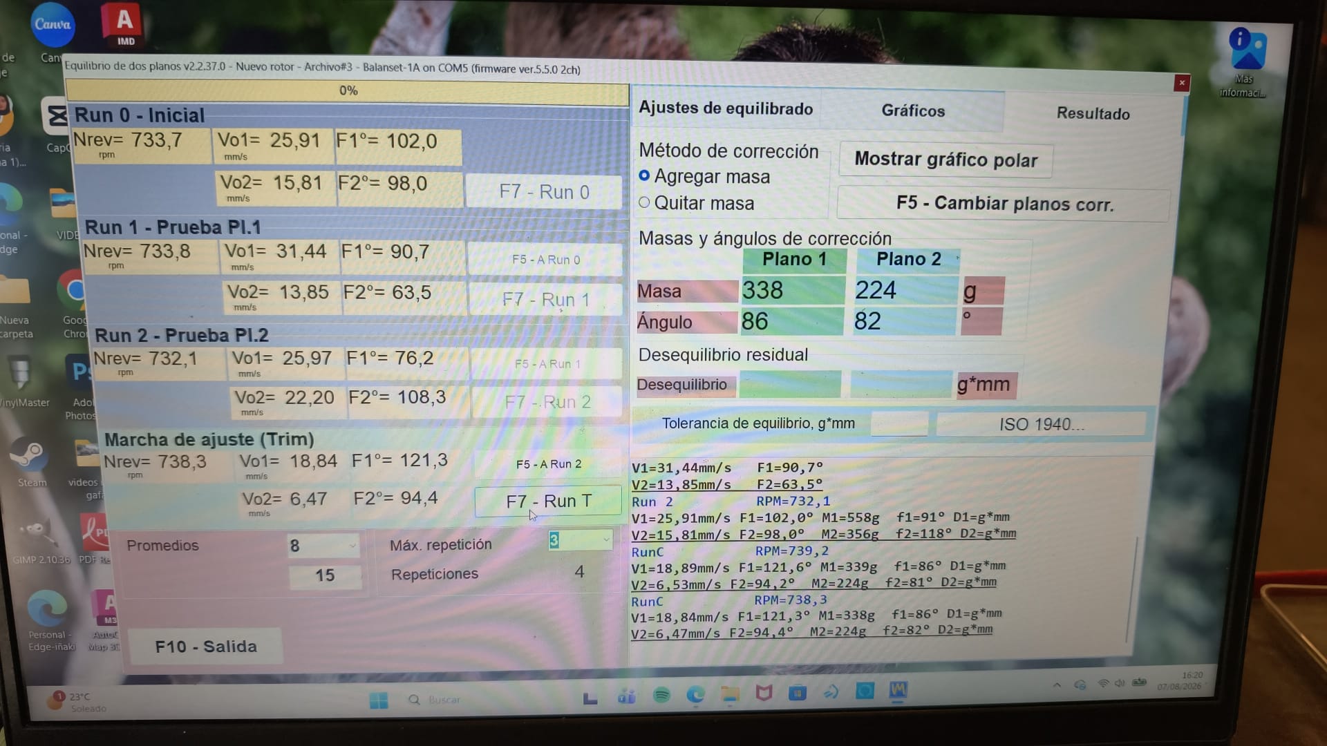
Edukas trimmimiskäik. - Programm arvutab lisaraskuse. Korrake, kuni jääte tolerantsi piiresse (peatükk 06).
- Kui alustasid vähendatud pöörete arvuga — tõsta töökiiruseni ja trimmi seal.
- Kui vibratsioon kasvas — peatuge, ärge keevitage rohkem peale. Minge peatükk 07.
Ühe tasapinna tasakaalustamine
Kõik sama, kuid kaks käiku: Run 0 ja Run 1 (katseraskus). Andur — X1 korrigeerimistasandile lähimal toel.
Tasakaalustamine teljel (metallilõikepingil)
Kui rootorit tasakaalustatakse masina teljel, kompenseeritakse telje ekstsentrilisus rootori pööramisega telje suhtes 180° (programmis märkeruut “Mandrel”). Takomeetri märk jääb teljele.
Väljade järjekorra spikker
1. Mehaanika korras? (lõtk, praod, kinnitused, noad)      → jah
2. Andurid radiaalselt, X1/X2 vahetamata                 → jah
3. Märk rummul, pöörete näit stabiilne                   → jah
4. Vibromeeter: amplituud/faas stabiilne                 → jah
5. Tasakaalustamine: raadius sisestatud, grammid, "lisa" → jah
6. Run0 → Run1 (katsekoormus pl.1) → Run2 (katsekoormus pl.2)
7. Katsekoormus muutis näitu ≥20-30%?                    → jah
8. Paigalda POOL arvutatud massist, nurk pöörlemise SUUNAS
   katseraskuse asukohast
9. Kontrollkäik → lisamine → korda
10. Tolerantsi piires? → koosta aruanne, eemalda katsemärgid, pakenda
Kui kaua see aega võtab
Õppestendil — minutid. Päris ventilaator või korras mehaanikaga niiduk — umbes 1,5 tundi kaasa arvatud anduri seadistamine ja raskuste keevitamine. Kui masin on rikkis, võib see võtta päevi (vaata juhtumianalüüse) — ja see ei ole seadme süü.

