Балансталау қызметтері › Бұрандалы конвейерлер мен ұлулар
Бұрандалы конвейер мен ұлуды балансировкалау — жұмыс жылдамдығында, орнында
Астық үрлегіштер, азықтық бұрандалар мен өнеркәсіптік бұрандалы конвейерлер — ұзын, жіңішке роторлар; олардың бетінің бір жері тозған немесе дәнекер массаның таралуын ауыстырған сәтте екі жазықтықтағы дисбаланс пайда болады. Біз оларды балансировкалаймыз орнында, жұмыс жылдамдығында — жабдықты сеңкіре демонтаждамай, жорамалсыз — материалдың тегіс және сенімді ағынын қалпына келтіре отырып, мойынтіректердің мезгілсіз істен шығуын тоқтатамыз.
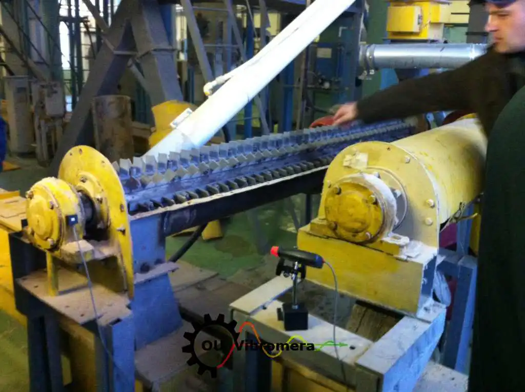
In short: Бұрандалы конвейер мен ұлуды балансировкалау жұмысы ықпал коэффициентінің екі жазықтықтағы әдісін қолданып, қалыпты жұмыс жылдамдығында орнында жүргізіледі. Екі ұшындағы мойынтірек корпустарына вибрация акселерометрлері орнатылады, лазерлі тахометр білік жылдамдығын өлшейді; Balanset-1A әрбір жазықтық үшін нақты түзету массасы мен бұрышын есептейді. Роторды шешпестен, науаны бөлшектеместен — әдеттегі жұмыс бір сағаттан аз уақытта аяқталады, вибрацияны 70 % және одан да көп азайтады, мойынтіректердің қызмет ету мерзімін сегіз және одан да көп есе ұзартады.
Бұрандалы конвейеріңіздің немесе ұлуыңыздың балансы бұзылғанының белгілері
Бұрандалы конвейерлер салыстырмалы түрде төмен жылдамдықта жұмыс істейді, алайда тіпті шағын масса эксцентриситеті білік бойынша толық ұзындыққа таралып, күтпеген деңгейдегі вибрация тудырады. Мына ескерту белгілеріне назар аударыңыз:
Аугерлер неліктен тепе-теңдігін жоғалтады — және бұл қандай шығынға әкеледі
Бұрандалы конвейер роторы ықшам желдеткіш немесе сорғы жетегінен түбегейлі ерекшеленеді: оның массасы ұзын, салыстырмалы түрде серпімді біліктің бойына таралған, бұл оны өздігінен екі жазықтықтағы дисбалансқа бейімді етеді, ал бір түзету салмағымен бұны жою мүмкін емес. Дисбаланс біртіндеп біркелкі емес абразивтік тозу салдарынан спираль қалақтарының, өнімнің жиналып қалуы спиральдің бір жағында, коррозиялық ойылу, сондай-ақ біліктің бойындағы масса бөлінісін өзгертетін жөндеу дәнекерлеулері немесе ауыстырылған қалақ бөліктері нәтижесінде артады. Астық үрлегіштерде және пневматикалық тасымалдау аугерлерінде спираль жеткілікті жоғары жылдамдықпен айналатындықтан, орталықтан тепкіш күш тіпті шамалы эксцентриситетті жүздеген ньютондық шайқалу күшіне дейін күшейте алады.
Операторлар нашарлаған тербелісті жиі құрылымдық мәселе деп қате санап, бекіту бұрандаларын қосу немесе қаттырақ жақтаулар орнату арқылы жауап береді — бұл симптомды жасырады, ал негізгі себеп подшипниктерді тоздырып, тығыздауыштарды зақымдап, дәнекерлеу жіктерін шаршата береді. Орталықтан тепкіш күш айналу жылдамдығының square квадратына пропорционал өскендіктен, 300 rpm-де орташа тербіліс тудыратын шамалы масса ауытқуы 600 rpm-де төрт есе нашарлайды. Бір орнында тексеру барысында екі жазықтықтағы дисбалансты түзету жүктемені көзінде жояды, және жабдық айлар емес, жылдар бойы тегіс жұмыс істейді.
Тербелісін екі есеге азайту неге подшипник өмірін ұлғайтады
Аугерді қалай теңестіреміз — қадамдық нұсқаулық
Balanset-1A ықпал коэффициенттері әдісін пайдаланады; бұл әдіс ұзын бұрандалы роторлардың екі жазықтықтағы нақты жағдайына бейімделген. Сол жүйелі процедураны өзіңіздің техникалық қызмет көрсету тобыңыз орындай алады:
- Датчиктерді орнатыңыз. Тербіліс акселерометрлері екі ұштық подшипник тұрғысына бекітіледі, ал лазерлік тахометр біліктегі шағылыстырғыш жолаққа бағытталады. Бөлшектеу қажет емес — бұранда жұмыс барысында қалыпты жылдамдықпен айналады.
- Бастапқы өлшеу жүргізіңіз. Толық жылдамдықтағы бір айналым жұмысы тербіліс амплитудасы мен фазалық бұрышты екі подшипник жазықтығында бір мезгілде жазады, осылайша ағымдағы екі жазықтықтағы дисбаланс жағдайы анықталады.
- Сынау салмағы қосыңыз. Белгілі сынақ массасы біліктегі немесе қалақтағы бір ұшына жақын дәл өлшенген бұрыштық орынға қысқышпен бекітіледі. Ротор қайтадан жұмыс істейді, осылайша құрылғы екі жазықтықтың белгілі ауытқуға қалай жауап беретінін тіркейді — ықпал коэффициенті.
- Құрылғыға есептеуді орындат. Balanset-1A екі жазықтықтың ықпал коэффициенттері матрицасын шешеді және әрбір түзету жазықтығы үшін дәл түзету массасы мен сағаттық бұрышты шығарады. Қажет болса, қарама-қарсы ұштағы екінші сынақ салмағы шешімді нақтылайды.
- Түзету салмақтарын орнатыңыз. Түзету массалары есептелген бұрыштық орналасуды ескере отырып, бұрандалы ротордың екі ұшындағы есептелген орындарда дәнекерленеді, бұрандаланады немесе қысқышпен бекітіледі.
- Тексеру және құжаттандыру. Соңғы өлшеу жұмысы қалдық дисбалансының қолдану үшін талап етілетін ISO 21940-11 сыныбына сәйкестігін растайды. Balanset-1A әр жазықтықтағы алдыңғы және кейінгі көрсеткіштерді көрсететін басылған есепті жасайды.
Бізің не балансталайтын
- Астық элеваторлары мен астық үрлегіштерінің шнектері
- Жем диірмендері мен жем тасымалдағыштарының бұрандалары
- Сыпыр материалдарды өңдеудегі көлденең бұранда конвейерлері
- Еңкіш және тік бұранда көтергіштері
- Цемент және заттас бұранда беруіштері
- Экструдер беруіш бұрандалары (алынатын ротор)
- Ауылшаруашылық комбайндарының түсіру шнектері
- Шаң жинағыш және күл тасымалдағыш бұрандалар
- Пневматикалық тасымалдау шнектері және астық үрлегіштері
- Кез келген ұзындықтағы арнайы спираль конвейер роторлары
Төлеу өлшемдері және стандарттар
ISO 21940-11 (бұрын ISO 1940-1) қатты роторлардың балансировка сапа сыныптарын реттейді. Ұзын білікті бұранда роторлары әдетте сапа сыныбына жатады G 6.3 (жалпы өнеркәсіптік машиналар) немесе G 2.5 жұмсақ жұмыс талап етілетін жерлерде — мысалы, жоғары жылдамдықты астық үрлегіштерінде немесе дәл мөлшерлеу жабдықтарына жеткізетін конвейерлерде. Стандарт рұқсат етілген қалдық меншікті дисбаланс e мәнін анықтайдыper ротордың жұмыс жылдамдығының функциясы ретінде, нақты және өлшенетін қабылдау критерийін береді.
Материалды пневматикалық тәсілмен тасымалдайтын жоғары жылдамдықты астық үрлегіштері үшін желдеткішті балансировкалаудың ISO 14694 немесе машина жасаушының өз техникалық талаптары да қолданылуы мүмкін. Біз сіздің қолданбаңыз талап ететін сапа сыныбына дейін балансировкалаймыз және әр балансировка жазықтығы бойынша г·мм-мен берілген қалдық дисбаланс нәтижесін — қол жеткізілген сыныппен бірге — құжатталған түрде ұсынамыз. Жұмысты бастамас бұрын ротордың рұқсат етілген төзімділігін табу үшін қалдық-дисбалансы калькулятор пайдаланыңыз.
Balanset-1A — сіздің толық өндіктік-балансталау құраны
Бұл бетте барлық операциялар бір портативті құралмен орындалады: Балансет-1А. Бұл екі арналы динамикалық балансировшы және вибрация анализаторы, ол бұранда конвейері мен шнек роторларын балансировкалайды олардың өзінің тіліндіктеріндеде, жұмыс жылдамдығында, үш жүгірістегі әсер коэффициенттері әдісін қолдана отырып — бағдарламалық жасақтама әр жазықтық үшін дәл түзету массасы мен бұрышын есептеп, есепті сақтайды.
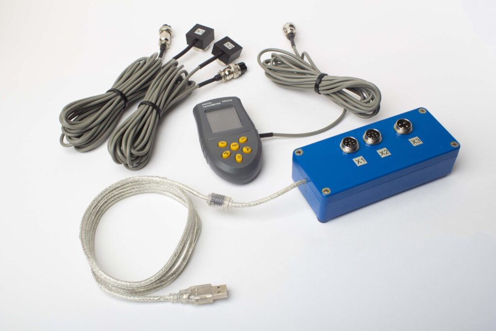
Толық Жиынтықта не бар
€1,975 · Толық комплект, қоймада, ҚДҚ бланкісі
- Өлшеу блогы (USB, 2 канал)
- Екі вибрация акселерометры (4 м кабель, 10 м сөзсіз)
- Лазер тахометр / оптикалық фаза сенсоры (50–500 мм)
- Сенсор үшін магниттік тұрғын
- Сынама және түзету ағырлықтары үшін цифрлық масштаб
- Windows балансировка және талдау бағдарламасы
- Пластикалық тасымалау ыдысы
Full Kit
Блок · 2 сенсор · лазер тахометр · магниттік тұрғын · цифрлық масштаб · бағдарлама · тасымалау ыдысы. Қораптан балансировка бастау үшін қажетті барлығы.
OEM set
Блок · 2 сенсор · лазер тахометр · бағдарлама. Ішінара адам ынамдықтау интеграторлары үшін, тұрғын, масштаб және ыдыс бар, немесе балансировка машинасында блокты енгізетіндер.
| Parameter | Value |
|---|---|
| Өлшеу каналдары | 2 (бір- және екі-жазықтық балансировка) |
| Вибрация қарқындылығының диапазоны | 0.2–80 mm/s RMS |
| Жиілік диапазоны | 5–1000 Hz (≤10% amplitude error above 550 Hz) |
| Өлшеу дәлігі | ±5% толық шкаласынан |
| Method | 3-қоса әсер коэффициенті (1 немесе 2 тегістеу жазықтығы) |
| Analysis | 振幅 & фаза 1×-те, FFT спектрі & толқын түрі, сақталған есептер |
| Laptop | Қоса алынмаған (Windows ПК, сауда бойынша қол жетімді) |
Орнында балансировкалау мен балансировка машинасы — бұранда роторыңыз үшін қайсысы дұрыс?
| Factor | Орындық тегістеу (Balanset-1A) | Тегістеу машинасы (майстерлік) |
|---|---|---|
| Ротор конвейерден алынды ма? | Жоқ — орындықта жүреді | Иә — толық ыдырау қажет |
| Науа немесе қаптама ажыратылды ма? | No | Yes |
| Өндіріс тоқтаулары | Сенсорды орнату ғана (<15 мин) | Бірнеше сағаттан бірнеше күнге дейін (бөлшектеп алу, тасымалдау, балансировкалау, орнына қайта орнату) |
| Тегістеу жылдамдығы | Нақты жұмыс жылдамдығы & жүктеме жағдайлары | Жеке төмен жылдамдықты бұрандалау |
| Біліктің иілуі & серпімділігін есепке алады | Иә — толық жинақ орнында теңгерімделеді | Ротор оқшауланған күйде, нақты бекіту жоқ |
| Екі жазықтықта түзету | Иә — екі ұштағы тіректер бір баруда | Yes |
| Standards met | ISO 21940-11 (G 6.3 / G 2.5) | ISO 21940-11 |
| Equipment cost | €1,975 (Толық Құрал) | €10,000 – €50,000+ |
| Типтік жұмыс уақыты | <1 сағат объектіде | Барлығы 1–3 күн |
Бұранда ротоны жұмыс жылдамдығында айналдыруға болатын және қаттылық критерийі орындалатын жағдайларда орнында теңгеру — артықшылықты тәсіл болып табылады. Шеберхана машинасы жұмыс уақыты нөлге тең жаңа роторлар үшін не басқа жөндеу жұмыстары үшін толық бөлшектеуді қажет ететін өте ірі немесе зақымдалған роторлар үшін ұтымды.
Бұрандалы роторды нақты теңгеру жағдайлары
Бұранда & бұранда конвейеріне арналған тегін есептегіштер
Бұранда & бұранда конвейерін теңгеру бойынша жиі қойылатын сұрақтар
Бұранда конвейерін екі жазықтықта теңгеру шынымен қажет пе?
Теңгеру кезінде бұранданы науада қалдыруға бола ма?
Бұранда конвейерлеріне қандай теңгеру сапа дәрежесі қолданылады?
Тозған ұшқыштарды ауыстырғаннан кейін де бұрғымыз қатты дірілдейді — неліктен?
Түзету салмағы әдетте қанша болады?
Мұны Balanset-1A көмегімен өзіміз жасай аламыз ба?
Теорияны білік түйінінде
Бұрғыңызды немесе бұрандалы конвейеріңізді теңгеріңіз — орнында, бүгін
Balanset-1A ұзын бұрандалы роторлар үшін қажетті екі жазықтықтағы толық түзетуді орындайды; жұмыс жылдамдығында, әр түзету жазықтығындағы нақты қалдық дисбалансты көрсететін құжатталған нәтижемен жұмысты аяқтайды — ISO 21940-11 G 6.3 немесе G 2.5 деңгейіне сай, қандай қолданба талап етсе соған сәйкес. Бөлшектеу жоқ, өндіріс тоқтауы жоқ.
