← База знања Balanset-1A — сва поглавља
Кључна чињеница из година подршке: у приближно 90% случајева неуспелог балансирања узрок је механички квар машине или резонанца, а не уређај и не неуравнотеженост. Уређај мери поштено, али балансирање не може да излечи зазор, пукотину или резонанцу.
Дијагностичко стабло
Пролазите кроз кораке одозго надоле.
Корак 1. Да ли су очитавања уопште стабилна?
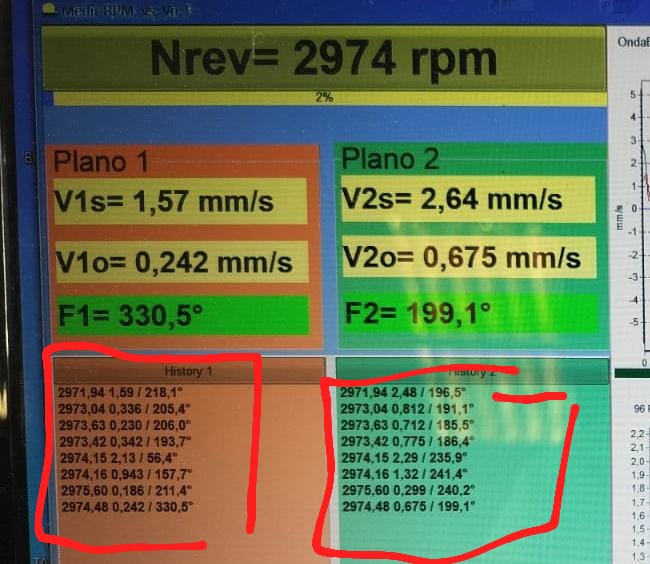
Извршите 2–3 мерења заредом на истим обртајима, не мењајући ништа. Амплитуда мора да се понавља у оквиру ~10–20%, фаза у оквиру ~10–20°.
Очитавања варирају → рано је за балансирање. Узроци нестабилности:
- Зазор лежаја — залуљати ротор полугом, каишеви скинути.
- Лабава конструкција: пукотине, непритегнути вијци, померање носача, слободно висећи поклопци или рамови.
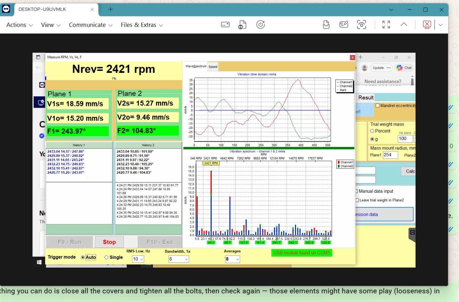
- Резонанција — промените RPM за 50–100: ако се вибрација мења неколико пута, налазите се на резонанци или близу ње.
- Наслаге материјала на ротору или материјал који отпада, померање слободно окачених ножева.
- Проблем тахометра — двоструко окидање, одсјај (види поглавље 08): фаза скаче услед лажних ознака.
Корак 2. Погледајте спектар (FFT) — ко се тресе?
| Слика спектра | Вероватан узрок | Шта урадити |
|---|---|---|
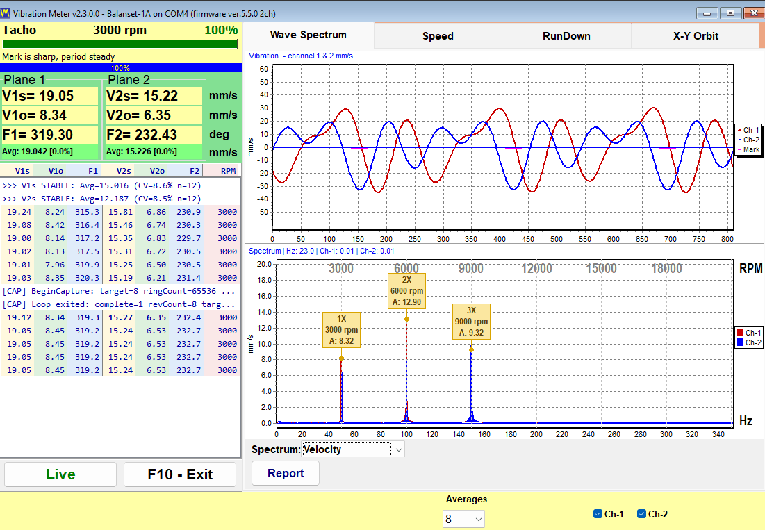
| 1x доминира | Неравнотежа | Балансирајте — на добром сте путу |
| 2x изнад 1x | Неусклађеност вратила (60–70%), лабавост (20–30%) | Проверите спојнице/поравнање, елементе за причвршћивање. Балансирати тек после отклањања |
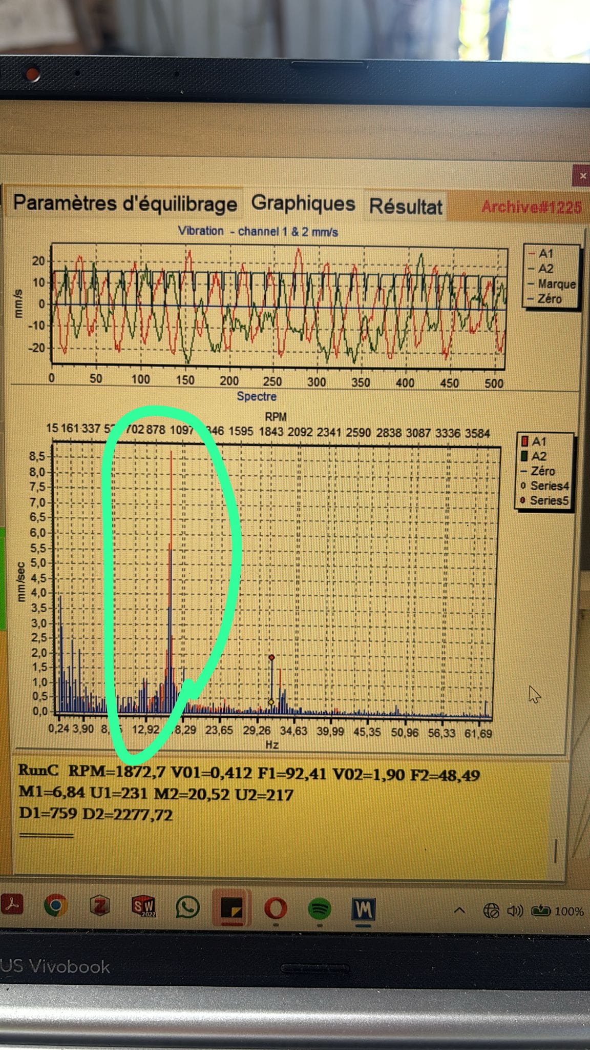
| Мноштво хармоника 3x, 5x, 6x | Механичка лабавост: завртњи, налегања, зазор ослонца, пукотина | Генерални ремонт машине |
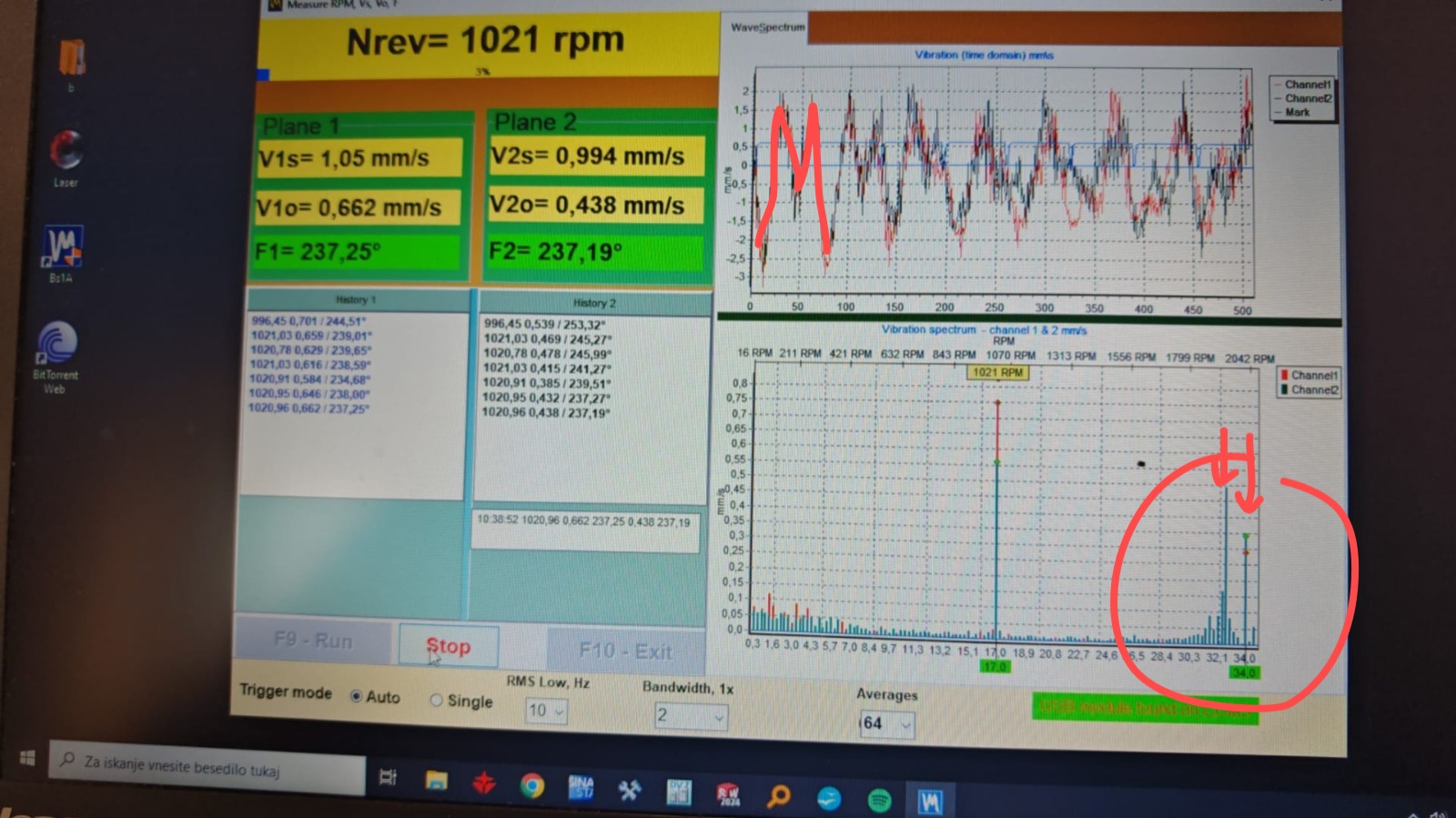
| Велики врх удаљен од фреквенције ротације | Други извор: суседно вратило, каишни погон, редуктор | Пронађите шта се окреће на тој фреквенцији |
| Врх на умношку мреже (300 Hz = 6×50) | Електромагнетне сметње од VFD-а | Угасите фреквентни претварач током успоравања: врх нестане → електрично је. Уземљење, феритни прстенови, филтери |
| Врх остаје на месту када се RPM мења | Конструктивна резонанца или спољашњи извор | RunDown, промените RPM балансирања |
| Високофреквентни „тепих“ | Лежајеви | Замените лежајеве |
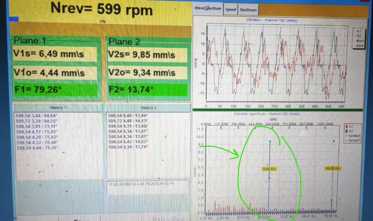
| Нискофреквентни врх на неколико Hz, не 1x | Аеродинамика/темељ | Пример: вентилатор доминантно на ~10 Hz — аеродинамика канала, а не неуравнотеж |
Корак 3. Знаци резонанце
- После постављања израчунатог тега, вибрација порасла;
- уређај у свакој итерацији тражи све већу масу;
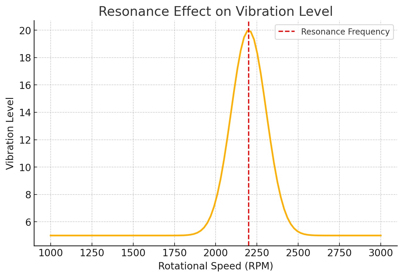
- мала промена обртаја → велика промена вибрације;
- фаза нагло осцилује када се RPM мења.
Решење:
-
Снимите график RunDown (слободног успоравања): убрзајте ротор, па искључите погон. Уређај бележи амплитуду и фазу у зависности од броја обртаја. Врхови означавају зоне резонанце; у таквој зони фазна крива има оштар прелом.
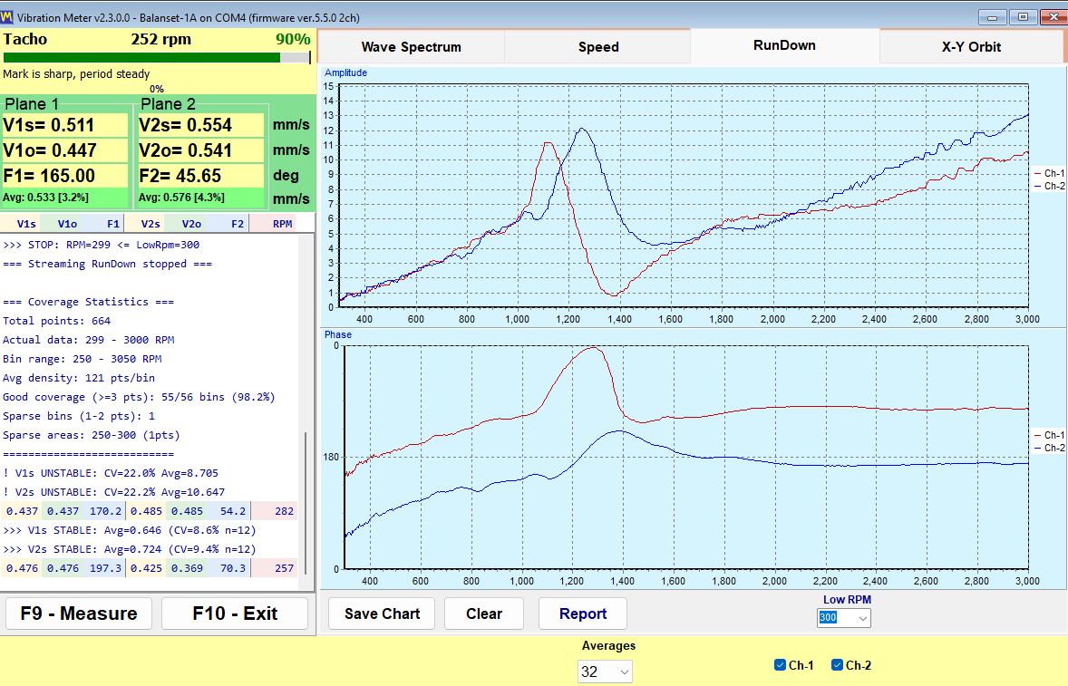
Екран RunDown: горњи график — амплитуда, доњи — фаза. Врх на ~1100–1300 rpm са наглом променом фазе је зона резонанце; балансирати ван ње. 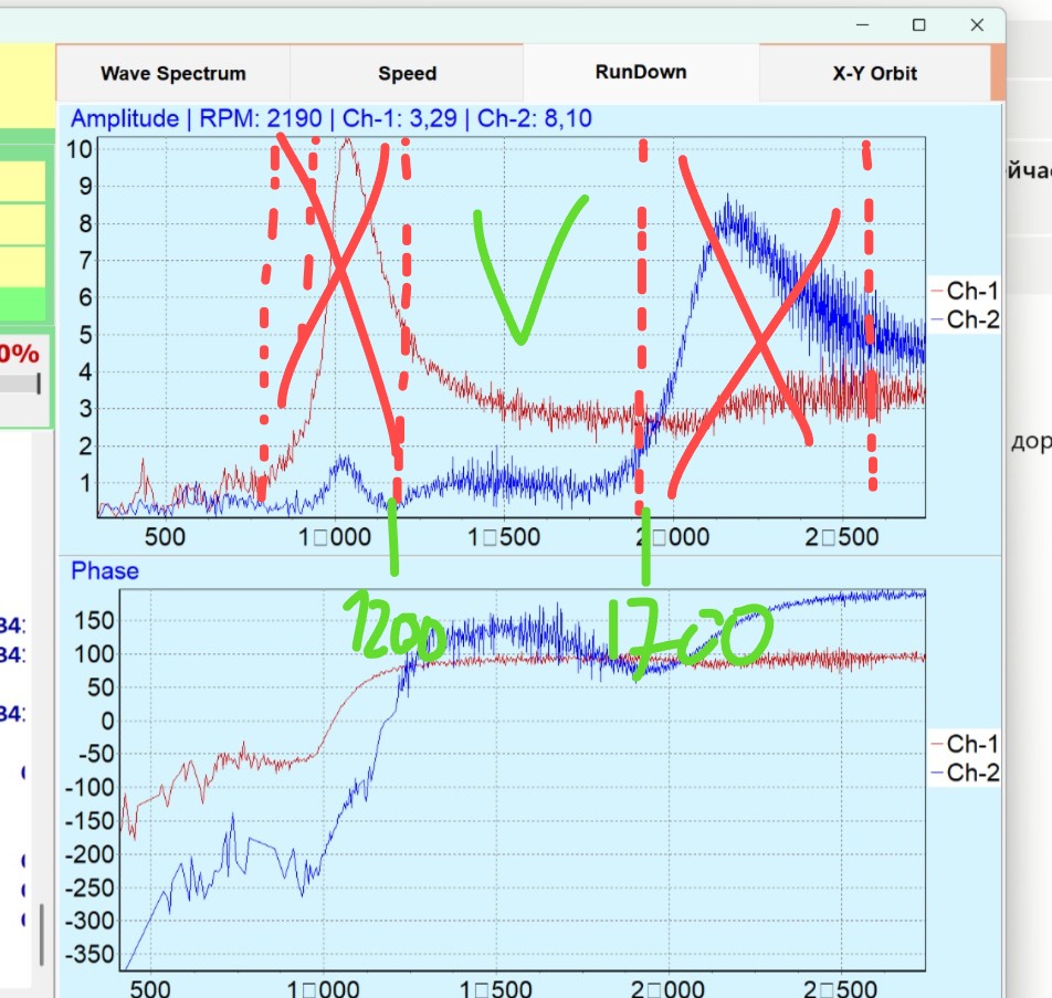
Без RunDown-а тражите резонанце помоћу виброметра: полазећи од ниског RPM, повећавајте га у корацима од 50–100 rpm и пратите вибрацију — нагли скок у неком кораку открива зону резонанце. Стваран пример: од 650 до 750 rpm вибрација је порасла пет пута → резонанца близу 755. Други: 70 mm/s при 1300 rpm, али 50 при 1400 → резонанца близу 1300; балансирајте на 800.
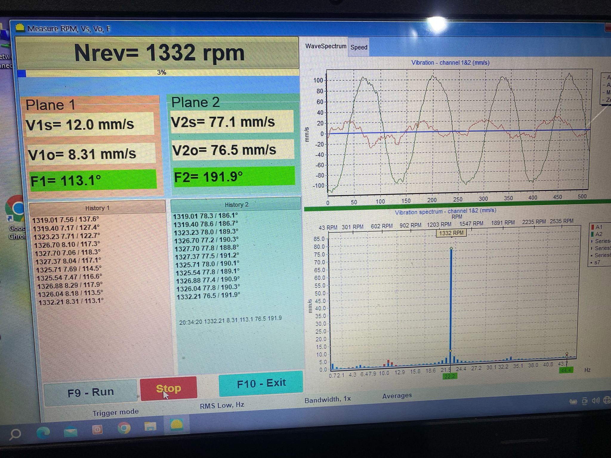
Рад близу резонанце: 77 mm/s. - Изаберите брзину балансирања изван зона резонанце, обично знатно испод њих (600–900 обр/мин за малчере). Пример: резонанце при ~420 и ~644 обр/мин, балансирање при ~844 обр/мин. У другом случају није успело при 1600, али јесте при 1000 обр/мин.
- После балансирања на обртајима ван резонанце подигните брзину на радне обртаје и извршите фину корекцију.
- Радикалније решење је промена крутости конструкције: ојачајте рам, подуприте га или промените ослонце. Машина која стоји директно металом на бетону често се понаша лоше; помажу антивибрациони ослонци или опруге.
Корак 4. Нелинеарност — поставим тег, али одзив није очекиван
Знаци: одзив на тег је непропорционалан; при уклањању тега вибрација се не враћа на почетну вредност (нешто у машини се помера/виси).
- У свакој итерацији поставите половину или трећину израчунате масе.
- Проверите да ли је пробни тег превелик: промена коју изазива треба да буде 20–30%, али не више од ~100%. Претежак пробни тег нарушава линеарни модел и води до прекорекције.
- Ако су почетне вибрације веома ниске (<1 mm/s), чак и 100–200 g може да изазове нагли скок. Смањите масу пробног тега.
- Ако се вибрације после уклањања тегова не врате на почетну вредност, потражите механички квар: нешто се помера у налегању, клину или пукотини.
Корак 5. Проверите сопствене грешке
Прођите кроз поглавље 09. Најчешће:
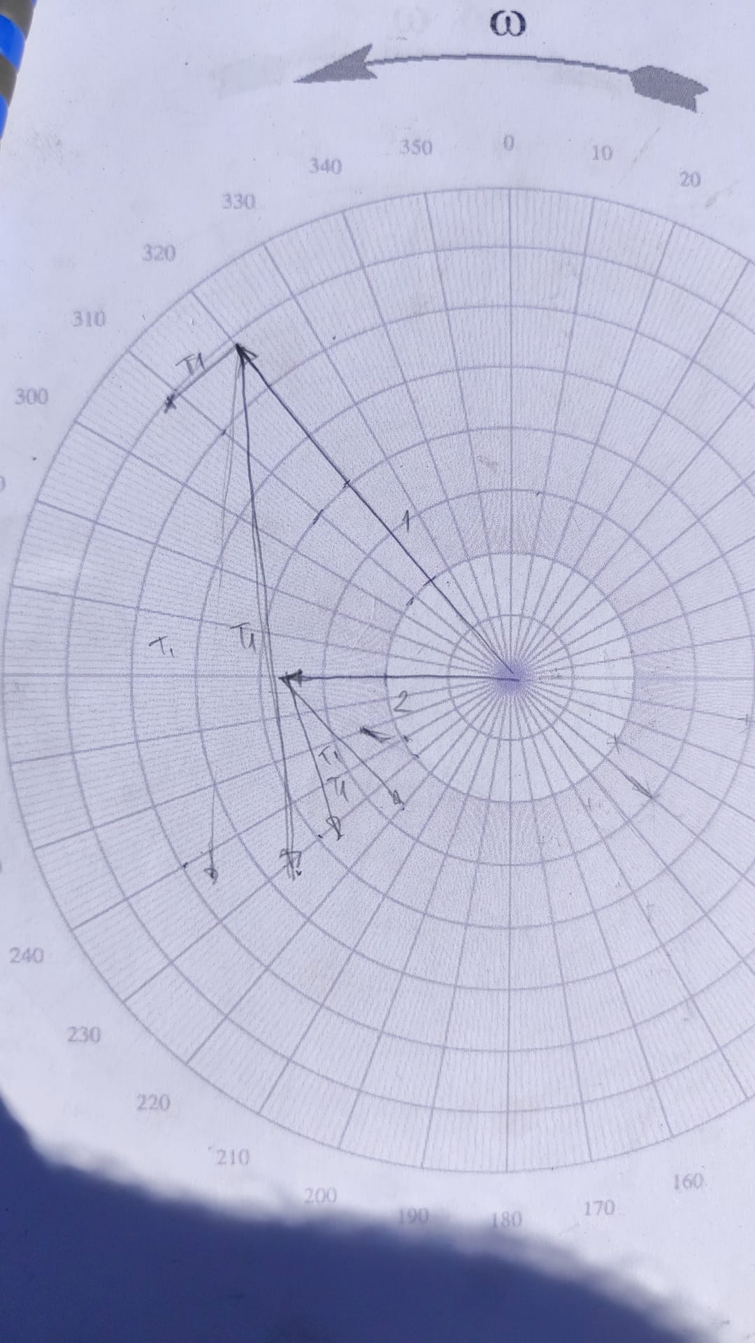
- угао је одмерен супротно смеру обртања (знак: вибрације су се приближно удвостручиле уместо да опадну);
- проценти уместо грама (радијус није унет);
- означено је поље „remove mass“ (уклањање масе) док заварујете тегове;
- ознака тахометра се померила између мерења;
- сензори монтирани аксијално или замењени X1/X2;
- RPM промењен усред серије;
- пробни тег није уклоњен када је програм претпоставио да јесте;
- балансирање без ножева/чекића који су уграђени накнадно.
Корак 6. Дефекти пронађени у стварним случајевима
Стварни узроци из праксе када балансирање није успевало:
- уништена спојница (двоструки диск) — сломљени делови унутра, невидљиви споља; нестабилна вибрација;
- криво вратило — 4–20 mm бацања; балансирање компензује само делимично, резултат је гори него обично (11 mm/s уместо 3);
- зазор у задњем лежају мотора — врх на ~85 Hz; чекало се на нови мотор;
- пукотина у ременици;
- поломљени носачи или ослонци малчера, који су после поправке поново напукли;
- истрошено лежиште — излечено наваривањем и поновном обрадом рукавца;
- тахометар је бројао 2 отвора на ременици као 2 ознаке, па се приказани број обртаја „удвостручио“, а прорачун је изгубио смисао;
- аеродинамика — усисавање канала уз недовољну крутост: нема шта да се балансира; очистити филтере и укрутити конструкцију.
- фреквентни претварач — врх од 300 Hz (6×50) нестаје када се фреквентни претварач искључи.
Корак 7. Када стати
Неке машине не могу да се избалансирају на лицу места док се не поправе. Чак је и искусна подршка током више од 10 година морала да одбије неколико послова: сечку комбајна, резач жбуња од 2,5 m и малчер на багеру. Ако је механика неисправна, реците клијенту да прво треба поправити лежајеве, вратило или рам, а затим балансирати. То је стручан закључак, а не пораз.
Кратак подсетник: зашто су вибрације порасле после постављања тега?
- Погрешан смер рачунања угла → проверите да ли сте рачунали у смеру ротације.
- Поље „remove mass“ (уклањање масе), означено током заваривања тегова, обрће резултат.
- Резонанца → RunDown, другачији обртаји.
- Превелик корак (пуна маса на нелинеарној машини) → половина масе.
- Механика (зазор/пукотина) → генерални ремонт.
- Лажне ознаке тахометра → фаза је погрешна, види поглавље 08.

