


About the experience of balancing the cardan shaft directly on the motor grader
Found an old correspondence between our lead specialist and one of our customers.
Correspondence from ten years ago!
Autor : Valery Davydovich
Introduction
I must admit that I was very surprised and pleased with the results of the letter written to us by Andrey Kobyakov, the driver of the motor grader.
His letter even surprised me – a specialist with more than 35 years of experience in the field of vibrodiagnostics and balancing. And for a long time I worked in the defense industry and balanced more than 1500 different machines and mechanisms starting from ordinary fans and smoke pumps and finishing with antenna guidance systems and unique gyroscopes.
And here for the first time in the field balancing of a powerful road machine – a motor grader!!!, the driver of which Andrey works.

Balancing cardan shaft, crankshaft and clutch basket directly on the motor grader
Andrey acquired our balancing instrument “Balanset-1” quite recently – at the end of August this year (2012).
In a little over two months since then, he has managed not only to master the hardware and technology of balancing, but to eliminate without disassembly imbalance of the main units of his machine (driveshaft, crankshaft with clutch basket, wheels).
Here’s how Andrew describes the work he did in his correspondence with us.
(With his permission I publish his letters without cuts and editing).
1. Letter from A. Kobyakov dated October 18, 2012
Hello, Valery Davydovich! I wanted to write to you. I mastered the work with the device rather quickly and everything is available for unprepared people like me. My notebook accepts the program without correction. My first time installing it on stationary computer, balancing the wheels, the result is better than at the tire fitting. Tried 2 driveshafts on the spot, balancing seems fine. In general, the device met my expectations for good functionality at a reasonable price. The other day I balanced the flywheel on the motor grader I work on myself. The initial imbalance was more than 8000 g*mm, the remaining imbalance was about 900 g*mm, with a tolerance of 400 g*mm. Could have done better, but left intentionally, because you will need to balance the clutch assembly. Then we will have to balance the engine-gearbox cardan on the same grader. It’s an eternal problem with motor graders. My superiors were kind of sarcastic about the job, but I guess time will tell.
In the process, a question arose: how do you stack corrective weights into one balancing weight? When balancing the gimbal it is more convenient. In my opinion in general it would be great if the program could make such calculation.
2. Letter from A. Kobyakov dated October 31, 2012
Hello Valery Davydovich!
I want to tell you about the work done. As I told you, I tried balancing the clutch assembly. The first attempt was unsuccessful. Initial imbalance was over 28,000 g*mm. Made the conclusion- misalignment. After that the assembly was disassembled and inspected. Detected worn alignment holes in the clutch housing and abrasion of the adjacent housing flats. Intermediate disk normal, drives new, but of questionable quality (lining displaced). I chose the new one myself, only one of the four was balanced. That’s the case. Assembly was more carefully with the help of the device. My colleagues were giving me the finger with my temple. I made an interesting discovery: the intermediate disc is set only in one position out of three and the basket too. As a result I balanced it to 2600 g*mm. The mass of the whole assembly flywheel + intermediate drive + basket is about 80 Kilo, radius 430mm, speed 1900-2000 rpm. The engine is happy, it runs smoothly.
Further the cardan. The first attempt was failed again, it has weight 15 kilos, length 650mm.
I checked flanges, crosses, everything is OK, but it doesn’t go. I took off the cardan. I turned it for half an hour. All the same, I spotted a slight radial movement in one of the crosses. Change of spider, balancing.
Result: initial unbalance at the first plane 1600 g*mm, at the second plane 1000 g*mm. Residual unbalance at 1 plane 36 g*mm, at 2 plane 9 g*mm. Applause. Curtain. The bosses are shocked.
Valery Davidovich, how can you evaluate such a job as a specialist?
3. Letter from A. Kobyakov dated November 7, 2012
Valery Davydovich, hello! I’m finally sending you the results of my work. On the photo is the first “happy” of our city. No one had ever done balancing before even on cars, let alone heavy machinery. The only exception is my experiments, more or less successful.
In the photo we see a rather massive driveshaft, on it are fixed with band clamps segments of lead rod
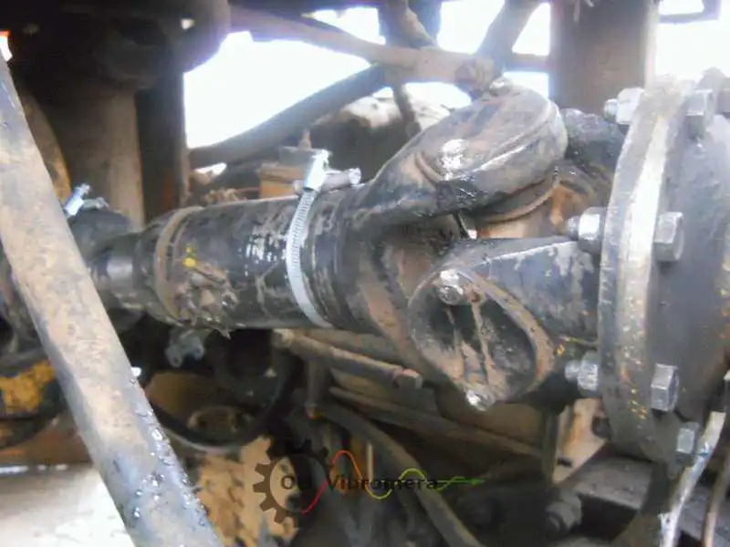
Fig.1 Photo of the cardan with corrective weights installed in planes 1 and 2.
You can also see the factory weight welded on. On the video you can observe a smooth rotation of the shaft. There is no movement of the gearbox (on the left in the video). No displacement of the engine (on the right) is observed. There is a significant reduction of noise in the cabin, the vibration is practically not felt. Minutes of balancing 29/10/2012 before repair of driveshaft (replacement of one cross member). Minutes of 31/10/2012 after repair. Protocols confirmed by our mechanic, who incidentally looked very negatively on this work.
(Note: Unfortunately, I could not find the video itself.)
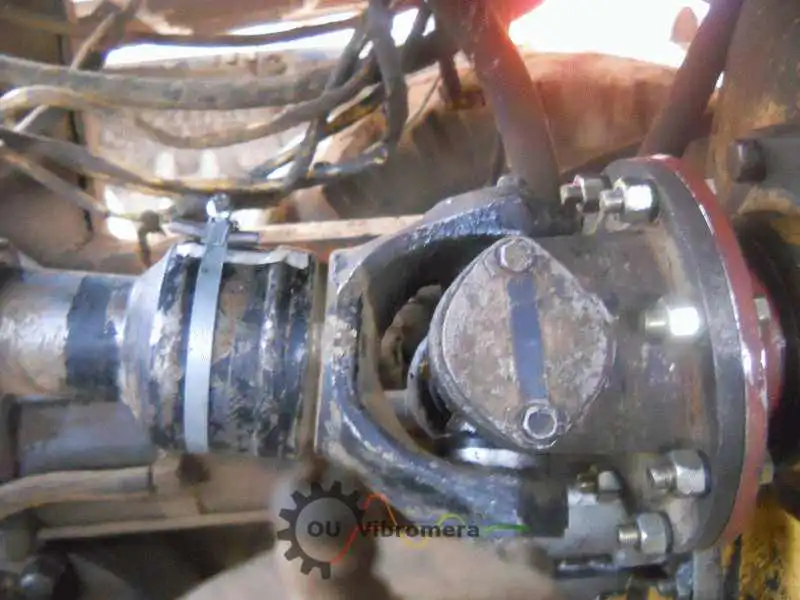
Fig.2 Photo of the cardan with corrective weights installed in planes 1 and 2.
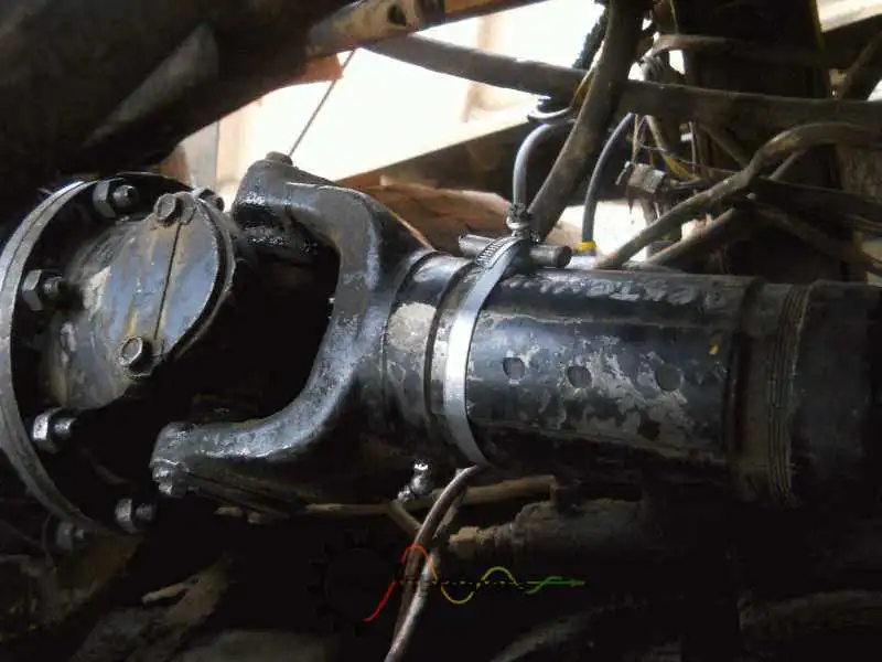
Fig.3. Photo of gimbal with corrective weight in plane 2.
The vibration remains, but it is noticeable in the front of the engine, presumably the drive pulley and the fan. Now the grader is out on combat duty and the experiments have stopped.
I started balancing the flywheel of our second grader and went straight back to the repair. I found axial and radial movement of the crankshaft. After opening opened it showed that grinding is needed.
Please forgive me if I violated the laws of physics, I just did not know that you can do so.
Regards, Andrew.
Reply to Kobyakov’s letters
Andrew, I compared your balancing results with the requirements for these rotors, which are reflected in GOST 22061-76 Machines and technological equipment. Balance quality grade system. General (the modern international counterpart is ISO 21940-11, formerly ISO 1940-1).
I think it will be interesting for you to compare your results with tolerances of this standard.
1. Crankshaft (including clutch basket etc.)
The tolerance should correspond to accuracy class 6 (see appendix 1, page 13).
In this class and at 2000 rpm the permissible residual unbalance values for each plane are between 40 and 100 µm (see diagrams on page 3).
Converted into permissible residual unbalance for your 80 kg rotor, the tolerance is between 3200 and 8000 g*mm.
You have achieved 2600 g*mm.
2. Cardan shaft .
The tolerance should be Class 5 accuracy (see Appendix 1, page 13).
(In the case of the cardan shaft you did not specify the speed, and I took it conditionally at 2000 rpm).
For this class and a rotational speed of 2000 rpm, the permissible residual specific unbalance for each plane is between 15 and 40 µm (see diagrams on page 3).
When converted to a permissible residual unbalance for a 15 kg universal joint shaft, the tolerance ranges from 225 – 600 g*mm.
You managed to achieve 36 g*mm in the first plane and 9 g*mm in the second plane !!!!.
That is impressive.
Regards.
F.V.D.