ਬੈਲੇਂਸਿੰਗ ਸੇਵਾਵਾਂ › ਸਪਿੰਡਲ & ਟੂਲਹੋਲਡਰ
CNC ਸਪਿੰਡਲ & ਟੂਲਹੋਲਡਰ ਬੈਲੇਂਸਿੰਗ — ਓਪਰੇਟਿੰਗ ਸਪੀਡ 'ਤੇ, ਮਸ਼ੀਨ ਵਿੱਚ
ਹਾਈ-ਸਪੀਡ ਮਸ਼ੀਨਿੰਗ ਸਪਿੰਡਲ ਸ਼ੁੱਧ ਯੰਤਰ ਹਨ — 24,000 rpm 'ਤੇ ਮਿਲੀਗ੍ਰਾਮ ਦੇ ਬਰਾਬਰ ਅਸੰਤੁਲਨ ਵੀ ਨੁਕਸਾਨਦੇਹ ਕੇਂਦਰੀ ਬਲ ਪੈਦਾ ਕਰਦਾ ਹੈ। ਅਸੀਂ CNC ਸਪਿੰਡਲਾਂ ਅਤੇ HSK/BT/CAT ਟੂਲਹੋਲਡਰ ਅਸੈਂਬਲੀਆਂ ਦੀ ਬੈਲੇਂਸਿੰਗ ਕਰਦੇ ਹਾਂ ਓਪਰੇਟਿੰਗ ਸਪੀਡ 'ਤੇ, ਮਸ਼ੀਨ ਵਿੱਚ, ਤਾਂ ਜੋ ਸਤ੍ਹਾ ਦੀ ਫਿਨਿਸ਼ ਵਿੱਚ ਸੁਧਾਰ ਹੋਵੇ, ਟੂਲ ਦੀ ਉਮਰ ਵਧੇ, ਅਤੇ ਸਪਿੰਡਲ ਬੇਅਰਿੰਗਾਂ ਕਾਫ਼ੀ ਲੰਬੇ ਸਮੇਂ ਤੱਕ ਚੱਲਣ।
ਸੰਖੇਪ ਵਿੱਚ: CNC ਸਪਿੰਡਲ ਅਤੇ ਟੂਲਹੋਲਡਰ ਬੈਲੇਂਸਿੰਗ ਅਸਲ ਮਸ਼ੀਨਿੰਗ ਸਪੀਡ 'ਤੇ ਮੌਕੇ 'ਤੇ ਕੀਤੀ ਜਾਂਦੀ ਹੈ — ਸਪਿੰਡਲ ਹਟਾਉਣ ਦੀ ਲੋੜ ਨਹੀਂ, ਬੈਲੇਂਸਿੰਗ ਸੈਸ਼ਨ ਤੋਂ ਪਰੇ ਕੋਈ ਮਸ਼ੀਨ ਡਾਊਨਟਾਈਮ ਨਹੀਂ। ਸਪਿੰਡਲ ਹਾਊਜ਼ਿੰਗ 'ਤੇ ਇੱਕ ਵਾਈਬ੍ਰੇਸ਼ਨ ਸੈਂਸਰ ਅਤੇ ਰੋਟੇਟਿੰਗ ਅਸੈਂਬਲੀ 'ਤੇ ਇੱਕ ਲੇਜ਼ਰ ਟੈਕੋਮੀਟਰ Balanset-1A ਨੂੰ ਡੇਟਾ ਭੇਜਦੇ ਹਨ, ਜੋ ਸਹੀ ਕਰੈਕਸ਼ਨ ਮਾਸ ਅਤੇ ਕੋਣੀ ਸਥਿਤੀ ਦੀ ਗਣਨਾ ਕਰਨ ਲਈ ਇੰਫਲੂਐਂਸ-ਕੋਐਫੀਸ਼ੀਐਂਟ ਵਿਧੀ ਲਾਗੂ ਕਰਦਾ ਹੈ। ਪੂਰੀ ਅਸੈਂਬਲੀ — ਟੂਲਹੋਲਡਰ, ਕੋਲਟ, ਅਤੇ ਕਟਿੰਗ ਟੂਲ ਇਕੱਠੇ — ਇੱਕ ਇਕਾਈ ਵਜੋਂ ਬੈਲੇਂਸ ਕੀਤੀ ਜਾਂਦੀ ਹੈ, ISO 21940-11 ਗ੍ਰੇਡ G1.0 ਜਾਂ ਇਸ ਤੋਂ ਬਿਹਤਰ ਪ੍ਰਾਪਤ ਕਰਦੇ ਹੋਏ, ਬਕਾਇਆ ਵਾਈਬ੍ਰੇਸ਼ਨ ਨੂੰ 70 % ਜਾਂ ਵੱਧ ਘਟਾਉਂਦੇ ਹੋਏ ਅਤੇ ਸਪਿੰਡਲ-ਬੇਅਰਿੰਗ ਦੀ ਉਮਰ ਦਸ ਗੁਣਾ ਤੱਕ ਵਧਾਉਂਦੇ ਹੋਏ।
ਸੰਕੇਤ ਕਿ ਤੁਹਾਡਾ ਸਪਿੰਡਲ ਜਾਂ ਟੂਲਹੋਲਡਰ ਅਸੰਤੁਲਿਤ ਹੈ
ਹਾਈ-ਸਪੀਡ ਸਪਿੰਡਲ ਅਸੰਤੁਲਨ ਮਸ਼ੀਨ ਕੀਤੇ ਵਰਕਪੀਸ ਅਤੇ ਸਪਿੰਡਲ ਅਸੈਂਬਲੀ ਖੁਦ ਦੁਆਰਾ ਪ੍ਰਗਟ ਹੁੰਦਾ ਹੈ। ਕੀ ਦੇਖਣਾ ਹੈ ਇਹ ਜਾਣੋ:
ਸਪਿੰਡਲ ਅਤੇ ਟੂਲਹੋਲਡਰ ਸੰਤੁਲਨ ਕਿਉਂ ਗੁਆਉਂਦੇ ਹਨ — ਅਤੇ ਇਸਦੀ ਕੀਮਤ ਕੀ ਹੁੰਦੀ ਹੈ
ਇੱਕ ਸਪਿੰਡਲ ਅਸੈਂਬਲੀ ਟੋਲਰੈਂਸਡ ਭਾਗਾਂ ਦਾ ਇੱਕ ਸਮੂਹ ਹੈ — ਸਪਿੰਡਲ ਸ਼ਾਫਟ, ਡ੍ਰਾਅਬਾਰ, ਟੂਲਹੋਲਡਰ ਟੇਪਰ, ਕੋਲੇਟ, ਅਤੇ ਕੱਟਣ ਵਾਲਾ ਟੂਲ — ਹਰ ਇੱਕ ਆਪਣੀ ਛੋਟੀ ਮਾਸ ਅਸਮਾਨਤਾ ਦਾ ਯੋਗਦਾਨ ਪਾਉਂਦਾ ਹੈ। ਕੁੱਲ ਅਸੰਤੁਲਨ ਇਸ ਲਈ ਮਹੱਤਵਪੂਰਨ ਹੈ ਕਿਉਂਕਿ ਕੇਂਦਰੀਭਾਗੀ ਬਲ ਦੇ ਨਾਲ ਵਧਦਾ ਹੈ ਵਰਗ ਘੁੰਮਣ ਦੀ ਗਤੀ ਦੇ। 10,000 rpm 'ਤੇ ਸਿਰਫ਼ 1 g·mm ਦਾ ਅਸੰਤੁਲਨ ਲਗਭਗ 1 N ਦਾ ਘੁੰਮਣ ਵਾਲਾ ਰੇਡੀਅਲ ਬਲ ਪੈਦਾ ਕਰਦਾ ਹੈ; 30,000 rpm 'ਤੇ ਉਹੀ ਸਮਾਨ 1 g·mm 9 N ਪੈਦਾ ਕਰਦਾ ਹੈ। ਇਹ ਬਲ ਅਗਲੇ ਐਂਗੁਲਰ-ਕੋਂਟੈਕਟ ਬੇਅਰਿੰਗਾਂ ਨੂੰ ਇੱਕ ਸੈਕਟਰ ਵਿੱਚ ਲਗਾਤਾਰ ਲੋਡ ਕਰਦੇ ਹਨ, ਹਰ ਚੱਕਰ ਵਿੱਚ ਬਾਲ ਟ੍ਰੈਕਾਂ ਨੂੰ ਸੰਕੁਚਿਤ ਕਰਦੇ ਹਨ। ਉਤਪਾਦਨ ਸ਼ਿਫਟ ਦੌਰਾਨ ਥਕਾਵਟ ਨੁਕਸਾਨ ਗੰਭੀਰ ਹੁੰਦਾ ਹੈ: ਜੋ ਸਪਿੰਡਲ ਬੇਅਰਿੰਗ ਸਾਲਾਂ ਤੱਕ ਚੱਲਣੀਆਂ ਚਾਹੀਦੀਆਂ ਹਨ ਉਹ ਮਹੀਨਿਆਂ ਵਿੱਚ ਖਰਾਬ ਹੋ ਜਾਂਦੀਆਂ ਹਨ, ਅਤੇ ਅਸੈਂਬਲੀ ਦੌਰਾਨ ਨਿਰਧਾਰਤ ਸ਼ੁੱਧਤਾ ਪ੍ਰੀਲੋਡ ਖਤਮ ਹੋ ਜਾਂਦੀ ਹੈ।
ਸਤ੍ਹਾ-ਗੁਣਵੱਤਾ ਦੀਆਂ ਲਾਗਤਾਂ ਵੀ ਬਰਾਬਰ ਤੇਜ਼ੀ ਨਾਲ ਵਧਦੀਆਂ ਹਨ। ਸਪਿੰਡਲ ਆਵਿਰਤੀ 'ਤੇ ਵਾਈਬ੍ਰੇਸ਼ਨ ਸਤ੍ਹਾ ਦੀ ਲਹਿਰਦਾਰਤਾ ਪੈਦਾ ਕਰਦੀ ਹੈ ਜਿਸ ਲਈ ਵਾਧੂ ਫਿਨਿਸ਼ਿੰਗ ਪਾਸ ਦੀ ਲੋੜ ਹੁੰਦੀ ਹੈ, ਸਕ੍ਰੈਪ ਦਰਾਂ ਵਧਾਉਂਦੀ ਹੈ, ਅਤੇ ਪ੍ਰਾਪਤ ਕੀਤੀਆਂ ਜਾ ਸਕਣ ਵਾਲੀਆਂ ਟੋਲਰੈਂਸਾਂ ਨੂੰ ਸੀਮਤ ਕਰਦੀ ਹੈ। ਏਰੋਸਪੇਸ, ਮੈਡੀਕਲ, ਅਤੇ ਆਪਟੀਕਲ ਪਾਰਟਾਂ ਲਈ, ਸਪਿੰਡਲ ਸੰਤੁਲਨ ਵਿਕਲਪਿਕ ਰੱਖ-ਰਖਾਅ ਨਹੀਂ — ਇਹ ਪ੍ਰਕਿਰਿਆ ਸੈੱਟਅੱਪ ਵਿੱਚ ਇੱਕ ਲਾਜ਼ਮੀ ਕਦਮ ਹੈ। Balanset-1A ਨਾਲ ਉਤਪਾਦਨ ਚੱਲਾਉਣ ਤੋਂ ਪਹਿਲਾਂ ਪੂਰੀ ਅਸੈਂਬਲੀ ਦਾ ਸੰਤੁਲਨ ਇੱਕ ਘੰਟੇ ਤੋਂ ਘੱਟ ਸਮੇਂ ਵਿੱਚ ਹੋ ਜਾਂਦਾ ਹੈ ਅਤੇ ਨਿਵੇਸ਼ ਬਚੇ ਹੋਏ ਟੂਲਿੰਗ ਦੇ ਇੱਕ ਦਿਨ ਵਿੱਚ ਵਾਪਸ ਮਿਲ ਜਾਂਦਾ ਹੈ।
ਵਾਈਬ੍ਰੇਸ਼ਨ ਅੱਧੀ ਕਰਨ ਨਾਲ ਬੇਅਰਿੰਗ ਦੀ ਉਮਰ ਕਈ ਗੁਣਾ ਕਿਉਂ ਵਧਦੀ ਹੈ
CNC ਸਪਿੰਡਲ ਦਾ ਸੰਤੁਲਨ ਕਿਵੇਂ ਕਰੀਏ — ਕਦਮ ਦਰ ਕਦਮ
Balanset-1A ਨਾਲ CNC ਸਪਿੰਡਲ ਦਾ ਫੀਲਡ ਸੰਤੁਲਨ ਪ੍ਰਭਾਵ-ਗੁਣਾਂਕ ਵਿਧੀ ਦੀ ਵਰਤੋਂ ਕਰਕੇ ਅਸਲ ਮਸ਼ੀਨਿੰਗ ਗਤੀ 'ਤੇ, ਮਸ਼ੀਨ ਦੇ ਅੰਦਰ ਹੀ ਕੀਤਾ ਜਾਂਦਾ ਹੈ — ਕੋਈ ਵੱਖ ਕਰਨ ਦੀ ਲੋੜ ਨਹੀਂ:
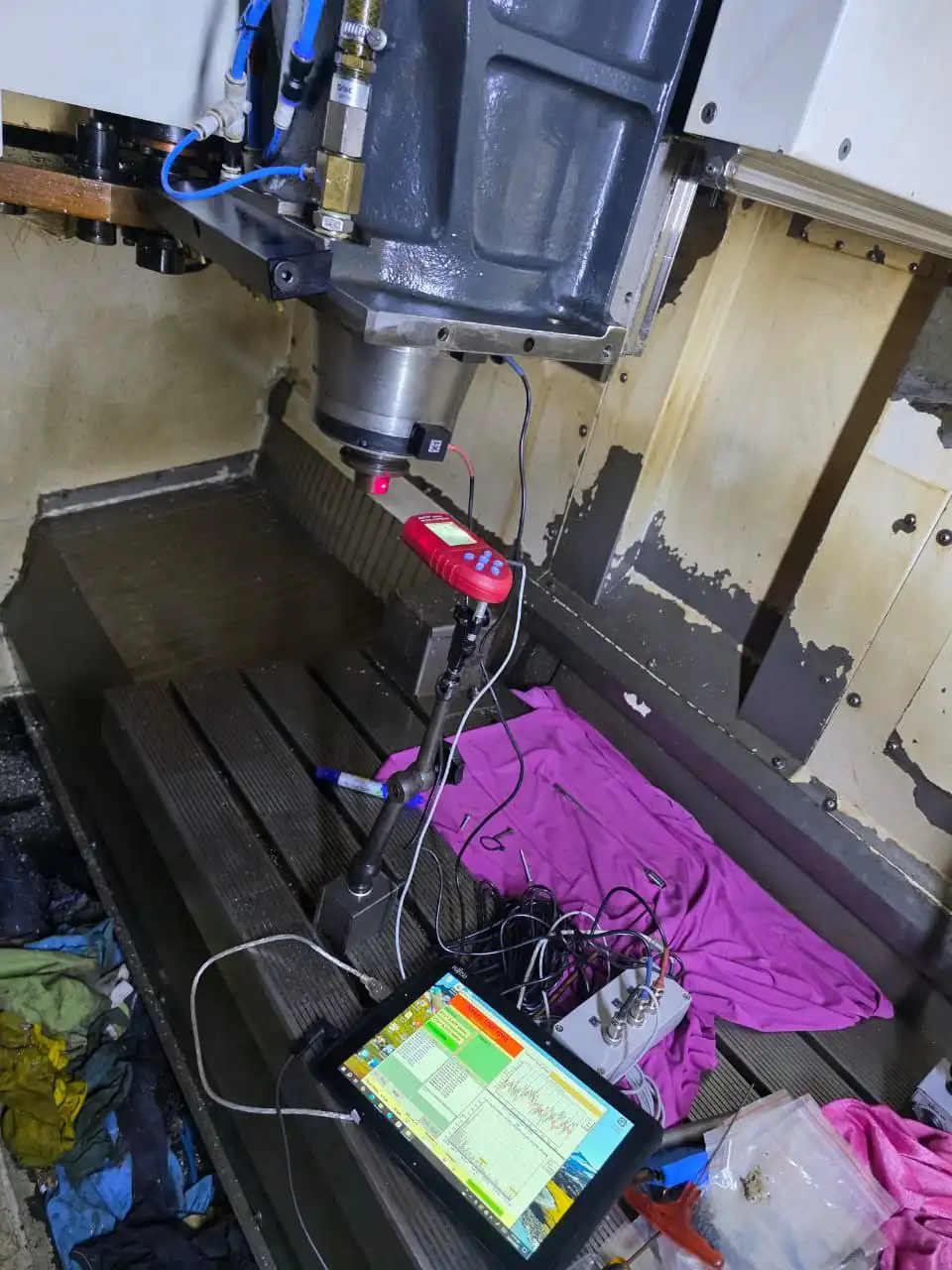
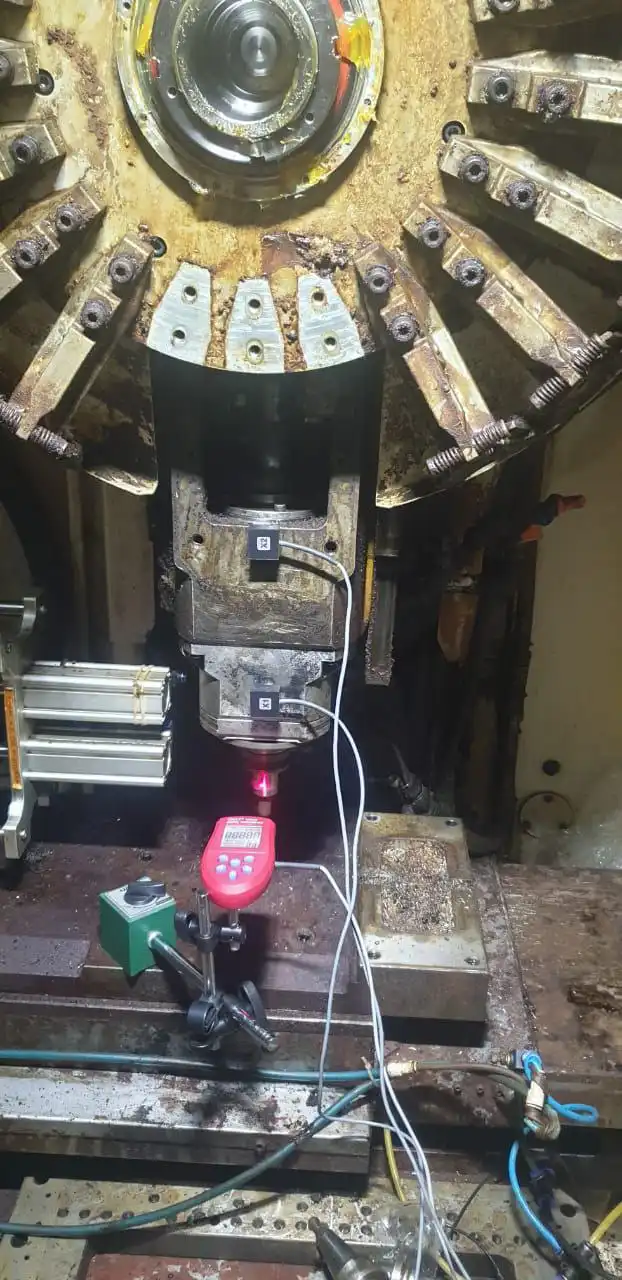
- ਸੈਂਸਰ ਲਗਾਓ। ਇੱਕ ਵਾਈਬ੍ਰੇਸ਼ਨ ਐਕਸੀਲੇਰੋਮੀਟਰ ਅਗਲੇ-ਬੇਅਰਿੰਗ ਖੇਤਰ ਵਿੱਚ ਸਪਿੰਡਲ ਹਾਊਜ਼ਿੰਗ ਨਾਲ ਸਥਿਰ ਕੀਤਾ ਜਾਂਦਾ ਹੈ ਅਤੇ ਇੱਕ ਲੇਜ਼ਰ ਟੈਕੋਮੀਟਰ ਟੂਲਹੋਲਡਰ ਜਾਂ ਸਪਿੰਡਲ ਨੋਜ਼ 'ਤੇ ਰਿਫਲੈਕਟਿਵ ਫੇਜ਼ ਸਟ੍ਰਿਪ ਵੱਲ ਸੇਧਿਤ ਕੀਤਾ ਜਾਂਦਾ ਹੈ। ਮਸ਼ੀਨ ਪੂਰੇ ਸਮੇਂ ਦੌਰਾਨ ਜੋੜੀ ਹੋਈ ਅਤੇ ਆਪਣੀ ਆਮ ਕਾਰਜਸ਼ੀਲ ਸਥਿਤੀ ਵਿੱਚ ਰਹਿੰਦੀ ਹੈ।
- ਬੇਸਲਾਈਨ ਮਾਪ ਲਓ। ਟਾਰਗੇਟ ਮਸ਼ੀਨਿੰਗ ਗਤੀ 'ਤੇ ਇੱਕ ਰਨ ਵਾਈਬ੍ਰੇਸ਼ਨ ਐਂਪਲੀਟਿਊਡ ਅਤੇ ਫੇਜ਼ ਕੋਣ ਕੈਪਚਰ ਕਰਦਾ ਹੈ, ਜੋ ਪੂਰੀ ਘੁੰਮਣ ਵਾਲੀ ਅਸੈਂਬਲੀ ਲਈ ਮਿਕਦਾਰ ਅਤੇ ਦਿਸ਼ਾ ਦੋਵਾਂ ਵਿੱਚ ਮੌਜੂਦਾ ਅਸੰਤੁਲਨ ਅਵਸਥਾ ਸਥਾਪਿਤ ਕਰਦਾ ਹੈ।
- ਟ੍ਰਾਇਲ ਵੇਟ ਲਗਾਓ। ਟੂਲਹੋਲਡਰ ਦੀ ਬੈਲੇਂਸ ਰਿੰਗ ਉੱਤੇ, ਜਾਂ ਸਪਿੰਡਲ ਨੋਜ਼ ਦੀ ਵਿਸ਼ੇਸ਼ ਬੈਲੇਂਸਿੰਗ ਫਲੈਂਜ ਉੱਤੇ, ਇੱਕ ਛੋਟਾ ਜਿਹਾ ਕੈਲੀਬ੍ਰੇਟਿਡ ਭਾਰ ਲਗਾਇਆ ਜਾਂਦਾ ਹੈ। ਉਸੇ ਗਤੀ 'ਤੇ ਦੂਜਾ ਰਨ ਕਰਨ ਨਾਲ ਉਸ ਕੋਣੀ ਸਥਿਤੀ 'ਤੇ ਇੱਕ ਜਾਣੀ-ਪਛਾਣੀ ਗੜਬੜੀ ਪ੍ਰਤੀ ਸਪਿੰਡਲ ਦੀ ਪ੍ਰਤੀਕਿਰਿਆ — ਪ੍ਰਭਾਵ ਗੁਣਾਂਕ (influence coefficient) — ਮਾਪੀ ਜਾਂਦੀ ਹੈ।
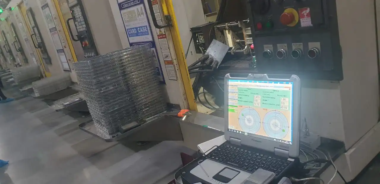
- ਉਪਕਰਨ ਨੂੰ ਗਣਨਾ ਕਰਨ ਦਿਓ। Balanset-1A ਪ੍ਰਭਾਵ-ਗੁਣਾਂਕ ਸਮੀਕਰਨਾਂ ਨੂੰ ਹੱਲ ਕਰਕੇ ਸੁਧਾਰ ਭਾਰ ਅਤੇ ਇਸਦੀ ਸਟੀਕ ਕੋਣੀ ਸਥਿਤੀ ਦੱਸਦਾ ਹੈ। ਲੰਮੀਆਂ ਅਸੈਂਬਲੀਆਂ ਲਈ, ਜਾਂ ਜਦੋਂ ਟੂਲਹੋਲਡਰ ਸਤਹ ਅਤੇ ਸਪਿੰਡਲ-ਨੋਜ਼ ਸਤਹ — ਦੋਵੇਂ — ਪਹੁੰਚਯੋਗ ਹੋਣ, ਦੋ-ਸਤਹ ਬੈਲੇਂਸਿੰਗ ਸਟੈਟਿਕ ਅਸੰਤੁਲਨ ਦੇ ਨਾਲ-ਨਾਲ ਕਪਲ ਅਸੰਤੁਲਨ ਨੂੰ ਵੀ ਖਤਮ ਕਰਦੀ ਹੈ।
- ਸੁਧਾਰ ਲਗਾਓ। ਬੈਲੇਂਸ ਰਿੰਗ 'ਤੇ ਐਡਜਸਟਮੈਂਟ ਪੇਚ, ਟੂਲਹੋਲਡਰ ਫਲੈਂਜ ਦੀ ਸ਼ੁੱਧ ਗ੍ਰਾਈਂਡਿੰਗ, ਜਾਂ ਵਿਸ਼ੇਸ਼ ਕਲਿੱਪ ਭਾਰ — ਦੱਸੇ ਗਏ ਕੋਣ 'ਤੇ ਗਣਨਾ ਕੀਤਾ ਸੁਧਾਰ ਲਾਗੂ ਕਰਦੇ ਹਨ। ਟ੍ਰਾਇਲ ਭਾਰ ਹਟਾ ਦਿੱਤਾ ਜਾਂਦਾ ਹੈ, ਜਦੋਂ ਤੱਕ ਕਿ ਉਹ ਅੰਤਿਮ ਸੁਧਾਰ ਦਾ ਹਿੱਸਾ ਨਾ ਬਣੇ।
- ਤਸਦੀਕ ਕਰੋ ਅਤੇ ਦਸਤਾਵੇਜ਼ੀਕਰਨ ਕਰੋ। ਓਪਰੇਟਿੰਗ ਗਤੀ 'ਤੇ ਅੰਤਿਮ ਮਾਪ ਰਨ ਇਹ ਪੁਸ਼ਟੀ ਕਰਦਾ ਹੈ ਕਿ ਬਾਕੀ ਅਸੰਤੁਲਨ ਸਪਿੰਡਲ ਦੇ ਭਾਰ ਅਤੇ ਗਤੀ ਲਈ G2.5 ਜਾਂ G1.0 ਸਹਿਣਸ਼ੀਲਤਾ ਦੇ ਅੰਦਰ ਹੈ। Balanset-1A ਤੁਹਾਡੇ ਗੁਣਵੱਤਾ ਰਿਕਾਰਡਾਂ ਲਈ ਪਹਿਲਾਂ ਅਤੇ ਬਾਅਦ ਦੇ ਮੁੱਲਾਂ ਸਮੇਤ ਟਾਈਮਸਟੈਂਪਡ ਰਿਪੋਰਟ ਸੁਰੱਖਿਅਤ ਕਰਦਾ ਹੈ।
ਅਸੀਂ ਕੀ ਬੈਲੇਂਸ ਕਰਦੇ ਹਾਂ
- HSK ਟੂਲਹੋਲਡਰ ਅਸੈਂਬਲੀਆਂ (HSK-A25 ਤੋਂ HSK-A100) ਟੂਲ ਸਮੇਤ
- BT ਅਤੇ CAT / ISO ਟੇਪਰ ਟੂਲਹੋਲਡਰ (BT30, BT40, BT50, CAT40, CAT50)
- ਕੋਲੇਟ ਚੱਕ ਅਤੇ ER ਕੋਲੇਟ ਅਸੈਂਬਲੀਆਂ
- ਫੇਸ-ਮਿਲਿੰਗ ਆਰਬਰ ਅਤੇ ਸ਼ੈੱਲ-ਮਿੱਲ ਅਡੈਪਟਰ
- ਬੋਰਿੰਗ ਹੈੱਡ ਅਤੇ ਸ਼ੁੱਧਤਾ ਬੋਰਿੰਗ ਬਾਰ
- CNC ਮਸ਼ੀਨਿੰਗ-ਸੈਂਟਰ ਸਪਿੰਡਲ ਸ਼ਾਫਟ
- ਗ੍ਰਾਈਂਡਿੰਗ ਵ੍ਹੀਲ ਸਪਿੰਡਲ ਅਸੈਂਬਲੀਆਂ
- ਉੱਚ-ਆਵਿਰਤੀ ਰਾਊਟਰ ਅਤੇ ਐਨਗ੍ਰੇਵਿੰਗ ਸਪਿੰਡਲ
- ਟਰਨਿੰਗ-ਸੈਂਟਰ ਲਾਈਵ-ਟੂਲਿੰਗ ਯੂਨਿਟਾਂ
- Direct-drive motorised spindles (balancing runs at up to ~60,000 rpm, within the instrument’s 5–1000 Hz measurement range; best accuracy up to ~33,000 rpm)
ਸਹਿਣਸ਼ੀਲਤਾਵਾਂ & ਮਿਆਰ
ISO 21940-11 (ਪਹਿਲਾਂ ISO 1940-1) ਰਿਜਿੱਡ ਰੋਟਰਾਂ ਲਈ G0.4 ਤੋਂ G4000 ਤੱਕ ਬੈਲੇਂਸ ਗੁਣਵੱਤਾ ਗ੍ਰੇਡ ਪਰਿਭਾਸ਼ਿਤ ਕਰਦਾ ਹੈ। ਮਸ਼ੀਨਿੰਗ ਸਪਿੰਡਲਾਂ ਅਤੇ ਟੂਲਹੋਲਡਰਾਂ ਲਈ ਲਾਗੂ ਗ੍ਰੇਡ ਹਨ G2.5 (ਆਮ ਮਸ਼ੀਨਿੰਗ ~10,000 rpm ਤੱਕ) ਅਤੇ G1.0 (ਸ਼ੁੱਧਤਾ ਅਤੇ ਉੱਚ-ਗਤੀ ਸਪਿੰਡਲ 10,000 rpm ਤੋਂ ਉੱਪਰ)। ਅਧਿਕਤਮ ਬਾਕੀ ਅਸੰਤੁਲਨ Uਪ੍ਰਤੀ = eਪ੍ਰਤੀ × m (g·mm), ਜਿੱਥੇ eਪ੍ਰਤੀ G-ਗ੍ਰੇਡ ਅਤੇ ਰੋਟੇਸ਼ਨਲ ਗਤੀ ਤੋਂ ਪ੍ਰਾਪਤ ਵਿਸ਼ੇਸ਼ ਅਸੰਤੁਲਨ ਹੈ, ਅਤੇ m ਰੋਟਰ ਦਾ ਭਾਰ kg ਵਿੱਚ ਹੈ।
For high-speed machining assemblies, acceptance criteria beyond the ISO 21940-11 balance tolerance are set by the spindle and toolholder manufacturers’ own specifications. Good practice requires that the ਪੂਰੀ ਅਸੈਂਬਲੀ — ਟੂਲਹੋਲਡਰ, ਕੋਲੇਟ, ਅਤੇ ਲੱਗਾ ਕੱਟਣ ਵਾਲਾ ਸੰਦ — ਨੂੰ ਇੱਕ ਇਕਾਈ ਵਜੋਂ ਸੰਤੁਲਿਤ ਕੀਤਾ ਜਾਵੇ, ਕਿਉਂਕਿ ਹਰੇਕ ਤੱਤ ਆਪਣੀ ਵੱਖਰੀ ਪੁੰਜ ਅਸਮਾਨਤਾ ਵਿੱਚ ਯੋਗਦਾਨ ਪਾਉਂਦਾ ਹੈ। ਅਸੀਂ g·mm ਵਿੱਚ ਬਚੇ ਹੋਏ ਅਸੰਤੁਲਨ ਨੂੰ ਮਾਪਦੇ ਅਤੇ ਦਸਤਾਵੇਜ਼ੀਕਰਨ ਕਰਦੇ ਹਾਂ ਅਤੇ ਤੁਹਾਡੀ ਐਪਲੀਕੇਸ਼ਨ ਦੀ ਮੰਗ ਅਨੁਸਾਰ ਗ੍ਰੇਡ ਲਈ ਬੈਲੇਂਸਿੰਗ ਰਿਪੋਰਟ ਪ੍ਰਦਾਨ ਕਰਦੇ ਹਾਂ। ਸਾਡਾ ਉਪਯੋਗ ਕਰੋ ਬਾਕੀ-ਬਚੇ ਅਸੰਤੁਲਨ ਕੈਲਕੁਲੇਟਰ ਸ਼ੁਰੂ ਕਰਨ ਤੋਂ ਪਹਿਲਾਂ ਮਨਜ਼ੂਰਸ਼ੁਦਾ ਸਹਿਣਸ਼ੀਲਤਾ ਦਾ ਪਤਾ ਲਗਾਉਣ ਲਈ।
Balanset-1A — ਤੁਹਾਡੀ ਸੰਪੂਰਨ ਸਾਈਟ-ਬੈਲੇਂਸਿੰਗ ਕਿੱਟ
ਇਸ ਪੰਨੇ 'ਤੇ ਸਭ ਕੁਝ ਇੱਕ ਪੋਰਟੇਬਲ ਯੰਤਰ ਨਾਲ ਕੀਤਾ ਜਾਂਦਾ ਹੈ: Balanset-1A। ਇਹ ਇੱਕ ਦੋ-ਚੈਨਲ ਡਾਇਨਾਮਿਕ ਬੈਲੇਂਸਰ ਅਤੇ ਵਾਈਬ੍ਰੇਸ਼ਨ ਵਿਸ਼ਲੇਸ਼ਕ ਹੈ ਜੋ CNC ਸਪਿੰਡਲ ਅਤੇ ਟੂਲਹੋਲਡਰ ਅਸੈਂਬਲੀਆਂ ਨੂੰ ਸੰਤੁਲਿਤ ਕਰਦਾ ਹੈ ਆਪਣੇ ਬੇਅਰਿੰਗਾਂ ਵਿੱਚ, ਓਪਰੇਟਿੰਗ ਗਤੀ 'ਤੇ, 3-ਰਨ ਪ੍ਰਭਾਵ-ਗੁਣਾਂਕ ਵਿਧੀ ਦੀ ਵਰਤੋਂ ਕਰਕੇ — ਸੌਫ਼ਟਵੇਅਰ ਸਹੀ ਸੁਧਾਰ ਪੁੰਜ ਅਤੇ ਕੋਣ ਦੀ ਗਣਨਾ ਕਰਦਾ ਹੈ ਅਤੇ ਇੱਕ ਰਿਪੋਰਟ ਸੁਰੱਖਿਅਤ ਕਰਦਾ ਹੈ।
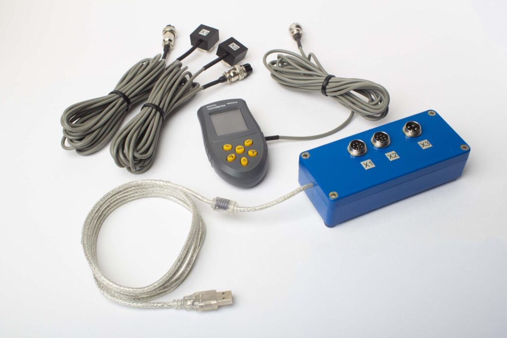
ਪੂਰੇ ਕਿੱਟ ਵਿੱਚ ਕੀ ਸ਼ਾਮਲ ਹੈ
€1,975 · ਪੂਰਾ ਕਿੱਟ, ਸਟਾਕ ਵਿੱਚ, VAT ਇਨਵੌਇਸ
- ਇੰਟਰਫੇਸ ਮਾਪ ਇਕਾਈ (USB, 2 ਚੈਨਲ)
- ਦੋ ਵਾਈਬ੍ਰੇਸ਼ਨ ਐਕਸੇਲੇਰੋਮੀਟਰ (4 m ਕੇਬਲ, 10 m ਵਿਕਲਪਿਕ)
- ਲੇਜ਼ਰ ਟੈਕੋਮੀਟਰ / ਆਪਟੀਕਲ ਫੇਜ਼ ਸੈਂਸਰ (50–500 mm)
- ਸੈਂਸਰ ਲਈ ਮੈਗਨੈਟਿਕ ਸਟੈਂਡ
- ਟਰਾਇਲ & ਸੁਧਾਰ ਵਜ਼ਨ ਲਈ ਡਿਜੀਟਲ ਸਕੇਲ
- Windows ਬੈਲੇਂਸਿੰਗ & ਵਿਸ਼ਲੇਸ਼ਣ ਸੌਫ਼ਟਵੇਅਰ
- ਪਲਾਸਟਿਕ ਟਰਾਂਸਪੋਰਟ ਕੇਸ
ਪੂਰੀ ਕਿੱਟ
ਇਕਾਈ · 2 ਸੈਂਸਰ · ਲੇਜ਼ਰ ਟੈਕੋਮੀਟਰ · ਮੈਗਨੈਟਿਕ ਸਟੈਂਡ · ਡਿਜੀਟਲ ਸਕੇਲ · ਸੌਫ਼ਟਵੇਅਰ · ਟਰਾਂਸਪੋਰਟ ਕੇਸ। ਬਾਕਸ ਤੋਂ ਬਾਹਰ ਬੈਲੇਂਸਿੰਗ ਸ਼ੁਰੂ ਕਰਨ ਲਈ ਸਭ ਕੁਝ ਲੋੜੀਂਦਾ।
OEM ਸੈੱਟ
ਇਕਾਈ · 2 ਸੈਂਸਰ · ਲੇਜ਼ਰ ਟੈਕੋਮੀਟਰ · ਸੌਫ਼ਟਵੇਅਰ। ਉਹਨਾਂ ਇੰਟੀਗ੍ਰੇਟਰਾਂ ਲਈ ਜਿਨ੍ਹਾਂ ਕੋਲ ਪਹਿਲਾਂ ਤੋਂ ਸਟੈਂਡ, ਸਕੇਲ ਅਤੇ ਕੇਸ ਹੈ, ਜਾਂ ਜੋ ਇਕਾਈ ਨੂੰ ਬੈਲੇਂਸਿੰਗ ਮਸ਼ੀਨ ਵਿੱਚ ਏਮਬੈੱਡ ਕਰਦੇ ਹਨ।
| ਪੈਰਾਮੀਟਰ | ਮੁੱਲ |
|---|---|
| ਮਾਪ ਚੈਨਲ | 2 (ਸਿੰਗਲ- & ਟੂ-ਪਲੇਨ ਬੈਲੇਂਸਿੰਗ) |
| ਵਾਈਬ੍ਰੇਸ਼ਨ ਵੇਲੋਸਿਟੀ ਰੇਂਜ | 0.2–80 mm/s RMS |
| ਫ੍ਰੀਕੁਐਂਸੀ ਰੇਂਜ | 5–1000 Hz (≤10% ਐਪਲੀਟਿਊਡ ਗਲਤੀ 550 Hz ਤੋਂ ਉੱਪਰ) |
| ਮਾਪ ਸ਼ੁੱਧਤਾ | ±5% ਪੂਰੇ ਸਕੇਲ ਦਾ |
| ਵਿਧੀ | 3-ਰਨ ਇਨਫਲੂਐਂਸ-ਕੋਏਫੀਸ਼ੀਐਂਟ (1 ਜਾਂ 2 ਸੁਧਾਰ-ਪਲੇਨ) |
| ਵਿਸ਼ਲੇਸ਼ਣ | 1× 'ਤੇ ਐਂਪਲੀਟਿਊਡ & ਫੇਜ਼, FFT ਸਪੈਕਟ੍ਰਮ & ਵੇਵਫਾਰਮ, ਸੁਰੱਖਿਅਤ ਰਿਪੋਰਟਾਂ |
| ਲੈਪਟਾਪ | ਸ਼ਾਮਲ ਨਹੀਂ (Windows PC, ਬੇਨਤੀ 'ਤੇ ਉਪਲਬਧ) |
ਸਾਈਟ 'ਤੇ ਸੰਤੁਲਨ ਬਨਾਮ ਬੈਲੇਂਸਿੰਗ ਮਸ਼ੀਨ — ਤੁਹਾਡੇ ਸਪਿੰਡਲ ਲਈ ਕਿਹੜਾ ਸਹੀ ਹੈ?
| ਫੈਕਟਰ | ਫੀਲਡ ਬੈਲੇਂਸਿੰਗ (Balanset-1A) | ਸਮਰਪਿਤ ਬੈਲੇਂਸਿੰਗ ਸਟੈਂਡ (ਵਰਕਸ਼ਾਪ) |
|---|---|---|
| ਕੀ ਸਪਿੰਡਲ ਮਸ਼ੀਨ ਤੋਂ ਹਟਾਇਆ ਗਿਆ ਹੈ? | ਨਹੀਂ — ਆਪਣੀ ਥਾਂ 'ਤੇ ਚੱਲਦਾ ਹੈ | ਹਾਂ — ਪੂਰੀ ਵੱਖ ਕਰਨ ਦੀ ਲੋੜ ਹੈ |
| ਕੀ ਅਸਲ ਚੱਲਣ ਦੀਆਂ ਸਥਿਤੀਆਂ ਨੂੰ ਦਰਸਾਉਂਦਾ ਹੈ? | ਹਾਂ — ਅਸਲ ਬੇਅਰਿੰਗਾਂ, ਥਰਮਲ ਪ੍ਰੀਲੋਡ, ਡਰਾਅਬਾਰ ਕਲੈਂਪਿੰਗ | ਨਹੀਂ — ਵੱਖਰੀ ਸਪਿੰਡਲ ਐਮੂਲੇਸ਼ਨ |
| ਮਸ਼ੀਨ ਬੰਦ ਰਹਿਣ ਦਾ ਸਮਾਂ | ਸਿਰਫ਼ ਸੈਂਸਰ ਲਗਾਉਣਾ (<15 ਮਿੰਟ) | ਘੰਟਿਆਂ ਤੋਂ ਦਿਨਾਂ ਤੱਕ (ਹਟਾਓ, ਭੇਜੋ, ਸੰਤੁਲਿਤ ਕਰੋ, ਮੁੜ ਸਥਾਪਿਤ ਕਰੋ) |
| ਬੈਲੇਂਸਿੰਗ ਗਤੀ | ਅਸਲ ਮਸ਼ੀਨਿੰਗ ਗਤੀ | ਵੱਖਰੀ, ਅਕਸਰ ਘੱਟ, ਟੈਸਟ ਗਤੀ |
| ਕੀ ਪੂਰੀ ਅਸੈਂਬਲੀ (ਹੋਲਡਰ + ਕੋਲੇਟ + ਸੰਦ) ਨੂੰ ਧਿਆਨ ਵਿੱਚ ਰੱਖਦਾ ਹੈ? | ਹਾਂ — ਪੂਰੀ ਅਸੈਂਬਲੀ ਨੂੰ ਇੱਕ ਇਕਾਈ ਵਜੋਂ ਸੰਤੁਲਿਤ ਕੀਤਾ ਗਿਆ | ਸਟੈਂਡ 'ਤੇ ਨਿਰਭਰ ਕਰਦਾ ਹੈ; ਅਕਸਰ ਸਿਰਫ਼ ਹੋਲਡਰ |
| ਪੂਰੇ ਕੀਤੇ ਗਏ ਮਿਆਰ | ISO 21940-11 G1.0 | ISO 21940-11 G1.0 |
| ਉਪਕਰਣ ਦੀ ਲਾਗਤ | €1,975 (ਪੂਰਾ ਕਿੱਟ) | €5,000 – €30,000+ |
| ਪ੍ਰਤੀ ਅਸੈਂਬਲੀ ਆਮ ਕੰਮ ਦਾ ਸਮਾਂ | ਸਾਈਟ 'ਤੇ <1 ਘੰਟਾ | ਕੁੱਲ ਕਈ ਘੰਟੇ ਤੋਂ 1–2 ਦਿਨ |
ਉਤਪਾਦਨ ਸਪਿੰਡਲਾਂ ਲਈ ਜੋ ਚੱਲ ਸਕਦੇ ਹਨ, ਸਥਾਨ 'ਤੇ ਫੀਲਡ ਬੈਲੇਂਸਿੰਗ ਤਰਜੀਹੀ ਤਰੀਕਾ ਹੈ, ਕਿਉਂਕਿ ਇਹ ਅਸਲ ਅਸੈਂਬਲ ਚੱਲਣ ਦੀ ਸਥਿਤੀ ਨੂੰ ਦਰਸਾਉਂਦਾ ਹੈ — ਜਿਸ ਵਿੱਚ ਥਰਮਲ ਪ੍ਰੀਲੋਡ ਅਤੇ ਡਰਾਬਾਰ ਕਲੈਂਪਿੰਗ ਫੋਰਸਾਂ ਸ਼ਾਮਲ ਹਨ — ਜਿਨ੍ਹਾਂ ਨੂੰ ਕੋਈ ਵੱਖਰਾ ਸਟੈਂਡ ਦੁਹਰਾ ਨਹੀਂ ਸਕਦਾ। ਨਵੇਂ ਟੂਲਹੋਲਡਰਾਂ ਲਈ ਪਹਿਲੀ ਵਰਤੋਂ ਤੋਂ ਪਹਿਲਾਂ ਜਾਂ ਬਹੁਤ ਹਾਈ-ਸਪੀਡ ਸਪਿੰਡਲਾਂ ਲਈ ਜਿਨ੍ਹਾਂ ਦੀ ਜਿਓਮੈਟਰੀ ਸਿੱਧੀ ਸੈਂਸਰ ਅਟੈਚਮੈਂਟ ਨੂੰ ਰੋਕਦੀ ਹੈ, ਇੱਕ ਵੱਖਰਾ ਸਟੈਂਡ ਅਜੇ ਵੀ ਉਪਯੋਗੀ ਰਹਿੰਦਾ ਹੈ।
ਅਸਲ ਸਪਿੰਡਲ-ਬੈਲੇਂਸਿੰਗ ਕੇਸ

CNC ਸਪਿੰਡਲ & HSK ਟੂਲਹੋਲਡਰ
ਮਸ਼ੀਨਿੰਗ-ਸੈਂਟਰ ਸਪਿੰਡਲ ਅਤੇ HSK ਟੂਲਹੋਲਡਰ ਅਸੈਂਬਲੀ ਦੀ ਓਪਰੇਟਿੰਗ ਸਪੀਡ 'ਤੇ ਸਥਾਨ 'ਤੇ ਬੈਲੇਂਸਿੰਗ, G1.0 ਰੈਜ਼ੀਡਿਊਅਲ ਅਨਬੈਲੇਂਸ ਪ੍ਰਾਪਤ ਕਰਕੇ ਅਤੇ ਸਤਹ-ਫਿਨਿਸ਼ ਸਮੱਸਿਆਵਾਂ ਨੂੰ ਖਤਮ ਕਰਕੇ।
ਪੂਰੀ ਅਸੈਂਬਲੀ ਨੂੰ ਇੱਕ ਇਕਾਈ ਵਜੋਂ ਬੈਲੇਂਸ ਕੀਤਾ ਗਿਆ
ਪੂਰੀ ਅਸੈਂਬਲੀ — ਹੋਲਡਰ, ਕੋਲੇਟ ਅਤੇ ਟੂਲ — ਨੂੰ ਮਸ਼ੀਨ ਵਿੱਚ ਇਕੱਠੇ ਬੈਲੇਂਸ ਕੀਤਾ ਜਾਂਦਾ ਹੈ। ਹਰੇਕ ਕੰਪੋਨੈਂਟ ਆਪਣੀ ਖੁਦ ਦੀ ਮਾਸ ਅਸਿਮੈਟਰੀ ਯੋਗਦਾਨ ਪਾਉਂਦਾ ਹੈ; ਅਸੈਂਬਲੀ-ਪੱਧਰੀ ਬੈਲੇਂਸਿੰਗ ISO 21940-11 ਦੁਆਰਾ ਲੋੜੀਂਦੀ ਹੈ।
ਅਗਲੇ-ਬੇਅਰਿੰਗ ਖੇਤਰ 'ਤੇ ਸੈਂਸਰ
ਵਾਈਬ੍ਰੇਸ਼ਨ ਐਕਸੀਲੇਰੋਮੀਟਰ ਸਿੱਧਾ ਸਪਿੰਡਲ ਹਾਊਸਿੰਗ 'ਤੇ ਅਗਲੇ ਬੇਅਰਿੰਗ ਕੋਲ ਫਿਕਸ ਕੀਤਾ ਜਾਂਦਾ ਹੈ, ਪੂਰੀ ਮਸ਼ੀਨਿੰਗ ਸਪੀਡ 'ਤੇ ਮਾਪਦਾ ਹੈ — ਸਪਿੰਡਲ ਨੂੰ ਖੋਲ੍ਹਣ ਦੀ ਲੋੜ ਨਹੀਂ।
ਮੁਫ਼ਤ ਸਪਿੰਡਲ & ਟੂਲਹੋਲਡਰ ਕੈਲਕੁਲੇਟਰ
ਸਿਧਾਂਤ ਸਿੱਖੋ
ਸਪਿੰਡਲ & ਟੂਲਹੋਲਡਰ ਬੈਲੇਂਸਿੰਗ FAQ
ਕੀ ਬੈਲੇਂਸਿੰਗ ਲਈ ਸਪਿੰਡਲ ਨੂੰ ਮਸ਼ੀਨ ਤੋਂ ਕੱਢਣਾ ਜ਼ਰੂਰੀ ਹੈ?
ਕੀ ਮੈਨੂੰ ਟੂਲਹੋਲਡਰ ਨੂੰ ਇਕੱਲੇ ਜਾਂ ਪੂਰੀ ਅਸੈਂਬਲੀ ਨੂੰ ਬੈਲੇਂਸ ਕਰਨਾ ਚਾਹੀਦਾ ਹੈ?
ਮਸ਼ੀਨਿੰਗ ਸਪਿੰਡਲਾਂ ਨੂੰ ਕਿਹੜੀ ਬੈਲੇਂਸ ਗ੍ਰੇਡ ਦੀ ਲੋੜ ਹੈ?
ਟੂਲਹੋਲਡਰ ਅਸੈਂਬਲੀਆਂ ਨੂੰ ਕਿੰਨੀ ਵਾਰ ਬੈਲੇਂਸ ਕਰਨਾ ਚਾਹੀਦਾ ਹੈ?
ਕੀ Balanset-1A 20,000 rpm ਤੋਂ ਵੱਧ ਸਪਿੰਡਲ ਗਤੀ ਸੰਭਾਲ ਸਕਦਾ ਹੈ?
ਕੀ ਇੱਕ ਕਰੈਕਸ਼ਨ ਪਲੇਨ ਕਾਫ਼ੀ ਹੈ, ਜਾਂ ਮੈਨੂੰ ਦੋ ਦੀ ਲੋੜ ਹੈ?
ਆਪਣੀ CNC ਸਪਿੰਡਲ ਅਸੈਂਬਲੀ ਨੂੰ ਬੈਲੇਂਸ ਕਰੋ — ਓਪਰੇਟਿੰਗ ਗਤੀ 'ਤੇ, ਮਸ਼ੀਨ ਵਿੱਚ ਹੀ
Balanset-1A ਬਿਨਾਂ ਡਿਸਅਸੈਂਬਲੀ ਦੇ ਓਪਰੇਟਿੰਗ ਗਤੀ 'ਤੇ ਸਪਿੰਡਲ ਅਸੰਤੁਲਨ ਮਾਪਦਾ ਅਤੇ ਹੱਲ ਕਰਦਾ ਹੈ, ISO 21940-11 G1.0 ਟੌਲਰੈਂਸ ਹਾਸਲ ਕਰਦਾ ਹੈ ਅਤੇ ਤੁਹਾਡੇ ਗੁਣਵੱਤਾ ਰਿਕਾਰਡਾਂ ਲਈ ਨਤੀਜਾ ਦਸਤਾਵੇਜ਼ੀ ਕਰਦਾ ਹੈ। ਕੋਈ ਮਸ਼ੀਨ ਹਟਾਉਣੀ ਨਹੀਂ, ਕੋਈ ਉਤਪਾਦਨ ਨੁਕਸਾਨ ਨਹੀਂ — ਬੱਸ ਸ਼ਾਂਤ ਸਪਿੰਡਲ, ਬੇਅਰਿੰਗ ਦੀ ਲੰਮੀ ਉਮਰ, ਅਤੇ ਬਿਹਤਰ ਸਰਫੇਸ ਫਿਨਿਸ਼।
