Instrucción de balanceo dinámico de ejes: Estático vs dinámico, Procedimiento en campo y grados ISO 21940
Todo lo que un ingeniero de campo necesita para balancear rotores en sitio: desde la física del desbalance hasta la ejecución final de verificación. Procedimiento de siete pasos, fórmulas para el peso de prueba, medición del ángulo de corrección y tablas de tolerancia ISO. Probado en más de 2,000 rotores de ventiladores, trituradoras, molinos y ejes.
¿Qué es el balanceo dinámico?
Balanceo dinámico es el proceso de medir y corregir la distribución desigual de masa de un cuerpo giratorio (rotor) mientras gira a velocidad de operación. A diferencia del balanceo estático, que corrige el desplazamiento de masa en un solo plano, el balanceo dinámico aborda el desbalance en dos o más planos simultáneamente, eliminando tanto la fuerza centrífuga como el par de fuerzas que causan vibración en los rodamientos.
Cada parte giratoria, desde un rotor de trituradora de 200 kg hasta un husillo de taladro dental de 5 g, tiene cierto desbalance residual. Las tolerancias de fabricación, las inconsistencias del material, la corrosión y los depósitos acumulados desplazan el centro de masa fuera del eje geométrico de rotación. El resultado es una fuerza centrífuga que crece con el cuadrado de la velocidad: al doble de RPM, la fuerza se cuadruplica.
Un rotor que gira a 3,000 RPM con solo 10 g de desbalance a un radio de 150 mm genera aproximadamente 150 N de fuerza rotativa, suficiente para destruir rodamientos en semanas. El balanceo dinámico reduce esta fuerza a un nivel especificado por normas internacionales (ISO 21940‑11, anteriormente ISO 1940), extendiendo la vida útil de los rodamientos de meses a años y reduciendo el tiempo de inactividad por vibración.
Balanceo estático vs dinámico
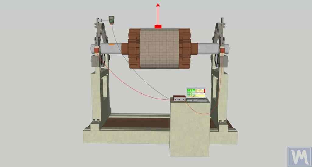
El centro de gravedad del rotor está desplazado del eje de rotación en un plano. Al colocarse sobre soportes de cuchilla, el lado pesado rueda hacia abajo: esto se puede detectar sin girar.
Corrección: agregar o retirar masa en una sola posición angular opuesta al punto pesado. Un solo plano de corrección es suficiente.
Aplica a: piezas estrechas en forma de disco donde el diámetro > 7× ancho: volantes, ruedas abrasivas, impulsores de disco único, hojas de sierra, discos de freno.
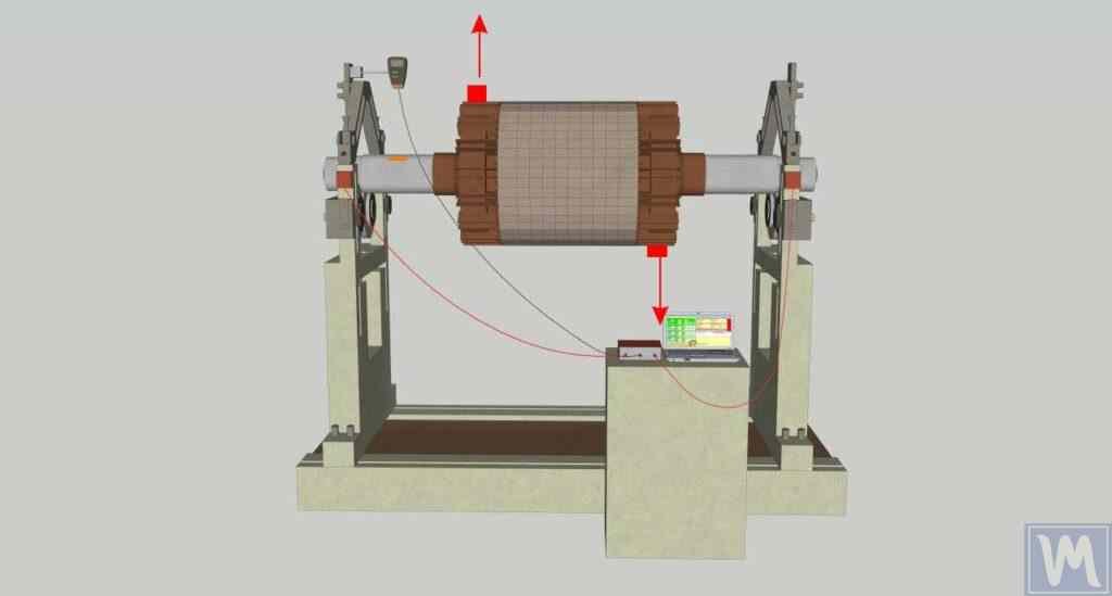
Dos (o más) desplazamientos de masa se encuentran en planos diferentes a lo largo del rotor. Pueden cancelarse entre sí estáticamente: el rotor permanece quieto sobre los soportes de cuchilla, pero generan un par de fuerzas oscilante al girar. Este par no puede detectarse ni corregirse sin rotación.
Corrección: dos pesos de compensación en dos planos separados. El instrumento calcula la masa y el ángulo para cada plano a partir de la matriz de coeficientes de influencia.
Aplica a: rotores alargados: ejes, ventiladores con impulsores anchos, rotores de mulcher, rodillos, impulsores de bombas multietapa, turbinas.
Cuatro tipos de desbalance
La norma ISO 21940-11 distingue cuatro patrones fundamentales de desbalance. Comprender cuál predomina ayuda a elegir la estrategia de balanceo correcta.
En la práctica, casi todos los rotores que se encuentran en campo tienen desbalance dinámico: una combinación de componentes de fuerza y par. Por eso, el balanceo en dos planos es el procedimiento predeterminado para cualquier rotor que no sea un disco delgado.
Cuándo usar balanceo de un plano vs. dos planos
El factor determinante es la relación geométrica L/D (longitud axial respecto al diámetro exterior) combinada con su velocidad de operación.
| Criterio | Un plano (1 sensor) | Dos planos (2 sensores) |
|---|---|---|
| Relación L/D | L/D < 0.14 (diámetro > 7× ancho) | L/D ≥ 0.14 |
| Piezas típicas | Rueda abrasiva, volante, impulsor de disco único, polea, disco de freno, hoja de sierra | Rotor de ventilador, trituradora, eje, rodillo, bomba multietapa, turbina, trituradora |
| Tipos de desbalance corregidos | Solo estático (fuerza) | Estático + par + dinámico (fuerza + momento) |
| Planos de corrección | 1 | 2 |
| Ejecuciones de medición | 2 (inicial + 1 prueba) | 3 (inicial + 2 pruebas, una por plano) |
| Tiempo en sitio | 15–20 min | 30–45 min |
Grados de calidad de balanceo ISO 21940‑11
ISO 21940‑11 (el sucesor de ISO 1940‑1) asigna a cada clase de maquinaria rotativa un grado de calidad de balanceo G, definida como la velocidad máxima permisible del centro de gravedad del rotor en mm/s. El desbalance residual específico permisible eper (en g·mm/kg) se deriva de la clase y la velocidad de operación:
G — clase de calidad de balanceo (p. ej. 6.3 significa 6.3 mm/s)
ω — velocidad angular, rad/s
RPM — velocidad de operación, rev/min
| Grado | e·ω, mm/s | Tipos de máquina |
|---|---|---|
G 0.4 |
0.4 | Giroscopios, husillos de rectificadoras de precisión |
G 1.0 |
1.0 | Turboalimentadores, turbinas de gas, devanados de motores eléctricos pequeños con requisitos especiales |
G 2.5 |
2.5 | Motores eléctricos, generadores, turbinas medianas/grandes, bombas con requisitos especiales |
G 6.3 |
6.3 | Ventiladores, bombas, maquinaria de proceso, volantes de inercia, centrífugas, maquinaria industrial general |
G 16 |
16 | Maquinaria agrícola, trituradoras, ejes de transmisión (cardán), partes de máquinas trituradoras |
G 40 |
40 | Ruedas de automóviles de pasajeros, conjuntos de cigüeñales (producción en serie) |
G 100 |
100 | Conjuntos de cigüeñales de motores diésel marinos grandes y de baja velocidad |
Ejemplo resuelto: Rotor de ventilador
Un rotor de ventilador centrífugo pesa 80 kg, opera a 1,450 RPM y el radio de corrección es de 250 mm. Clase requerida: G 6.3.
Con radio de corrección de 250 mm: masa residual máxima = 3320 / 250 = 13.3 g por plano
Esto significa que cada plano de corrección puede retener no más de 13.3 g de desbalance — aproximadamente el peso de tres arandelas M6.
Normas relacionadas: ISO 21940‑11 (rotores rígidos), ISO 21940‑12 (rotores flexibles), ISO 10816‑3 (límites de severidad de vibración), ISO 1940 (predecesora obsoleta).
Procedimiento de balanceo en campo en siete pasos
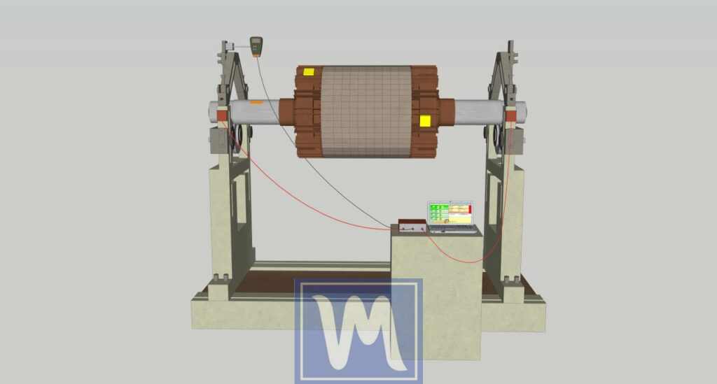
Este es el método de coeficientes de influencia para el balanceo en campo en dos planos, aplicado con un instrumento portátil como el Balanset‑1A. La misma lógica funciona con cualquier analizador de balanceo de dos canales.

Mt = Mr × K / (Rt × (N/100)²) donde Mr = masa del rotor (g), K = coeficiente de rigidez del soporte (1–5, use 3 para promedio), Rt = radio de instalación (cm), N = RPM. O use nuestra calculadora de peso de prueba en línea — ingrese los parámetros de su rotor y obtenga la masa recomendada al instante.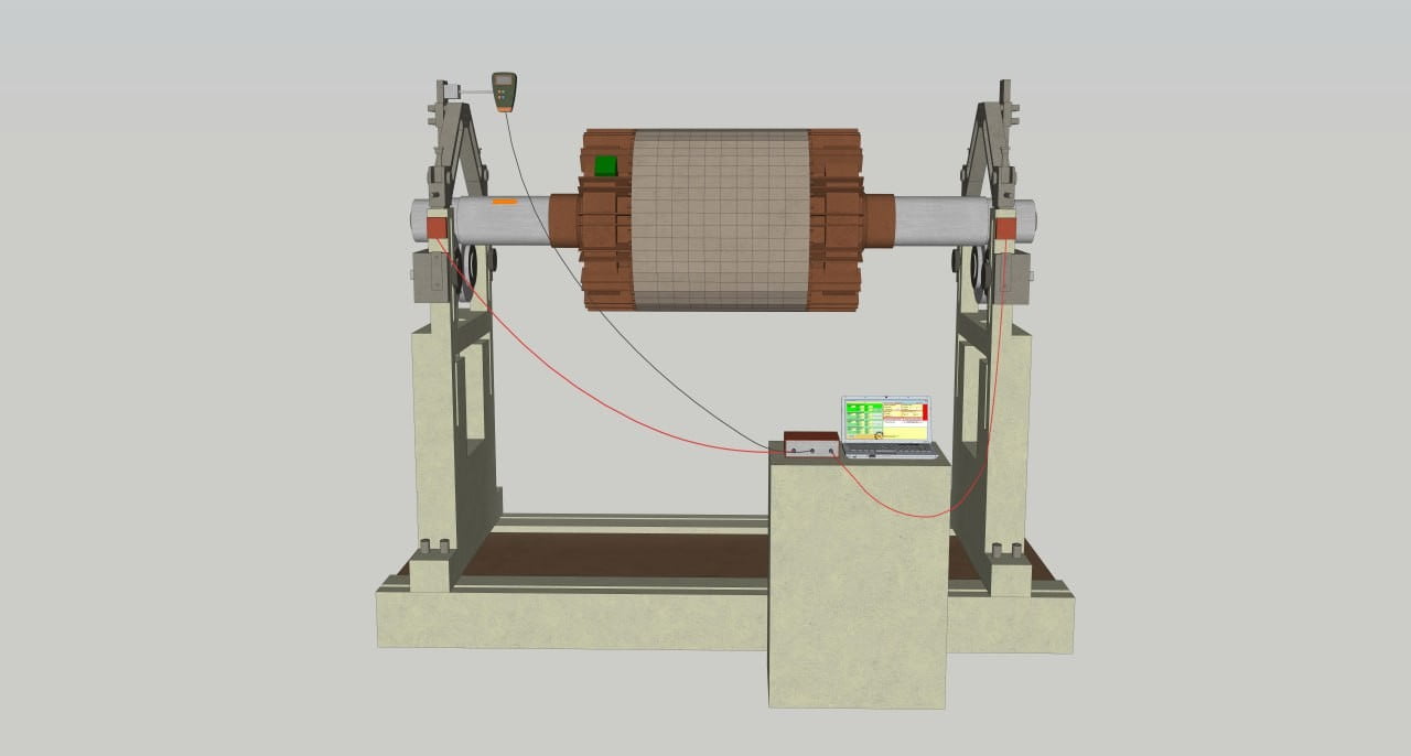

Cálculo del peso de prueba
El peso de prueba debe ser lo suficientemente pesado para producir un cambio de vibración notable, pero lo suficientemente ligero para no sobrecargar los rodamientos ni crear una condición peligrosa. La fórmula empírica estándar tiene en cuenta la masa del rotor, el radio de corrección, la velocidad de funcionamiento y la rigidez del soporte:
Mr — masa del rotor, gramos
K — coeficiente de rigidez del soporte (1 = soportes blandos, 3 = promedio, 5 = cimentación rígida)
Rt — radio de instalación del peso de prueba, cm
N — velocidad de funcionamiento, RPM
¿No quiere hacer las matemáticas a mano? Use nuestra calculadora de peso de prueba en línea ↗ — ingrese los parámetros de su rotor, el tipo de soporte y el nivel de vibración, y obtenga la masa recomendada al instante.
Ejemplos prácticos (K = 3, rigidez promedio)
| Máquina | Masa del rotor | RPM | Radio | Peso de prueba (K = 3) |
|---|---|---|---|---|
| Rotor de moldeadora | 120 kg | 2,200 | 30 cm | 360,000 / (30 × 484) ≈ 25 g |
| Ventilador industrial | 80 kg | 1,450 | 40 cm | 240,000 / (40 × 210.25) ≈ 29 g |
| Tambor de centrífuga | 45 kg | 3,000 | 15 cm | 135,000 / (15 × 900) = 10 g |
| Eje de trituradora | 250 kg | 900 | 25 cm | 750,000 / (25 × 81) ≈ 370 g |
Medición del ángulo de corrección
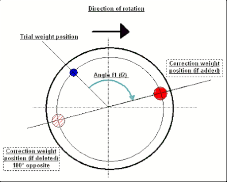
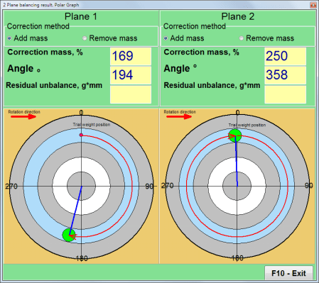
El instrumento de balanceo proporciona dos números por plano: masa (cuánto peso) y ángulo (dónde colocarlo). El ángulo siempre se referencia a la posición del peso de prueba.
Cómo medir el ángulo
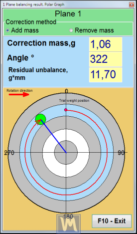
- Punto de referencia (0°): la posición angular donde colocó el peso de prueba. Márquela claramente en el rotor antes de la prueba.
- Dirección de medición: siempre en la dirección de rotación del rotor.
- Lectura del ángulo: el instrumento muestra el ángulo f₁ para el Plano 1 y f₂ para el Plano 2. Desde la marca del peso de prueba, cuente esos grados en la dirección de rotación; ahí es donde va el peso de corrección.
- Si se debe retirar masa: coloque la corrección a 180° opuesto a la posición indicada de "agregar".
División del peso en posiciones fijas
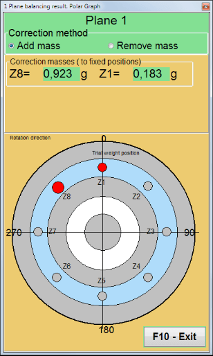
Cuando el rotor tiene agujeros preperforados o posiciones de montaje fijas (p. ej., pernos de aspas de ventilador), es posible que no pueda colocar un peso en el ángulo exacto calculado. El Balanset‑1A incluye una función de división de peso: ingresa los ángulos de las dos posiciones disponibles más cercanas, y el software descompone el vector de corrección único en dos pesos menores en esas posiciones. El efecto combinado coincide con el vector original.
Planos de corrección y colocación de sensores
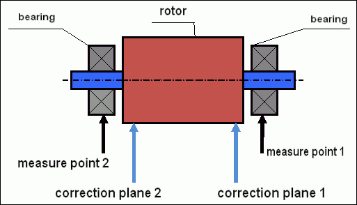
El plano de corrección es la posición axial en el rotor donde se agrega o retira masa. El sensor mide la vibración en el rodamiento más cercano. Algunas reglas clave:
- El sensor se coloca en el soporte del rodamiento — lo más cerca posible de la línea central del rodamiento, en dirección radial (horizontal preferible).
- El plano 1 corresponde al sensor 1, el plano 2 al sensor 2. Mantenga la numeración consistente o el software intercambiará los planos de corrección.
- Maximice la separación de planos: cuanto más separados estén los dos planos de corrección, mejor será la resolución del par. La separación práctica mínima es ⅓ de la distancia entre rodamientos.
- Elija posiciones accesibles: el plano de corrección debe ser una ubicación donde pueda fijar físicamente los pesos: el borde de una brida, un círculo de pernos, un aro o una superficie de soldadura.
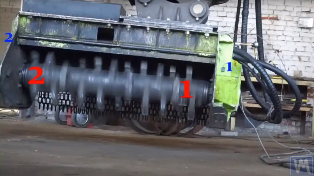
En la foto anterior, un rotor de mulcher está preparado para balanceo en dos planos. Las marcas azules 1 y 2 indican las posiciones de los sensores en los soportes de los rodamientos. Las marcas rojas 1 y 2 muestran los planos de corrección: en este caso, los extremos con brida del cuerpo del rotor donde se soldarán los pesos.
Rotor en voladizo (sobresaliente)
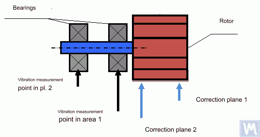
Los rotores en voladizo: impulsores de ventiladores, volantes montados fuera del tramo de rodamientos, impulsores de bombas, requieren un diseño diferente de sensores y planos. Ambos planos de corrección están del mismo lado de los rodamientos, y la colocación de los sensores debe tener en cuenta que la masa en voladizo amplifica el desbalance de par.
Aplicaciones por tipo de máquina
Métodos de fijación de pesos
| Método | Fijación | Ideal para | Límites |
|---|---|---|---|
| Soldadura | Arandelas o placas de acero soldadas por puntos al borde del rotor | Trituradoras de discos, trituradoras, rotores industriales pesados | Permanente. No se puede usar en aluminio o acero inoxidable sin electrodo especial |
| Pernos y tuercas | Pernos a través de agujeros preperforados con tuercas de seguridad | Impulsores de ventiladores, volantes, bridas de acoplamiento | Requiere agujeros existentes o nueva perforación |
| Abrazaderas de manguera | Abrazadera de manguera de acero inoxidable con peso intercalado | Ejes, rodillos, rotores cilíndricos en campo | Temporal o semipermanente. Verifique el par de apriete de la abrazadera |
| Clip con tornillo de presión | Pesos de clip prefabricados (como los de llantas) | Aspas de ventilador, bordes delgados, rotores ligeros | Rango de masa limitado. Puede deslizarse a altas RPM |
| Adhesivo (epoxi) | Peso pegado a la superficie | Rotores de precisión, entornos limpios | Requiere superficie limpia y seca. Límite de temperatura ~120°C |
| Retiro de material | Perforación o rectificado para retirar material del lado pesado | Turboalimentadores, husillos de alta velocidad, impulsores | Permanente y preciso, pero irreversible. Usar cuando añadir peso no sea seguro |
Errores comunes en el balanceo en campo
| # | Error | Consecuencia | Solución |
|---|---|---|---|
| 1 | Sensor montado en una protección o cubierta | La resonancia de la cubierta distorsiona las lecturas de amplitud y fase → corrección incorrecta | Montar siempre sobre la superficie metálica del soporte del rodamiento |
| 2 | Peso de prueba demasiado ligero | El cambio de fase y amplitud está dentro del ruido → los coeficientes de influencia son poco confiables | Asegurar un cambio de amplitud ≥30% o un desplazamiento de fase ≥30° en al menos un sensor |
| 3 | Variación de velocidad entre mediciones | La vibración a 1× cambia con RPM² — incluso un cambio de velocidad del 5% corrompe los datos | Usar un tacómetro para un seguimiento preciso de las RPM. Esperar a que la velocidad se estabilice |
| 4 | Olvidar retirar el peso de prueba | El cálculo de corrección incluye el efecto del peso de prueba → el resultado carece de sentido | Seguir una rutina estricta: retirar el peso de prueba antes de instalar los pesos de corrección |
| 5 | Confundir el Plano 1 y el Plano 2 | Los pesos de corrección se colocan en los planos incorrectos → la vibración aumenta | Etiquetar claramente los sensores y los planos. Sensor 1 → Plano 1, Sensor 2 → Plano 2 |
| 6 | Medir el ángulo en sentido opuesto a la rotación | La corrección se aplica a 360° − f en lugar de f → lado opuesto del rotor | Confirmar la dirección de rotación antes de comenzar. Medir siempre en la dirección de rotación |
| 7 | Dilatación térmica durante las mediciones | El juego del rodamiento cambia entre las mediciones en frío → mediciones erráticas | Calentar hasta alcanzar el estado estable antes de la medición 0, o completar todas las mediciones rápidamente (<5 min de diferencia) |
| 8 | Usar balanceo en un solo plano en un rotor largo | El desbalance de par queda sin corregir → la vibración puede incluso aumentar en el rodamiento lejano | Usar balanceo en dos planos para cualquier rotor donde L/D ≥ 0.14 o la separación entre planos sea significativa |
Informe de campo: Balanceo de rotor de trituradora de molienda
Máquina: Desmulsor de martillos Maschio Bisonte 280, rotor de 165 kg, velocidad de TMA de 2,100 RPM. El cliente reportó vibración severa después de reemplazar 8 martillos.
Configuración: Dos acelerómetros en los soportes de los rodamientos, tacómetro láser en el eje de la TMA. Modo de dos planos del Balanset-1A.
Serie 0: Sensor 1 = 12.4 mm/s @ 47°, Sensor 2 = 8.9 mm/s @ 213°. Zona D (peligro) de la norma ISO 10816-3.
Pruebas de giro: Se utilizó un peso de prueba de 500 g en ambos planos. Respuesta clara: cambio de amplitud >60% en ambos sensores.
Corrección: Plano 1: 340 g soldados a 128°. Plano 2: 215 g soldados a 276°.
Verificación: Sensor 1 = 0.8 mm/s, Sensor 2 = 0.6 mm/s. Zona A (buena) de la norma ISO. No se requirió prueba de ajuste.
Balanceo dinámico en dos planos de un ventilador
Los ventiladores industriales — centrífugos, axiales y de flujo mixto — están entre los rotores más comunes que se balancean en campo. El procedimiento a continuación describe un trabajo real de dos planos en un ventilador radial utilizando el Balanset-1A.
Determinación de planos e instalación de sensores
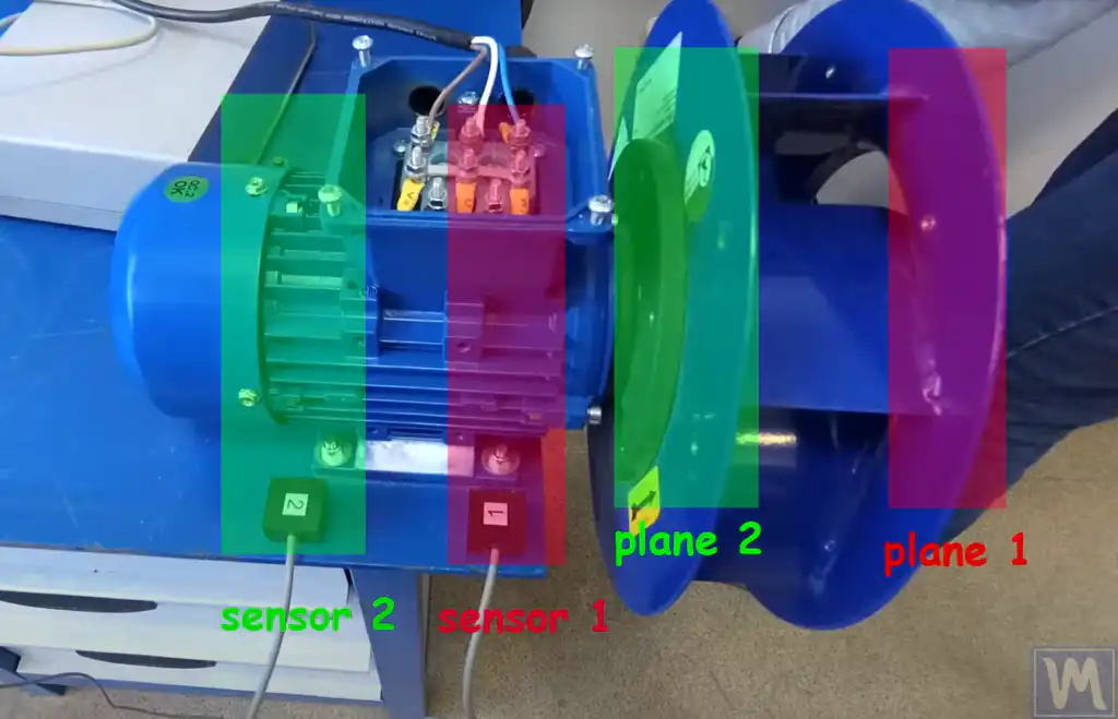
Limpie las superficies para la instalación de los sensores de suciedad y aceite. Los sensores deben ajustarse firmemente a la superficie metálica del soporte del rodamiento; nunca los monte en tapas, protecciones o paneles de chapa sin soporte.
- Sensor 1 (rojo): Instálelo más cerca del frente del ventilador (lado del Plano 1).
- Sensor 2 (verde): Instálelo más cerca de la parte trasera del ventilador (lado del Plano 2).
- Plano 1 (zona roja): Plano de corrección en el disco del impulsor, más cerca del frente.
- Plano 2 (zona verde): Plano de corrección más cerca de la placa trasera o del buje.
Conecte ambos sensores de vibración y el tacómetro láser al Balanset-1A. Fije cinta reflectante al eje o al buje para la referencia de RPM.
Proceso de balanceo
Inicie el ventilador y tome las mediciones iniciales de vibración (Giro 0). Instale un peso de prueba de masa conocida en el Plano 1 en un punto arbitrario, haga funcionar el ventilador y registre el cambio de vibración (Giro 1). Mueva el peso de prueba al Plano 2 en un punto arbitrario, haga funcionar el ventilador nuevamente y registre (Giro 2). El software del Balanset-1A utiliza las tres mediciones para calcular la masa y el ángulo de corrección para cada plano.
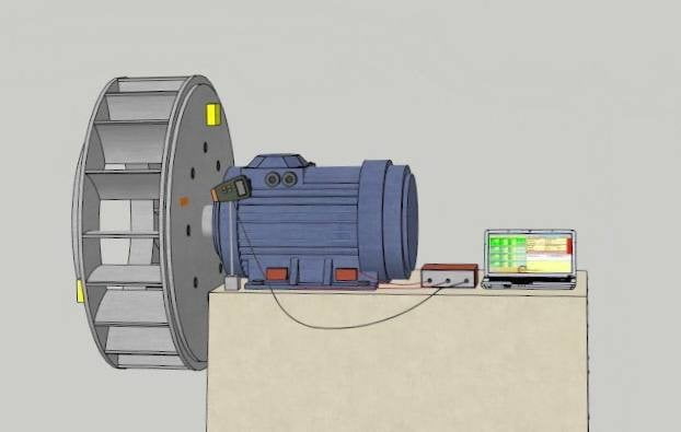
Medición del ángulo para los pesos de corrección del ventilador
El ángulo se mide desde la posición del peso de prueba en la dirección de rotación del ventilador, exactamente como se describe en la Medición del ángulo de corrección sección anterior. Marque dónde se colocó el peso de prueba (referencia de 0°), luego cuente el ángulo indicado en la dirección de rotación para encontrar la posición del peso de corrección.

Basado en los ángulos y masas calculados por el software, instale los pesos de corrección en el Plano 1 y el Plano 2. Haga funcionar el ventilador una vez más y verifique que la vibración haya disminuido a un nivel aceptable según ISO 21940‑11 (típicamente G 6.3 para ventiladores de propósito general). Si la vibración residual sigue por encima del objetivo, realice una prueba de ajuste.
Preguntas frecuentes
Equipo para balanceo en campo
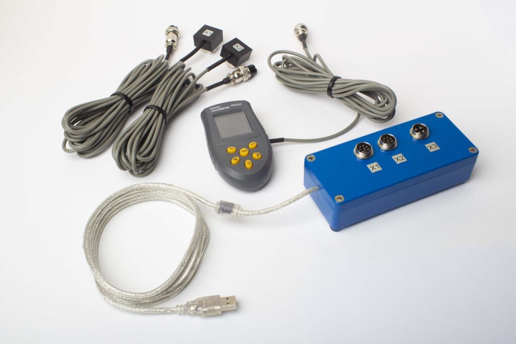
Balanset‑1A es un instrumento portátil de dos canales que realiza balanceo dinámico en un plano y en dos planos, además de análisis de vibración (velocidad global, espectros, forma de onda). Se entrega como un kit completo:
- 2× sensores de vibración piezoeléctricos con soportes magnéticos
- Tacómetro láser (sensor de RPM sin contacto) con cinta reflectante
- Unidad de medición USB (se conecta a cualquier laptop con Windows)
- Software: asistente de balanceo, medidor de vibración, analizador de espectros
- Maletín de transporte con todos los cables y accesorios
Rango de medición de velocidad de rotación: 250–90,000 rpm. Rango de medición de velocidad de vibración RMS (vibración 1×): 0.2–80 mm/s. Precisión de fase: ±1°. División de pesos, corridas de ajuste, verificación de tolerancias y generación de informes incluidos en el software. La masa del kit completo es menor a 5 kg. Vea el manual de operación, sección 2, para especificaciones.

Nikolai Shelkovenko
Nikolai Shelkovenko es ingeniero en análisis de vibraciones y fundador y director general de Vibromera. Desde hace más de 15 años balancea equipos rotativos en campo y no en un banco de pruebas: desbrozadoras, ventiladores industriales, trituradoras, centrífugas, ejes y husillos. De ese trabajo nacieron los instrumentos Balanset — se concibieron como una herramienta que el especialista puede llevar hasta la máquina y usar solo, en sitio, y no como equipo de laboratorio. Vibromera se fundó en 2017 y desde 2023 tiene su sede en Oporto, Portugal. Aquí se realizan el desarrollo, el ensamblaje y el soporte de la línea Balanset. El instrumento insignia es el Balanset-1A, un analizador portátil para el balanceo en uno y dos planos y para el diagnóstico de vibraciones. Nikolai participa personalmente en la atención al cliente, en la resolución de casos difíciles de balanceo y en el desarrollo del software. Trabaja con clientes de todo el mundo, en cualquier idioma.


0 comentario