बॅलन्सिंग सेवा › दोन-प्लेन (डायनॅमिक) बॅलन्सिंग
दोन-प्लेन (डायनॅमिक) बॅलन्सिंग — पद्धत, भौतिकशास्त्र आणि फील्ड प्रक्रिया
रोटर इतका रुंद असेल की प्रत्येक टोकावरील असंतुलन वेगळे असेल, तर एकच करेक्शन प्लेन पुरेसे नसते. दोन-प्लेन डायनॅमिक बॅलन्सिंग स्थिर आणि कपल हे दोन्ही घटक एकाच वेळी दुरुस्त करते — इन्फ्लुएन्स-कोइफिशंट पद्धत — वापरून, त्यामुळे रोटर फक्त मध्यभागी नव्हे तर संपूर्ण लांबीवर सुरळीत धावतो.
थोडक्यात: रोटरमध्ये स्थिर असंतुलनाबरोबर कपल घटकही असेल — म्हणजे असंतुलन एका डिस्कमध्ये केंद्रित न होता शाफ्ट अक्षावर वितरित असेल — तेव्हा दोन-प्लेन (डायनॅमिक) बॅलन्सिंग आवश्यक असते. प्रत्येक बेअरिंग हाउसिंगवर एक कंपन सेन्सर आणि शाफ्टवर एक लेझर टॅकोमीटर वापरून, प्रत्येकी प्लेनमध्ये ठेवलेल्या ट्रायल वेट्सला रोटरचा प्रतिसाद मोजला जातो; त्यानंतर Balanset-1A दोन्ही प्लेन्ससाठी अचूक करेक्शन वस्तुमान आणि कोन एकाच वेळी सोडवते. मशीनमधून रोटर काढण्याची गरज नाही; बहुतांश रोटर्ससाठी संपूर्ण चार-रन प्रक्रिया कार्यरत वेगावर, रोटरच्या स्वतःच्या बेअरिंग्समध्ये, एका तासाच्या आत पूर्ण होते.
तुमच्या रोटरला दोन-प्लेन बॅलन्सिंगची गरज असल्याची चिन्हे
सिंगल-प्लेन करेक्शनमुळे एक बेअरिंग शांत होऊ शकते, पण दुसरे अजूनही हलत राहते. हे नमुने दिसल्यास, दोन-प्लेन उपचार हा योग्य उपाय आहे:
सिंगल-प्लेन विरुद्ध दोन-प्लेन: दोन प्लेन्सची गरज कधी पडते?
एक आणि दोन करेक्शन प्लेन्समधील निवड रोटरच्या भूमितीवर आणि त्याच्या असंतुलनाच्या स्वरूपावर अवलंबून असते. असंतुलनाचे तीन प्रकार समजून घेतले तर निर्णय लगेच करता येतो.
असंतुलनाचे तीन प्रकार
स्थिर असंतुलन — वस्तुमानकेंद्र फिरण्याच्या अक्षापासून बाजूला असते, पण मुख्य जडत्व-अक्ष त्याला समांतर असतो. एक करेक्शन प्लेन पुरेसे असते: जड बाजूला वस्तुमान वाढवा आणि रोटर बॅलन्स होतो. नेहमीचे रोटर्स: पातळ पुलीज, अरुंद ग्राइंडिंग व्हील्स, सिंगल-प्लेन फॅन डिस्क्स.
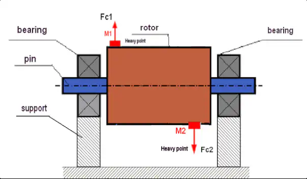
कपल असंतुलन — वस्तुमानकेंद्र अक्षावर असते, पण मुख्य जडत्व-अक्ष तिरपा असतो. रोटर डळमळतो, फक्त हलत नाही. हे एका प्लेनमध्ये दुरुस्त करता येत नाही; रॉकिंग मोमेंट रद्द करण्यासाठी दोन वेगळ्या प्लेन्समध्ये 180° अंतरावर सममात्र पण विरुद्ध दोन वस्तुमाने लागतात. नेहमीचे रोटर्स: लांब सिलिंड्रिकल ड्रम्स, मोटर आर्मेचर्स, शाफ्ट असेंब्लीज.
डायनॅमिक (संयुक्त) असंतुलन — सर्वसाधारण प्रकार: स्थिर आणि कपल हे दोन्ही घटक उपस्थित असतात. करेक्शनसाठी शाफ्टवर मनमानी निवडलेल्या दोन प्लेन्सची गरज असते. सर्व वास्तविक उत्पादन रोटर्स या श्रेणीत येतात.
| घटक | सिंगल-प्लेन (स्टॅटिक) | दोन-प्लेन (डायनॅमिक) |
|---|---|---|
| रोटरचा आकार | पातळ डिस्क; अक्षीय रुंदी व्यासापेक्षा खूप कमी | रुंद रोटर; अक्षीय रुंदी व्यासाइतकी किंवा त्याहून मोठी |
| असंतुलनाचा प्रकार | फक्त स्थिर असंतुलन | कपल किंवा संयुक्त (डायनॅमिक) असंतुलन |
| L/D गुणोत्तर (अक्षीय लांबी / व्यास) | L/D < 0.5 (अंदाजे) | L/D ≥ 0.5 (rigid rotor running below its first critical speed). Near or above a critical speed, evaluate the rotor as flexible first (ISO 21940-12) — two-plane balancing alone may be insufficient |
| सेन्सर्सची संख्या | 1 कंपन सेन्सर + 1 लेझर टॅको | 2 कंपन सेन्सर्स + 1 लेझर टॅको |
| मापन रनची संख्या | 3 रन (बेसलाइन + ट्रायल + करेक्शन) | 4 रन (बेसलाइन + प्लेन-1 ट्रायल + प्लेन-2 ट्रायल + करेक्शन) |
| सुधार समतल | 1 | 2 |
| नेहमीची उपकरणे | अरुंद फॅन इम्पेलर्स, पुलीज, सिंगल-स्टेज डिस्क्स | ड्रम्स, ड्राइव्हशाफ्ट्स, रुंद इम्पेलर्स, मल्टी-स्टेज रोटर्स, मोटर रोटर्स |
| मानक संदर्भ | ISO 21940-11 (1-प्लेन रिगिड रोटर) | ISO 21940-11 (2-प्लेन रिगिड रोटर) |
ढोबळ नियम: जर एका बेअरिंगवर मोजलेले रोटरचे कंपन ट्रायल वेट हलवल्यावर दुसऱ्या बेअरिंगवरील कंपनाच्या विरुद्ध दिशेने बदलत असेल, तर कपल घटक उपस्थित आहे आणि दोन प्लेन्स आवश्यक आहेत.
रुंद रोटर्सचे डायनॅमिक संतुलन का बिघडते — आणि त्याची किंमत काय
रोटर तयार केला जातो किंवा दुरुस्त केला जातो तेव्हा वस्तुमान क्वचितच त्याच्या अक्षावर सममितीने वितरित केलेले असते. इरोशन इम्पेलरच्या एका टोकाला दुसऱ्यापेक्षा जलद कुरतडते; वेल्ड दुरुस्त्या एका अक्षीय स्थानावर पदार्थ वाढवतात; उत्पादन साठा ड्रमवर असमानपणे जमा होतो. परिणामी केवळ स्थिर असंतुलनच नाही तर कपल घटक तयार होतो, जो रॉकिंग मोमेंट निर्माण करतो. दोन्ही फक्त दोन प्लेन्समधील एकाचवेळी करेक्शननेच दूर होतात. कारण केंद्रापसारक बल वर्गाच्या प्रमाणात घूर्णन वेगाच्या वर्गानुसार वाढते, त्यामुळे 500 RPM वरील मामुली कपल असंतुलन 3,000 RPM वर विध्वंसक बलात बदलते.
कपल घटकाकडे दुर्लक्ष केल्यास दोन्ही बेअरिंग्सवर प्रत्येक फेरीला वाढलेले डायनॅमिक भार येतात. बेअरिंग थकवा वाढतो, सील्स निकामी होतात, फास्टनर्स सैल होतात, आणि संरचनात्मक तडे माउंटिंग फूट्सपासून बाहेर पसरतात. आर्थिक नुकसान — बेअरिंग्स, सील्स, उत्पादनातील तोटा, आपत्कालीन मजुरी — हे योग्य दोन-प्लेन कामाच्या खर्चापेक्षा अनेक पटींनी जास्त असते.
व्हायब्रेशन अर्धे केल्याने बेअरिंगचे आयुष्य अनेकपट का वाढते
दोन-प्लेन बॅलन्सिंग — चरण-दर-चरण फील्ड प्रक्रिया
Balanset-1A इन्फ्लुएन्स-कोइफिशंट पद्धत लागू करते. दोन कंपन सेन्सर्स आणि एक लेझर टॅको रोटरचे पूर्ण वर्णन करतात आणि एका ऑन-साइट सत्रात दोन्ही करेक्शन प्लेन्स सोडवतात:
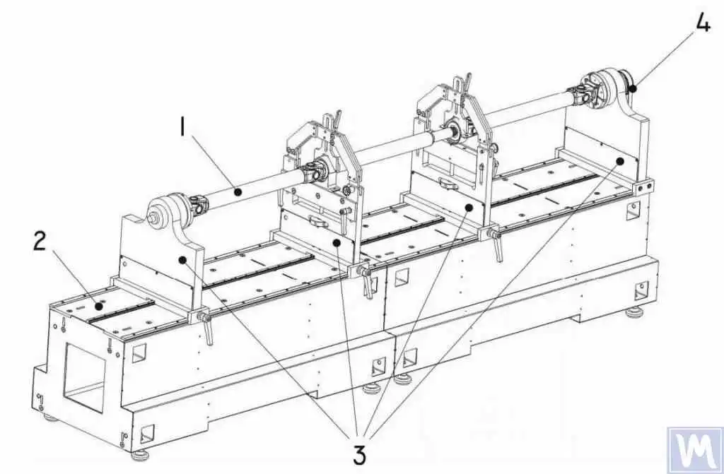
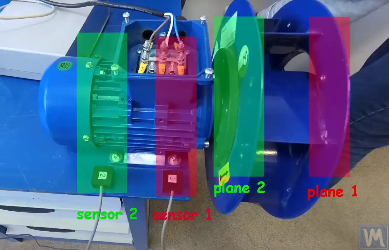
- सेंसर माउंट करा। प्रत्येक बेअरिंग हाउसिंगला (Planes 1 आणि 2) एक कंपन अॅक्सेलरोमीटर बसवा आणि लेझर टॅकोमीटर शाफ्टवरील परावर्तक पट्टीकडे लक्ष्यित करा. डिसअसेंब्लीची गरज नाही — संपूर्ण प्रक्रियेदरम्यान रोटर सामान्य कार्यस्थितीत चालतो.
- बेसलाइन मोजा. पूर्ण कार्यरत वेगावरील एक रन दोन्ही बेअरिंग स्थानांवरील कंपन अॅम्प्लिट्यूड आणि फेज कोन एकाच वेळी नोंदवते, ज्यामुळे दोन्ही प्लेन्समधील प्रारंभिक 1× RPM व्हेक्टर मिळतात आणि सुरुवातीची असंतुलन-स्थिती ठरते.
- प्लेन 1 मध्ये ट्रायल वेट जोडा. ज्ञात वस्तुमान पहिले करेक्शन प्लेनमध्ये चिन्हांकित कोनीय स्थितीवर क्लॅम्प केले जाते. दुसरी रन या वजनाचा कंपनावर होणारा परिणाम टिपते दोन्ही दोन्ही बेअरिंग स्थानांवर, ज्यामुळे चार इन्फ्लुएन्स कोइफिशंट्सपैकी दोन मिळतात.
- ट्रायल वेट प्लेन 2 मध्ये हलवा. तेच वस्तुमान दुसऱ्या करेक्शन प्लेनमध्ये पुन्हा बसवले जाते आणि दुसरी रन दोन्ही सेन्सर्सवरील क्रॉस-इन्फ्लुएन्स नोंदवते. आता उपकरणाकडे 2×2 प्रणालीसाठी आवश्यक सर्व चार इन्फ्लुएन्स कोइफिशंट्स असतात.
- उपकरणला गणना करू द्या. Balanset-1A दोन-प्लेन इन्फ्लुएन्स-कोइफिशंट समीकरणे सोडवते आणि प्रत्येक प्लेनसाठी अचूक करेक्शन वस्तुमान आणि कोनीय स्थिती एकाच वेळी दाखवते — मॅन्युअल अंकगणिताची गरज नाही.
- करेक्शन बसवा आणि पडताळा. गणना केलेल्या स्थानांवर दोन्ही प्लेन्समध्ये करेक्शन वेट्स बसवले जातात. अंतिम रन निर्दिष्ट G-ग्रेडसाठी अवशिष्ट असंतुलन ISO 21940-11 सहनशीलतेच्या मर्यादेत आहे याची पुष्टी करते, आणि Balanset-1A नोंदवलेला बॅलन्सिंग अहवाल जतन करते.
आम्ही दोन प्लेन्समध्ये जे बॅलन्स करतो
- रुंद सेंट्रिफ्यूगल फॅन इम्पेलर्स आणि डबल-इनलेट ब्लोअर्स
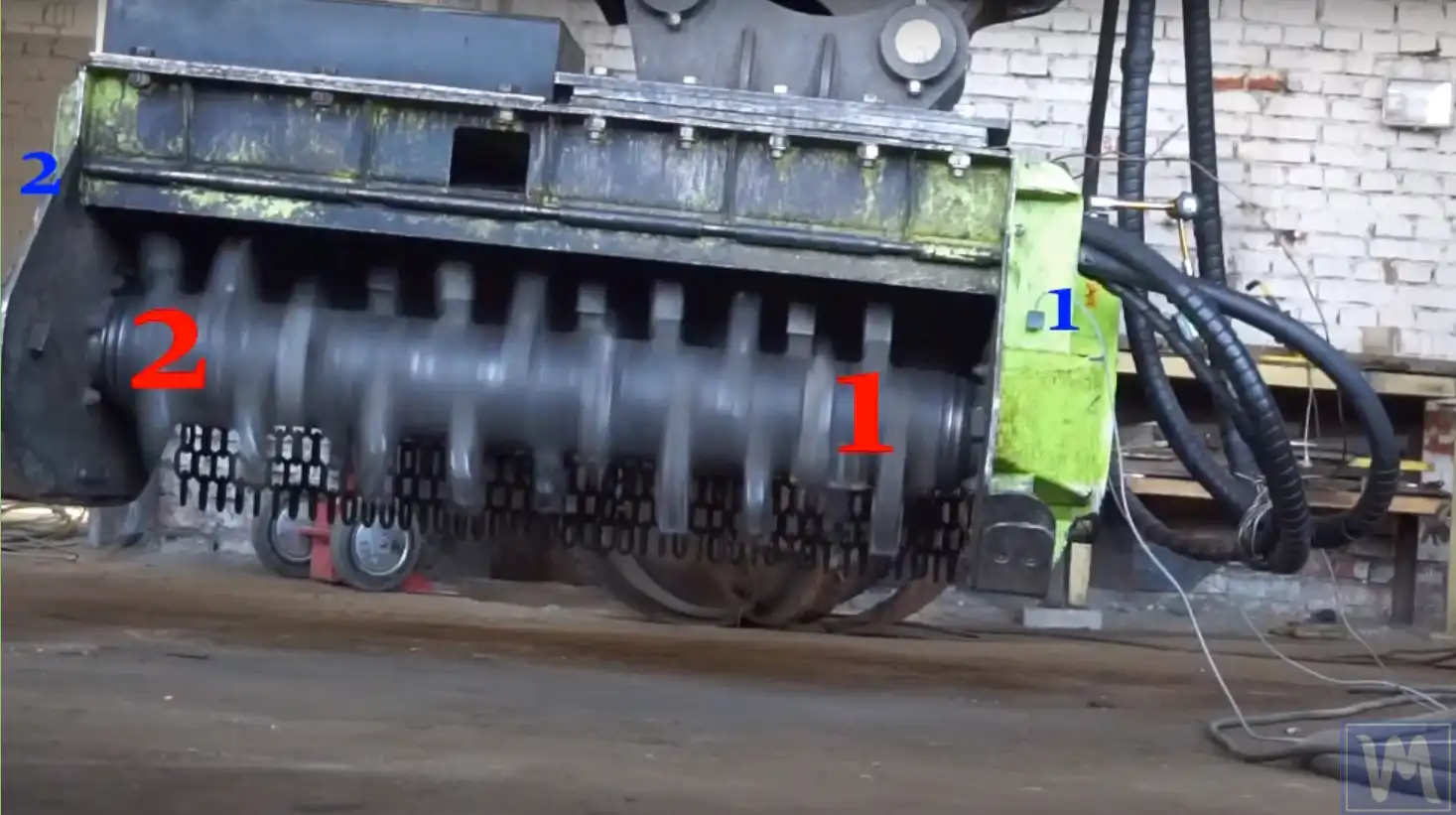
- कंबाईन-हार्वेस्टर थ्रेशिंग आणि चॉपिंग ड्रम्स
- ड्राइव शाफ्ट आणि कार्डान शाफ्ट
- मल्टी-स्टेज पंप रोटर्स आणि कंप्रेसर इम्पेलर स्टॅक्स
- पेपर-मशीन रोल्स आणि प्रिंटिंग / कोटिंग सिलिंडर्स
- ~500 mm पेक्षा लांब स्क्रू कन्व्हेयर्स आणि ऑगर्स
- लक्षणीय अक्षीय लांबी असलेले मोटर रोटर्स आणि जनरेटर रोटर्स
- टर्बोचार्जर रोटर्स आणि स्टीम-टर्बाइन रोटर्स (फील्ड कंपन पडताळणी)
- ज्या रोटरमध्ये सिंगल-प्लेन करेक्शननंतरही एक बेअरिंग हलत राहते असे कोणतेही रोटर
सहनशीलता & मानक
ISO 21940-11 (formerly ISO 1940-1) defines balance quality grades G0.4 through G4000 for rigid rotors. For rigid rotors — those operating well below their first critical speed — an axial-length-to-diameter ratio above roughly 0.5 usually calls for two-plane balancing. A rotor that operates near or above a critical speed must first be evaluated as a flexible rotor per ISO 21940-12: it may need balancing at several speeds and in more than two planes, so ordinary two-plane rigid-rotor balancing can be insufficient. The permissible residual unbalance per plane is calculated as:
Uनुसार (g·mm) = eनुसार × m / 2, जिथे eनुसार = G × 9549 / n (mm/s × rpm → μm eccentricity), m is the rotor mass in kg, and the factor 2 splits the tolerance equally between the two planes. Note that the equal split is a practical approximation for roughly symmetric rotors with correction planes near the bearings — not a universal ISO allocation rule; ISO 21940-11 allocates the tolerance differently for asymmetric plane and bearing arrangements.
फॅन रोटर्स सामान्यतः यापर्यंत बॅलन्स केले जातात G6.3 or G2.5 नुसार ISO 14694; प्रिसिजन मशीन-टूल स्पिंडल्स आणि उच्च-वेग टर्बो उपकरणे G1.0 किंवा त्याहून सूक्ष्म ग्रेड लक्ष्य करतात. आमचा वापरा अवशिष्ट-असंतुलन कॅल्क्युलेटर काम सुरू करण्यापूर्वी तुमच्या G-ग्रेड, रोटर वस्तुमान आणि सेवा वेगासाठी अनुमत सहनशीलता शोधण्यासाठी.
Balanset-1A — आपल्या संपूर्ण फील्ड-संतुलन किट
कोणत्याही कडक रोटरचे दोन-प्लेन डायनॅमिक बॅलन्सिंग — फॅन्स, ड्रम्स, ड्राइव्हशाफ्ट्स, मल्टी-स्टेज पंप असेंब्लीज — एका पोर्टेबल उपकरणाने केले जाते: the Balanset-1A. हे दोन-चॅनेल डायनॅमिक बॅलन्सर आणि कंपन विश्लेषक आहे, जे रोटर्सचे बॅलन्सिंग करते त्यांच्या स्वतःच्या बेअरिंगमध्ये, ऑपरेटिंग स्पीडवर, इन्फ्लुएन्स-कोइफिशंट पद्धत वापरून — एका प्लेनसाठी तीन रन, दोन प्लेन्ससाठी चार रन. सॉफ्टवेअर दोन्ही प्लेन्ससाठी अचूक करेक्शन वस्तुमान आणि कोन गणना करते आणि अहवाल जतन करते.
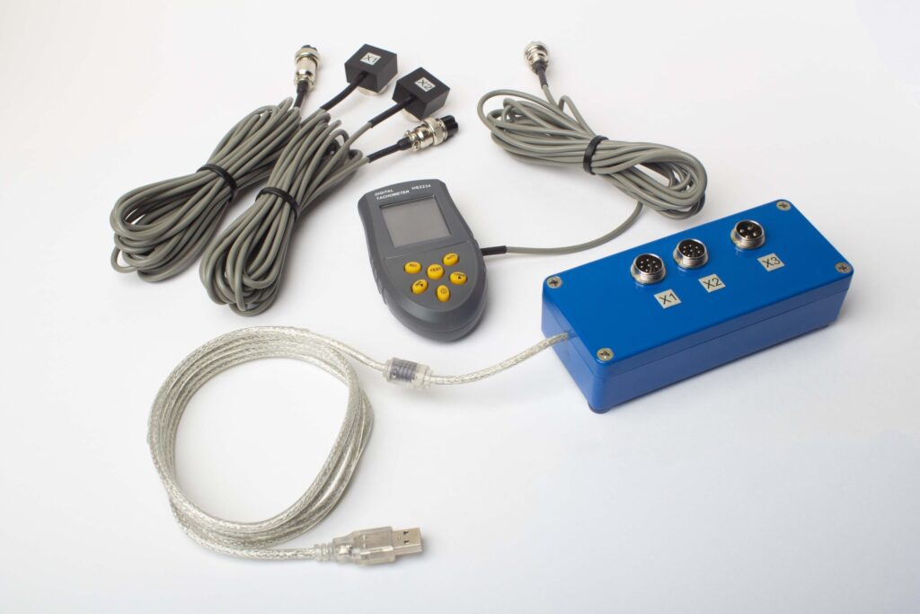
संपूर्ण किटमध्ये काय आहे
€1,975 · संपूर्ण किट, स्टॉकमध्ये, VAT इनव्हॉइस
- इंटरफेस मापन युनिट (USB, 2 चॅनल)
- दोन व्हायब्रेशन एक्सेलेरोमीटर (4 m केबल, 10 m पर्यायी)
- लेजर टॅकोमीटर / ऑप्टिकल फेज सेंसर (50–500 mm)
- सेंसरसाठी चुंबकीय स्टँड
- चाचणी & सुधारणा वजनसाठी डिजिटल स्केल
- Windows संतुलन & विश्लेषण सॉफ्टवेअर
- प्लास्टिक ट्रान्सपोर्ट केस
पूर्ण किट
युनिट · 2 सेन्सर्स · लेझर टॅकोमीटर · मॅग्नेटिक स्टँड · डिजिटल स्केल · सॉफ्टवेअर · ट्रान्सपोर्ट केस. बॉक्स उघडताच दोन-प्लेन बॅलन्सिंग सुरू करण्यासाठी लागणारे सर्व काही.
OEM संच
युनिट · 2 सेन्सर्स · लेझर टॅकोमीटर · सॉफ्टवेअर. ज्यांच्याकडे आधीच स्टँड, स्केल आणि केस आहे किंवा जे हे युनिट समर्पित बॅलन्सिंग मशीनमध्ये एम्बेड करतात अशा इंटिग्रेटर्ससाठी.
| परिमाण | मूल्य |
|---|---|
| मापन चॅनल | 2 (एक- & दोन-प्लेन संतुलन) |
| व्हायब्रेशन वेग रेंज | 0.2–80 mm/s RMS |
| वारंवारता श्रेणी | 5–1000 Hz (≤10% amplitude error above 550 Hz) |
| मापन अचूकता | ±5% पूर्ण स्केलचा |
| पद्धत | 3-धावा प्रभाव-गुणांक (1 किंवा 2 विमाने) |
| विश्लेषण | 1× वर मोठापणा & फेज, FFT स्पेक्ट्रम & तरंगरूप, संचयित अहवाल |
| लॅपटॉप | समाविष्ट नाही (Windows PC, विनंतीवर उपलब्ध) |
वास्तविक दोन-प्लेन बॅलन्सिंग प्रकरणे
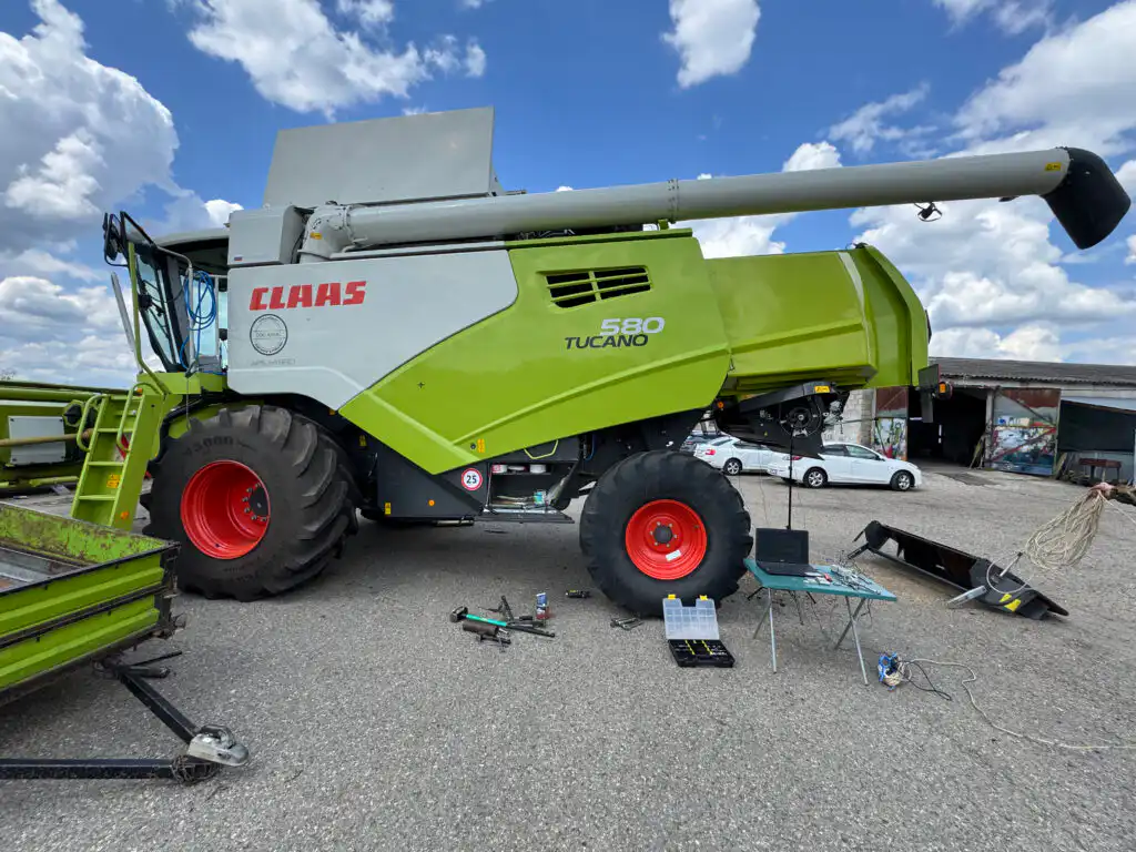
कंबाईन ड्रम (2-प्लेन)
कृषी कंबाईन हार्वेस्टरवर एका फील्ड सत्रात दोन्ही करेक्शन प्लेन्स बॅलन्स केले.
ड्राइव्हशाफ्ट (2-प्लेन)
लांब ड्राइव्हशाफ्टचे डायनॅमिक बॅलन्सिंग, प्रत्येक एंड फ्लॅंजवर करेक्शन वेट लावून.
रुंद एक्झॉस्टर इम्पेलर
जागेवर बॅलन्स केलेल्या रुंद औद्योगिक एक्झॉस्टर इम्पेलरवर दोन-प्लेन करेक्शन.
दोन-प्लेन बॅलन्सिंग — फील्डमधून
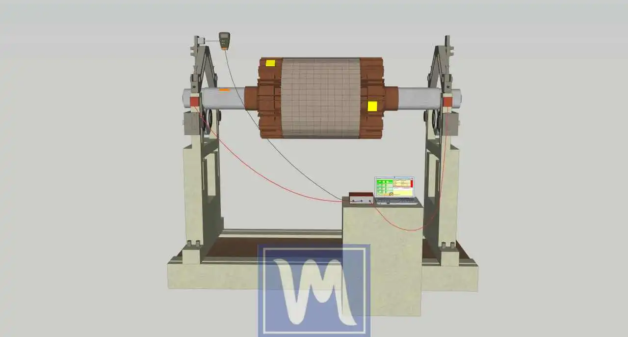
इन्फ्लुएन्स-कोइफिशंट सेटअप
दोन्ही करेक्शन प्लेन्सचे एकाच वेळी वर्णन करण्यासाठी दोन सेन्सर्स आणि एक लेझर टॅको योग्य स्थितीत ठेवलेले.
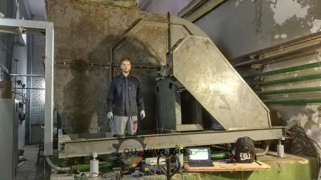
जागेवरच बॅलन्स केलेले
रोटर स्वतःच्या बेअरिंग्समध्येच राहतो आणि कार्यरत वेगावर दुरुस्त केला जातो — काढण्याची गरज नाही.
दोन्ही प्लेन्स सोडवलेले
एका सत्रात प्लेन 1 आणि प्लेन 2 साठी करेक्शन वस्तुमान आणि कोन एकाच वेळी गणना केलेले.
पडताळलेला निकाल
अंतिम रन दोन्ही प्लेन्सवर ISO 21940-11 सहनशीलतेच्या मर्यादेत अवशिष्ट असंतुलन असल्याची पुष्टी करते.
दोन-प्लेन बॅलन्सिंगसाठी मोफत कॅलक्युलेटर्स
दोन-प्लेन बॅलन्सिंग FAQ
सिंगल-प्लेन बॅलन्सिंग कधी पुरेसे असते?
दोन प्लेन्ससाठी इन्फ्लुएन्स-कोइफिशंट पद्धत कशी काम करते?
दोन-प्लेन कामासाठी किती मापन रन लागतात?
मला रोटर मशीनमधून काढण्याची गरज आहे का?
माझ्या रोटरसाठी कोणता बॅलन्स-गुणवत्ता ग्रेड लक्ष्य करावा?
आमची देखभाल टीम Balanset-1A सह दोन-प्लेन बॅलन्सिंग करू शकते का?
सिद्धांत जाणून घ्या
दोन्ही प्लेन्स एका भेटीत सोडवा — कार्यरत वेगावर, काढणे न करता
Balanset-1A तुम्हाला पूर्ण दोन-प्लेन इन्फ्लुएन्स-कोइफिशंट प्रक्रियेतून नेते: बेसलाइन, प्लेन 1 ट्रायल, प्लेन 2 ट्रायल, करेक्शन आणि पडताळणी — हे सर्व चालू वेगावर, रोटरच्या स्वतःच्या बेअरिंग्समध्ये. ISO 21940-11, ISO 14694 आणि API 610 नुसार नोंदवलेले अवशिष्ट असंतुलन. शिपिंगसाठी तयार.
