Балансталау қызметтері › Екі жазықтықтағы (динамикалық) теңгеру
Екі жазықтықтағы (динамикалық) теңгеру — Әдіс, физика және далалық процедура
Ротор теңгерусіздік екі ұшында әртүрлі болатындай кең болған жағдайда, бір түзету жазықтығы жеткіліксіз. Екі жазықтықтағы динамикалық теңгеру статикалық және жұптық компоненттерді бір уақытта түзетеді — пайдалана отырып әсер коэффициенттері әдісі — сондықтан ротор тек ортасында ғана емес, толық ұзындығы бойынша тегіс жұмыс істейді.
In short: Екі жазықтықтағы (динамикалық) теңгеру ротор статикалық теңгерусіздікті де, жұптық компонентті де тасымалдайтын жағдайда талап етіледі — яғни теңгерусіздік бір дискіде шоғырланбай, білік осі бойынша таралған кезде. Әрбір подшипник тұрғысындағы дірілдеу датчигі және білікте лазерлі тахометр ротордың кезекпен әр жазықтыққа орналастырылған сынақ салмақтарына жауабын өлшеу үшін қолданылады; Balanset-1A екі жазықтықтағы дәл түзету массасы мен бұрышын бір уақытта есептейді. Машинадан алып шығу қажет емес — төрт жүрістен тұратын бүкіл процедура жұмыс жылдамдығында, ротордың өз подшипниктерінде, көптеген роторлар үшін бір сағаттан аз уақытта аяқталады.
Ротордың екі жазықтықтағы теңгеруді қажет ететін белгілері
Бір жазықтықтағы түзету бір подшипникті тынышталдырып, екіншісін дірілдетуі мүмкін. Егер осы үлгілердің кез келгенін байқасаңыз, екі жазықтықтағы теңгеру дұрыс шешім болып табылады:
Бір жазықтық пен екі жазықтықтың салыстырмасы: екі жазықтық қашан қажет?
Бір немесе екі түзету жазықтығы арасындағы таңдау ротор геометриясына және оның теңгерімсіздік сипатына байланысты. Үш теңгерімсіздік түрін түсіну шешімді дереу қабылдауға мүмкіндік береді.
Теңгерімсіздіктің үш түрі
Static unbalance — масса центрі айналу осінен ауытқыған, бірақ негізгі инерция осі соған параллель. Бір түзету жазықтығы жеткілікті: ауыр жаққа масса қосу арқылы ротор теңгеріледі. Типтік роторлар: жіңішке шкивтер, тар тегістеу дөңгелектері, бір жазықтықты желдеткіш дискілері.
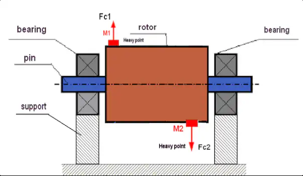
Жұптық дисбалансы — масса центрі осінде орналасқан, бірақ негізгі инерция осі еңкейген. Ротор шайқалады, дірілдемейді. Бұл бір жазықтықта түзетуге болмайды; тербеліс моментін жою үшін екі бөлек жазықтықта 180° қарама-қарсы орналасқан тең екі масса қажет. Типтік роторлар: ұзын цилиндрлік барабандар, электр қозғалтқыштарының якорьлары, білік жиынтықтары.
Динамикалық (аралас) теңгерімсіздік — жалпы жағдай: статикалық және момент-теңгерімсіздіктің екі компоненті де болады. Түзету білік бойынша еркін таңдалған екі жазықтықта жасалуы тиіс. Нақты өндірістік роторлардың барлығы осы санатқа жатады.
| Factor | Бір жазықтықта (статикалық) | Екі жазықтықта (динамикалық) |
|---|---|---|
| Rotor shape | Жіңішке диск; осьтік ені диаметрінен әлдеқайда аз | Кең ротор; осьтік ені диаметрімен шамалас немесе одан үлкен |
| Unbalance type | Тек статикалық дисбаланс | Момент немесе бірлескен (динамикалық) дисбаланс |
| L/D қатынасы (осьтік ұзындық / диаметр) | L/D < 0.5 (шамамен) | L/D ≥ 0.5 (rigid rotor running below its first critical speed). Near or above a critical speed, evaluate the rotor as flexible first (ISO 21940-12) — two-plane balancing alone may be insufficient |
| Датчиктер саны | 1 тербеліс датчигі + 1 лазерлік тахометр | 2 тербеліс датчигі + 1 лазерлік тахометр |
| Өлшеу жүрістерінің саны | 3 жүріс (бастапқы + пробалық салмақ + түзету) | 4 жүріс (бастапқы + 1-жазықтықтың пробалық салмағы + 2-жазықтықтың пробалық салмағы + түзету) |
| Түзету ұшақтары | 1 | 2 |
| Жабдықтың типтік мысалдары | Тар желдеткіш жетектері, шкивтер, бір сатылы дискілер | Барабандар, карданды біліктер, кең жетектер, көп сатылы роторлар, электрқозғалтқыш роторлары |
| Стандартты анықтама | ISO 21940-11 (бір жазықтықтағы қатты ротор) | ISO 21940-11 (екі жазықтықтағы қатты ротор) |
Rule of thumb: егер сынақ салмағын жылжытқанда бір мойынтіректегі өлшенген ротор діріліне қарама-қарсы бағытта екінші мойынтіректегі дірілдің өзгеруі байқалса, жұптық компонент бар деген сөз және екі түзету жазықтығы қажет.
Кең роторлар неліктен динамикалық балансын жоғалтады — және бұл қанша тұрады
Ротор дайындалған немесе жөнделген кезде масса оның осі бойымен сирек симметриялы түрде таралады. Эрозия тиектің бір ұшын екіншісінен жылдамырақ кемірді; дәнекерлеп жөндеу материалды жалғыз осьтік бекету нүктесіне қосады; өнім шөгінділері барабан бойымен біркелкі емес жиналады. Нәтижесінде тек статикалық теңгерімсіздік емес, сонымен қатар couple тербелме моментін тудыратын компонент пайда болады. Тек екі жазықтықта бір мезгілде түзету арқылы екеуін де жоюға болады. Орталықтан тепкіш күш айналу жылдамдығының square шамасымен өсетіндіктен, 500 RPM-дегі қалыпты жұптық теңгерімсіздік 3 000 RPM-де бұзушы күшке айналады.
Жұптық компонентті елемеу дегені — екі мойынтірек те әрбір айналым сайын жоғары динамикалық жүктемені көтереді. Мойынтірек шаршауы жинақталып, тығыздауыштар бұзылады, бекіткіштер бәсеңдейді, ал конструктивтік жарықтар тіреу табандарынан сыртқа қарай таралады. Экономикалық шығын — мойынтіректер, тығыздауыштар, жоғалған өнім, апаттық жөндеу жұмысы — әдетте дұрыс екі жазықтықта балансировкалау жұмысының өзіндік құнынан бірнеше есе артық болады.
Тербелісін екі есеге азайту неге подшипник өмірін ұлғайтады
Екі жазықтықта балансировкалау — орнында жүргізілетін қадамдық іс рәсімі
Balanset-1A әсер коэффициенттері әдісін қолданады. Екі тірілт сезгіші және бір лазерлік тахометр роторды толық сипаттайды және бір орындағы сеанста екі түзету жазықтығын да шешеді:
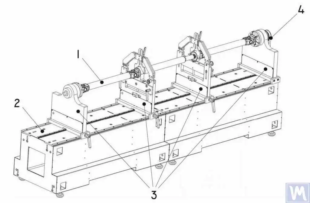
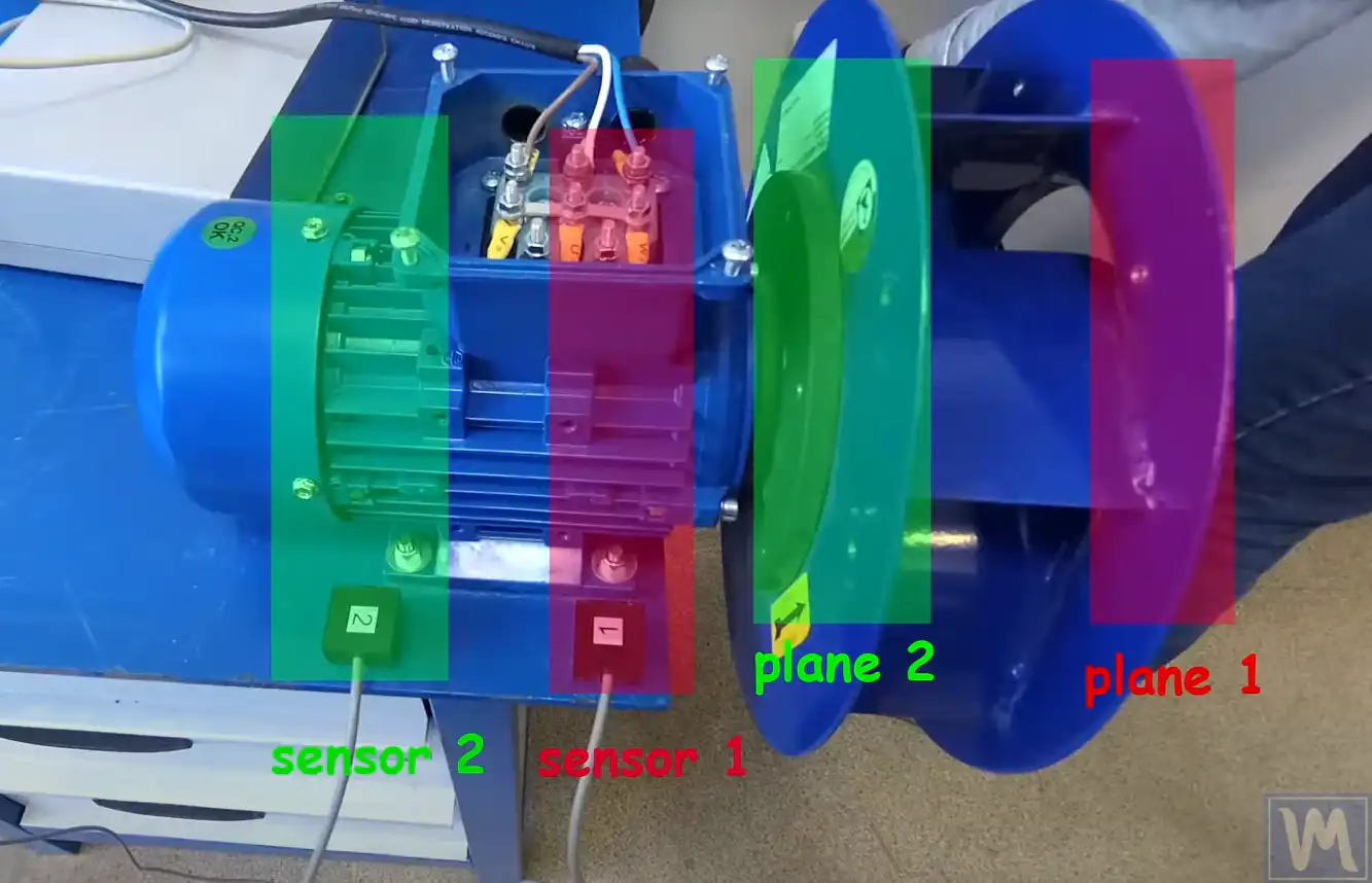
- Датчиктерді орнатыңыз. Дірілт акселерометрін әрбір мойынтірек корпусына (1 және 2 жазықтықтар) бекітіп, лазерлік тахометрді білікте жапсырылған шағылыстырғыш таспаға бағыттаңыз. Бөлшектеп-жинау қажет емес — ротор рәсім бойы қалыпты жұмыс жағдайында жұмыс істей береді.
- Бастапқы өлшеу жүргізіңіз. Толық жұмыс жылдамдығындағы бір іске қосу екі мойынтірек орнында дірілдің амплитудасы мен фаза бұрышын бір мезгілде жазады, бастапқы теңгерімсіздік күйін екі жазықтықта да анықтайтын 1× RPM векторларын береді.
- 1-жазықтыққа сынақ салмағын орнатыңыз. Белгілі масса бірінші түзету жазықтығындағы белгіленген бұрыштық орынға қысыммен бекітіледі. Екінші іске қосу бұл салмақтың дірілге қалай әсер ететінін жазады both мойынтірек орындарында, төрт әсер коэффициентінің екеуін береді.
- Сынақ салмағын 2-жазықтыққа жылжытыңыз. Сол масса екінші түзету жазықтығына ауыстырылады және тағы бір іске қосу екі сезгіштегі де айқасулы әсерді жазады. Енді құрылғының 2×2 жүйесі үшін қажетті төрт әсер коэффициентінің бәрі бар.
- Құрылғыға есептеуді орындат. Balanset-1A екі жазықтықтағы әсер коэффициенттері теңдеулерін шешіп, әрбір жазықтық үшін нақты түзету массасы мен бұрыштық орынды бір мезгілде шығарады — қолмен есептеу талап етілмейді.
- Түзетулерді орнатып, тексеріңіз. Түзету салмақтары есептелген орындарға екі жазықтықта да орналастырылады. Соңғы іске қосу қалдық теңгерімсіздіктің белгіленген G-сыныбы үшін ISO 21940-11 рұқсат нормасы шегінде екенін растайды, ал Balanset-1A балансировкалау туралы ресімделген есепті сақтайды.
Екі жазықтықта нені теңгерімдейміз
- Кең орталықтан тепкіш желдеткіш қанатшалары және қос кірісті үрлегіштер
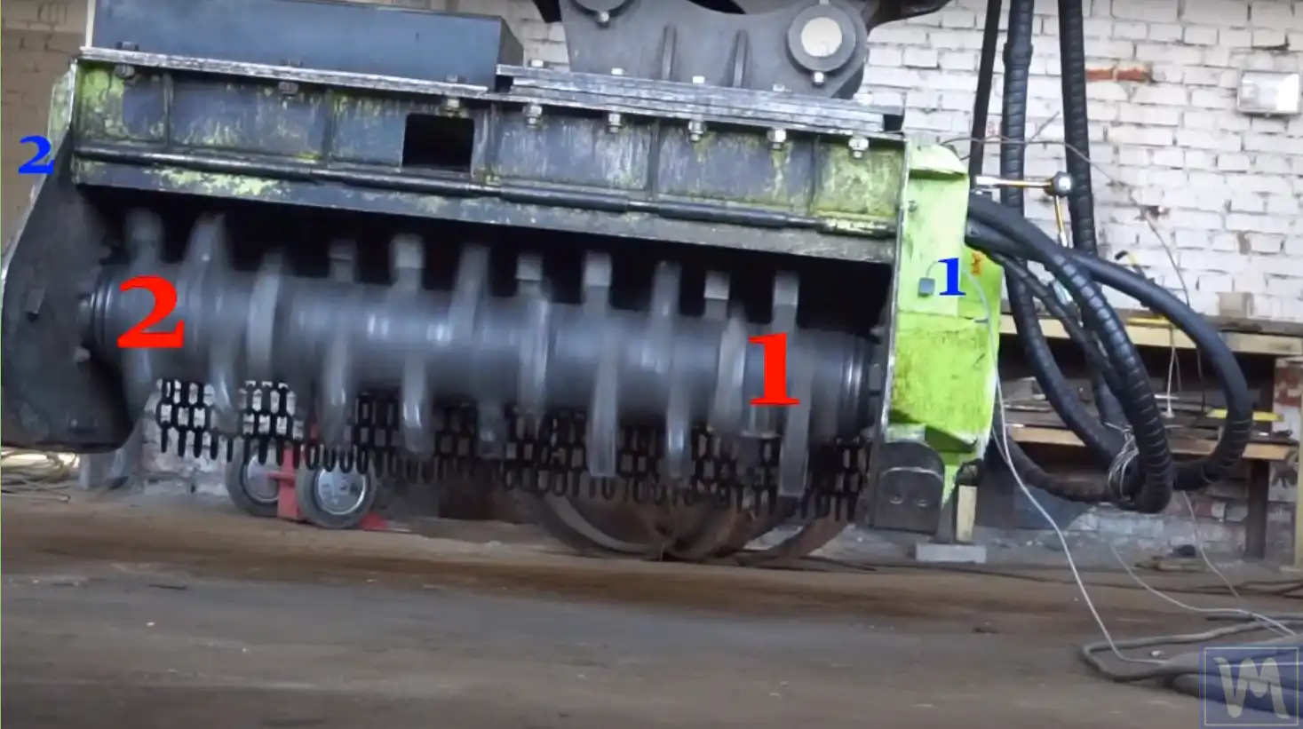
- Комбайн күлтелеу және туралау барабандары
- Берілістік білдектер мен кардандық біліктер
- Көп сатылы сорғы роторлары және компрессор қанатшалар жиынтығы
- Қағаз машинасының біліктері және баспа/жабындау цилиндрлері
- Ұзындығы ~500 мм-ден асатын бұрандалы конвейерлер мен шнектер
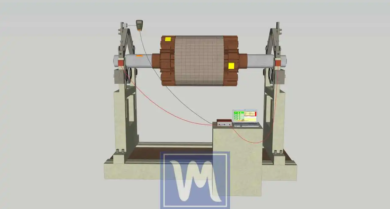
- Осьтік ұзындығы айтарлықтай болатын электр қозғалтқыш роторлары мен генератор роторлары
- Турбокомпрессор роторлары мен бу турбинасы роторлары (далалық дірілді тексеру)
- Бір жазықтықтағы түзетуден кейін бір мойынтіректі дірілі жалғаса беретін кез келген ротор
Төлеу өлшемдері және стандарттар
ISO 21940-11 (formerly ISO 1940-1) defines balance quality grades G0.4 through G4000 for rigid rotors. For rigid rotors — those operating well below their first critical speed — an axial-length-to-diameter ratio above roughly 0.5 usually calls for two-plane balancing. A rotor that operates near or above a critical speed must first be evaluated as a flexible rotor per ISO 21940-12: it may need balancing at several speeds and in more than two planes, so ordinary two-plane rigid-rotor balancing can be insufficient. The permissible residual unbalance per plane is calculated as:
Uper (g·mm) = eper × m / 2, where eper = G × 9549 / n (mm/s × rpm → μm eccentricity), m is the rotor mass in kg, and the factor 2 splits the tolerance equally between the two planes. Note that the equal split is a practical approximation for roughly symmetric rotors with correction planes near the bearings — not a universal ISO allocation rule; ISO 21940-11 allocates the tolerance differently for asymmetric plane and bearing arrangements.
Желдеткіш роторлары әдетте мынадай дәрежеге дейін теңгерімделеді: G6.3 or G2.5 per ISO 14694; дәлдігі жоғары станок шпиндельдері мен жоғары жылдамдықты турбожабдықтар мына нысаналы мәнге бағытталған: G1.0 немесе одан жоғары дәлдікте. Біздің қалдық-дисбалансы калькулятор пайдаланып, жұмысты бастамас бұрын G-дәрежесі, ротор массасы мен жұмыс жылдамдығына арналған рұқсат етілген төзімділікті анықтаңыз.
Balanset-1A — сіздің толық өндіктік-балансталау құраны
Кез келген қатты ротордың — желдеткіштер, барабандар, карданды біліктер, көп сатылы сорғы жиынтықтары — екі жазықтықтағы динамикалық теңгерімдеуі бір портативті құралмен орындалады: Балансет-1А. Бұл — роторларды теңгерімдейтін екіарналы динамикалық теңгерімдегіш және діріл анализаторы олардың өзінің тіліндіктеріндеде, жұмыс жылдамдығында, ықпал коэффициенті әдісін қолданып — бір жазықтық үш іске қосуда, екі жазықтық төртте. Бағдарлама екі жазықтық үшін де дәл түзету массасы мен бұрышын есептеп, есепті сақтайды.
Толық Жиынтықта не бар
€1,975 · Толық комплект, қоймада, ҚДҚ бланкісі
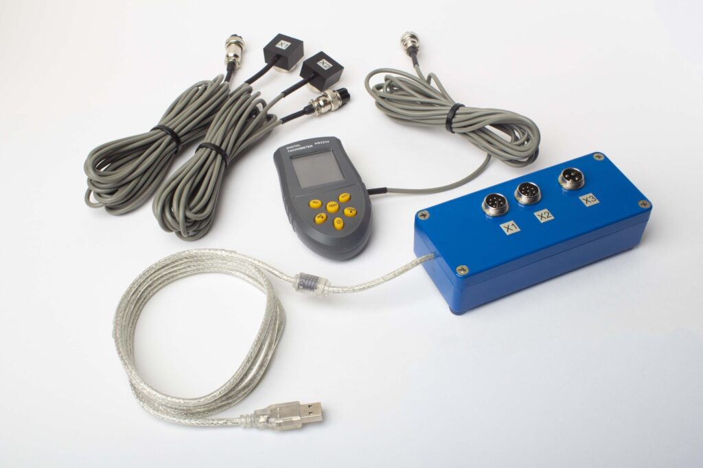
- Өлшеу блогы (USB, 2 канал)
- Екі вибрация акселерометры (4 м кабель, 10 м сөзсіз)
- Лазер тахометр / оптикалық фаза сенсоры (50–500 мм)
- Сенсор үшін магниттік тұрғын
- Сынама және түзету ағырлықтары үшін цифрлық масштаб
- Windows балансировка және талдау бағдарламасы
- Пластикалық тасымалау ыдысы
Full Kit
Блок · 2 датчик · лазерлік тахометр · магниттік тіреуіш · сандық таразы · бағдарлама · тасымалдау жәшігі. Екі жазықтықта теңгерімдеуді дереу бастауға қажеттінің барлығы.
OEM set
Блок · 2 датчик · лазерлік тахометр · бағдарлама. Тіреуіші, таразысы мен жәшігі бар интеграторларға немесе блокты арнаулы теңгерімдеу машинасына орнатушыларға арналған.
| Parameter | Value |
|---|---|
| Өлшеу каналдары | 2 (бір- және екі-жазықтық балансировка) |
| Вибрация қарқындылығының диапазоны | 0.2–80 mm/s RMS |
| Жиілік диапазоны | 5–1000 Hz (≤10% amplitude error above 550 Hz) |
| Өлшеу дәлігі | ±5% толық шкаласынан |
| Method | 3-қоса әсер коэффициенті (1 немесе 2 тегістеу жазықтығы) |
| Analysis | 振幅 & фаза 1×-те, FFT спектрі & толқын түрі, сақталған есептер |
| Laptop | Қоса алынмаған (Windows ПК, сауда бойынша қол жетімді) |
Екі жазықтықта теңгерімдеудің нақты жағдайлары
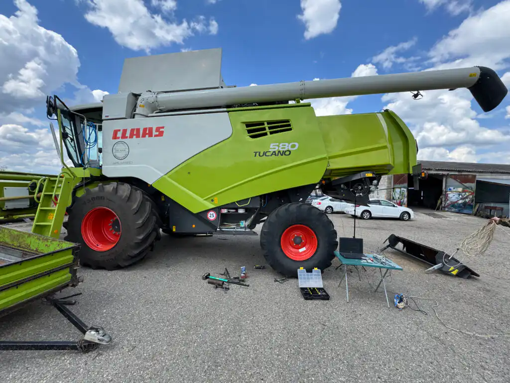
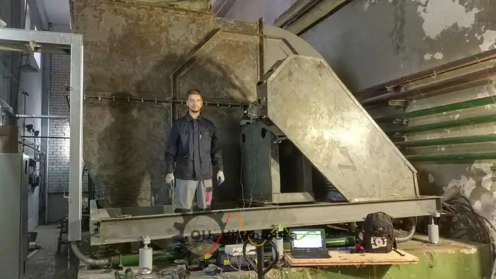
Комбайн барабаны (2 жазықтық)
Ауыл шаруашылығы комбайнында екі түзету жазықтығы да бір далалық сеанс барысында теңгерімделді.
Карданды біліктер (2 жазықтық)
Ұзын карданды білікті динамикалық теңгерімдеу — түзету салмағы әр ұштың фланецінде орнатылды.
Кең экзгаустер дөңгелегі
Кең өнеркәсіптік экзгаустер дөңгелегін орнында екі жазықтықта түзету арқылы теңгерімдеу.
Екі жазықтықта теңгерімдеу — далалық тәжірибеден
Әсер коэффициентін орнату
Екі датчик пен бір лазерлі тахометр екі түзету жазықтығын бір мезгілде сипаттау үшін орналастырылды.
Орнында теңгерімделді
Ротор өз мойынтіректерінде қалады және жұмыс жылдамдығында түзетіледі — алып шығу талап етілмейді.
Екі жазықтық та шешілді
1-жазықтық пен 2-жазықтықтың түзету массасы мен бұрышы бір сеанста бір уақытта есептелді.
Тексерілген нәтиже
Соңғы өту екі жазықтықта да қалдық дисбаланстың ISO 21940-11 рұқсат шегінде екенін растайды.
Екі жазықтықта теңгерімдеуге арналған тегін калькуляторлар
Екі жазықтықта теңгерімдеу бойынша жиі қойылатын сұрақтар
Бір жазықтықта теңгерімдеу қашан жеткілікті?
Екі жазықтықта әсер ету коэффициенттері әдісі қалай жұмыс істейді?
Екі жазықтықта теңгерім жасау жұмысы қанша өлшеу жүрісін талап етеді?
Роторды машинадан алып тастау қажет пе?
Роторым үшін қандай теңгерім сапасы класын нысанаға алу керек?
Техникалық қызмет тобымыз Balanset-1A арқылы екі жазықтықта теңгерімдей ала ма?
Теорияны білік түйінінде
Екі жазықтықты бір барысда шешіңіз — жұмыс жылдамдығында, алып тастаусыз
Balanset-1A сізді толық екі жазықтықты әсер ету коэффициенттері рәсімі арқылы бастайды: бастапқы өлшеу, 1-жазықтықтағы сынақ, 2-жазықтықтағы сынақ, түзету және тексеру — барлығы жұмыс жылдамдығында, ротордың өз мойынтіректерінде. ISO 21940-11, ISO 14694 және API 610 бойынша құжатталған қалдық теңгерімсіздік. Жіберуге дайын.
