Meet Vibromera.com — our new international website. Visit Vibromera.com →

動平衡校正服務 › 主軸與刀柄

CNC 主軸與刀柄動平衡校正 — 於運轉速度下,在機床內進行

高速加工主軸是精密儀器 — 即使在 24,000 rpm 下,僅一毫克的不平衡也會產生具破壞性的離心力。我們對 CNC 主軸及 HSK/BT/CAT 刀柄組件進行動平衡校正 於運轉速度下,在機床內進行,從而改善表面加工品質、延長刀具壽命,並顯著延長主軸軸承的使用壽命。
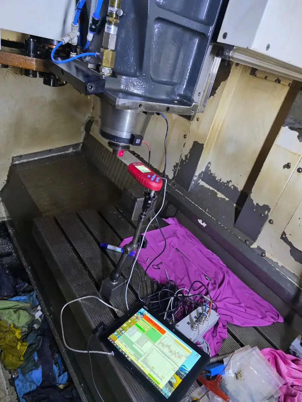
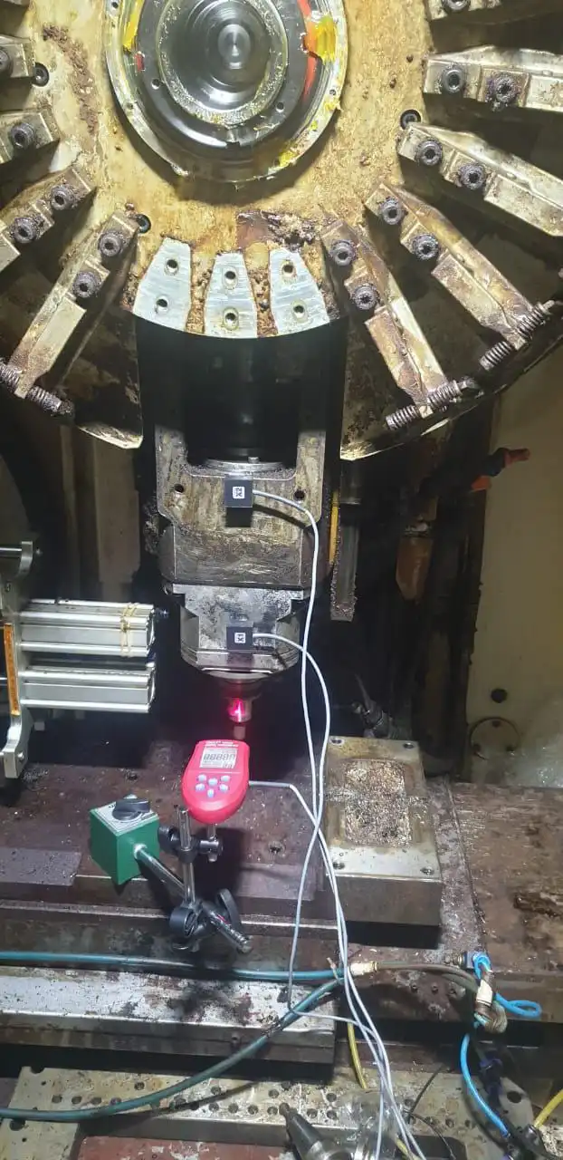
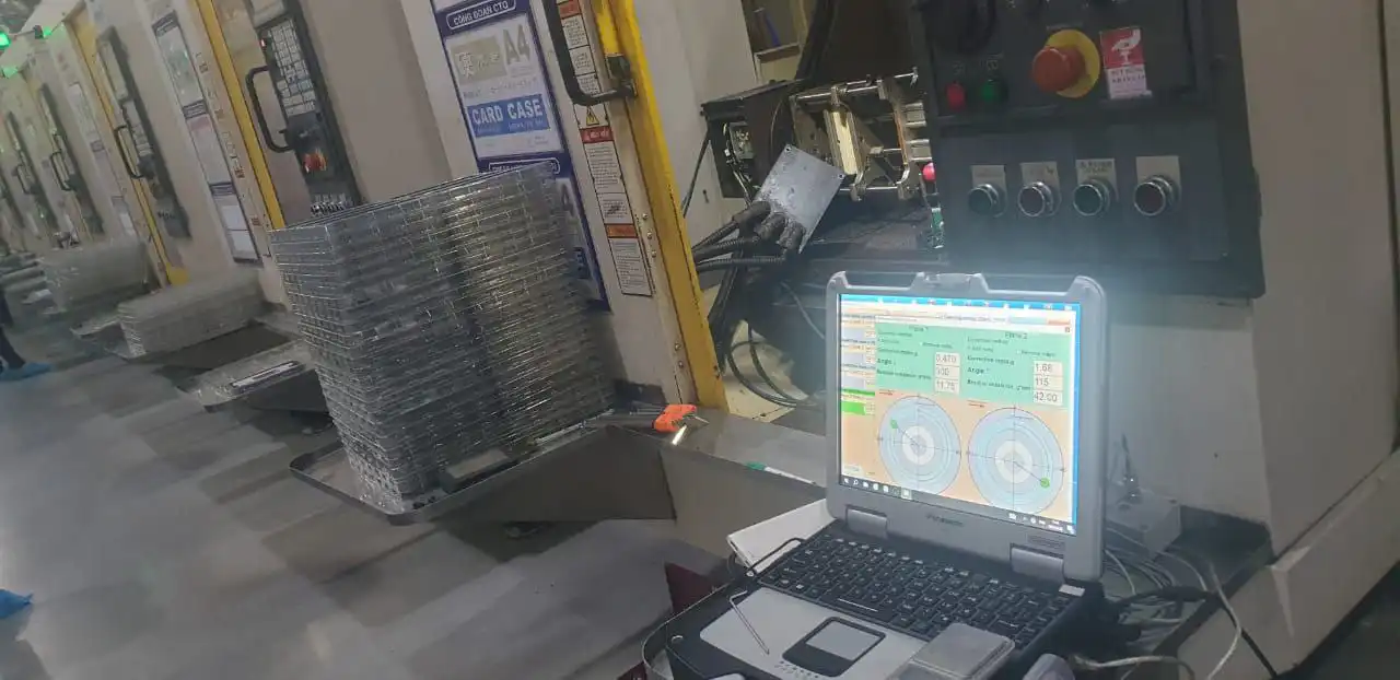
CNC spindle and HSK toolholder balancing with Balanset-1A at operating speed

簡言之: CNC 主軸與刀柄的動平衡校正在實際加工速度下於原位進行 — 無需拆卸主軸,除平衡作業期間外,機床無需停機。安裝於主軸軸承座的振動感測器與安裝於旋轉組件上的雷射測速儀將資料傳輸至 Balanset-1A,該設備採用影響係數法計算精確的校正配重與角度位置。完整組件 — 刀柄、夾頭與切削刀具 — 作為單一單元進行平衡,達到 ISO 21940-11 G1.0 級或更高標準,將殘餘振動降低 70 % 以上,並將主軸軸承壽命延長高達十倍。

主軸或刀柄不平衡的徵兆

高速主軸的不平衡會透過加工工件與主軸組件本身顯現。請留意以下徵兆:

表面加工品質不良 加工表面上隨主軸旋轉重複出現的振紋與波浪紋,表示殘餘不平衡迫使刀具偏離預期路徑。
刀具壽命縮短 不平衡的切削刀具會因切削刃未遵循真實圓周路徑而磨損不均並提前崩刃 — 刀片的一個扇區在每轉中承受不成比例的負荷。
主軸軸承異音 透過主軸軸承座感受到的嗡嗡聲或粗糙感,表示角接觸軸承滾道承受過大的動態徑向負荷。
1× 主軸轉速處的振動峰值 FFT 頻譜在運轉頻率處出現主導峰值 — 而非齒通過頻率或振紋頻率 — 直接指向旋轉組件中的質量不平衡。
異常熱膨脹 前軸承產生的過量熱量會導致主軸熱漂移,使長生產週期中的零件公差發生偏移。
每次更換刀柄後的振動 每個新的刀柄 + 刀具組合都有獨特的不平衡特徵;若更換後未重新進行動平衡校正,該動態負荷將由主軸軸承承擔。

主軸與刀柄為何會失去平衡 — 及其代價

主軸組件是由公差零件堆疊而成 — 主軸軸、拉釘、刀柄錐面、夾頭與切削刀具 — 每個零件都會貢獻其微小的質量不對稱。綜合不平衡至關重要,因為離心力隨轉速的 平方 而增長。在 10,000 rpm 下,僅 1 g·mm 的不平衡就會產生約 1 N 的旋轉徑向力;在 30,000 rpm 下, same 1 g·mm 會產生 9 N。這些力會持續對前角接觸軸承的一個扇區施加負荷,每轉壓縮滾珠軌道。在一個生產班次中,疲勞損傷極為嚴重:本應使用數年的主軸軸承在數月內失效,且組裝時設定的精密預壓會逐漸流失。

表面品質成本的累積同樣迅速。主軸頻率下的振動會引入表面波浪紋,需要額外的精加工工序,提高報廢率,並限制可達到的公差。對於航空航太、醫療與光學零件而言,主軸動平衡校正並非可選維護 — 而是製程設定中的必要步驟。在生產運行前使用 Balanset-1A 對完整組件進行動平衡校正耗時不到一小時,其投資可在節省刀具成本的一天內收回。

×10振動減半時的主軸軸承壽命
−70%單次校正後的典型振動降幅
2一次到訪完成的校正平面數
<1h每個組件的典型現場作業

為何振動減半能倍增軸承壽命

ISO 281 將滾動軸承額定壽命定義為 L10 = (C/P)p,其中 P 為軸承承受的動態負荷,指數 p = 3 適用於滾珠軸承,10/3 適用於滾子軸承。殘餘不平衡 該旋轉徑向負荷 P,且振動振幅直接追蹤它 — 因此將振動減半可使 P 減半,並將軸承壽命延長 2 倍p:約 滾珠軸承約 8×,滾子軸承約 ~10× (210/3 ≈ 10)。在我們的 軸承壽命計算器.

我們如何對 CNC 主軸進行動平衡校正 — 逐步說明

使用 Balanset-1A 對 CNC 主軸進行現場動平衡,遵循影響係數法,在實際加工速度下於機床內進行 — 無需拆卸:

  1. 安裝感測器。 將振動加速規固定於主軸軸承座的前軸承區域,並將雷射測速儀對準刀柄或主軸鼻端的反光相位條。機床在整個過程中保持組裝狀態與正常運轉條件。
  2. 測量基線。 在目標加工速度下運行一次,擷取振動振幅與相位角,建立完整旋轉組件目前不平衡狀態的大小與方向。
  3. 添加試重。 將一小塊校準質量附著於刀柄的平衡環上,或附著於主軸鼻端的專用平衡凸緣上。以相同速度進行第二次運行,量化主軸對該角度位置已知擾動的響應 — 即影響係數。
  4. 讓設備進行計算。 Balanset-1A 求解影響係數方程式,並輸出校正配重及其精確角度位置。對於長組件,或當刀柄平面與主軸鼻端平面均可存取時,雙平面動平衡校正可消除力偶不平衡與靜不平衡。
  5. 安裝校正配重。 平衡環上的調整螺絲、刀柄凸緣的精密切削,或專用夾持配重,可在指示角度施加計算出的校正量。除非試重構成最終校正的一部分,否則應將其移除。
  6. 驗證並記錄。 在運轉速度下進行最終測量運行,確認殘餘不平衡在主軸質量與速度對應的 G2.5 或 G1.0 公差範圍內。Balanset-1A 會儲存帶有時間戳記的報告,包含校正前後數值,以供您的品質記錄使用。

我們校正的部件

  • HSK 刀柄組件(HSK-A25 至 HSK-A100)含刀具
  • BT 與 CAT / ISO 錐面刀柄(BT30、BT40、BT50、CAT40、CAT50)
  • 夾頭主軸與 ER 夾頭組件
  • 面銑刀刀柄與殼式銑刀轉接頭
  • 鏜頭與精密鏜桿
  • CNC 加工中心主軸軸
  • 砂輪機主軸組件
  • 高頻電銑刀與雕刻主軸
  • 車床動力刀具單元
  • 直驅式馬達主軸(平衡運轉速度最高可達約 60,000 rpm,位於儀器 5–1000 Hz 量測範圍內;最佳精度可達約 33,000 rpm)

公差與標準

ISO 21940-11 (formerly ISO 1940-1) defines balance quality grades from G0.4 to G4000 for rigid rotors. For machining spindles and toolholders the applicable grades are G2.5 (general machining up to ~10,000 rpm) and G1.0 (precision and high-speed spindles above 10,000 rpm). The permissible residual unbalance U = e × m (g·mm), where e is the specific unbalance derived from the G-grade and rotational speed, and m is the rotor mass in kg.

對於高速加工組件,除 ISO 21940-11 平衡公差外,驗收標準由主軸與刀柄製造商自身的規格設定。良好實務要求 complete assembly — toolholder, collet, and mounted cutting tool — be balanced as a unit, because each element contributes its own independent mass asymmetry. We measure and document residual unbalance in g·mm and supply a balancing report to the grade your application demands. Use our 殘餘不平衡計算器 to find the permissible tolerance before starting.

Balanset-1A — 您的完整現場動平衡套件

本頁所述的所有作業皆使用單一便攜式儀器完成: Balanset-1A. It is a two-channel dynamic balancer and vibration analyzer that balances CNC spindle and toolholder assemblies 在其自身軸承中、於運轉速度下,採用三次運行影響係數法 — 軟體會計算精確的校正配重與角度,並儲存報告。
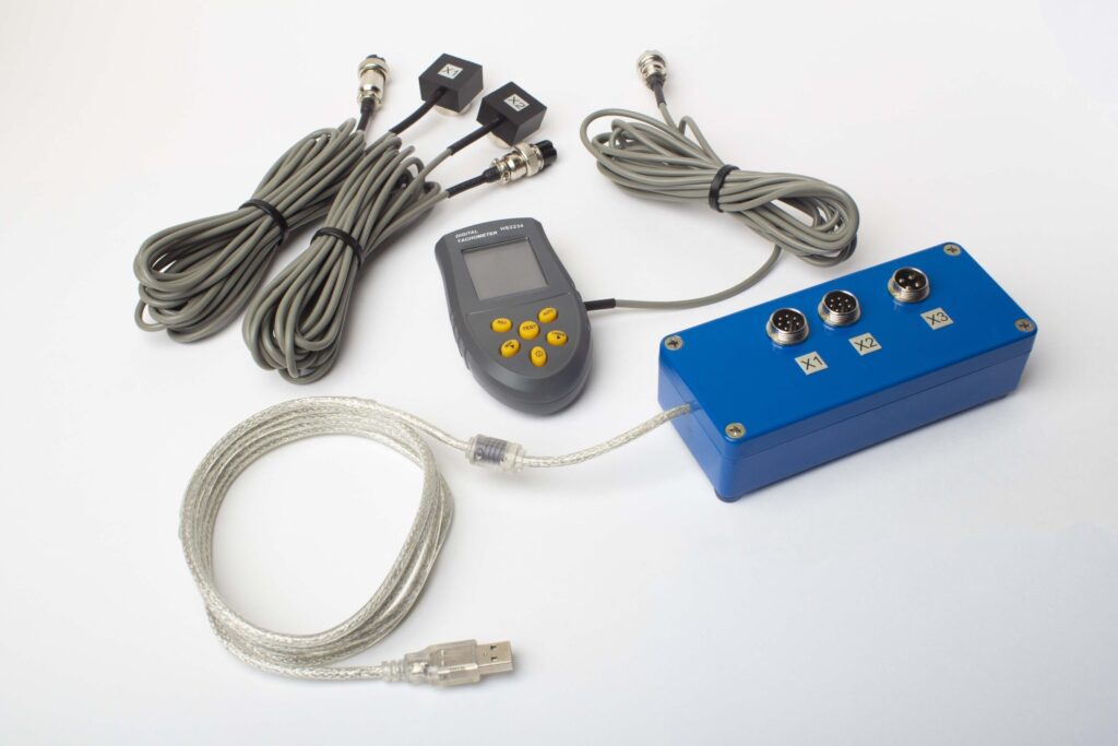
Complete Balanset-1A balancing kit with sensors, laser tachometer, scale and case

完整套件內容

€1,975 · 完整套件,現貨供應,附增值稅發票

  • 介面測量單元(USB,2 通道)
  • 兩支振動加速規(4 m 電纜,10 m 可選)
  • 雷射轉速計 / 光學相位感測器(50–500 mm)
  • 感測器用磁性支架
  • 試重與校正配重用數位秤
  • Windows 動平衡與分析軟體
  • 塑膠運輸箱
推薦

完整套件

主機 · 2 支感測器 · 雷射轉速計 · 磁性支架 · 數位秤 · 軟體 · 運輸箱。開箱即用,具備開始動平衡所需的一切。

OEM

OEM 套件

主機 · 2 支感測器 · 雷射轉速計 · 軟體。適用於已擁有支架、秤與運輸箱的整合商,或將主機嵌入動平衡機器的客戶。

主要技術規格
參數數值
測量通道2(單平面與雙平面動平衡)
振動速度範圍0.2–80 mm/s RMS
頻率範圍5–1000 Hz(>550 Hz 時振幅誤差 ≤10%)
測量精度±5% 滿量程
方法三次運行影響係數法(1 或 2 平面)
分析1× 振幅與相位、FFT 頻譜與波形、已儲存報告
筆記型電腦未包含(Windows PC,可依需求提供)
現貨供應 DHL 葡萄牙 €35 DHL 全球 €110 兩年保固 增值稅發票 工程師支援

In-situ balancing vs balancing machine — which is right for your spindle?

Comparison: field balancing at the CNC machine vs dedicated off-machine balancing stand
係數現場動平衡(Balanset-1A)Dedicated balancing stand (workshop)
Spindle removed from machine?否 — 原地運轉是 — 需完全拆卸
Reflects real running conditions?Yes — actual bearings, thermal preload, drawbar clampingNo — separate spindle emulation
機器停機時間僅安裝感測器(<15 分鐘)數小時至數天(拆卸、運輸、動平衡校正、重新安裝)
校正速度Actual machining speedSeparate, often lower, test speed
Accounts for full assembly (holder + collet + tool)?Yes — complete assembly balanced as one unitDepends on stand; often holder only
符合標準ISO 21940-11 G1.0ISO 21940-11 G1.0
設備成本€1,975(完整套件)€5,000 – €30,000+
Typical job time per assembly<1 小時(現場)Several hours to 1–2 days total

In-situ field balancing is the preferred approach for production spindles that can run, because it captures the true assembled running condition — including thermal preload and drawbar clamping forces — that a separate stand cannot replicate. A dedicated stand remains useful for new-build toolholders before first use or for very high-speed spindles whose geometry prevents direct sensor attachment.

Real spindle-balancing cases

CNC machining-centre spindle and HSK toolholder balanced in-situ at operating speed achieving G1.0

CNC spindle & HSK toolholder

In-situ balancing of a machining-centre spindle and HSK toolholder assembly at operating speed, achieving G1.0 residual unbalance and eliminating surface-finish problems.

Complete toolholder assembly — holder, collet and cutting tool — mounted on spindle for in-machine balancing

Full assembly balanced as one unit

The complete assembly — holder, collet and tool — balanced together in the machine. Each component contributes its own mass asymmetry; assembly-level balancing is required by ISO 21940-11.

Vibration accelerometer mounted on CNC spindle housing at the front-bearing area for field balancing

Sensor at the front-bearing area

The vibration accelerometer is fixed directly to the spindle housing at the front bearing, measuring at full machining speed — no spindle disassembly required.

Spindle & toolholder balancing FAQ

Does the spindle need to be removed from the machine for balancing?
No. The Balanset-1A balances the spindle assembly in its own bearings at the actual machining speed, without any disassembly. A vibration sensor is clamped to the spindle housing and a laser tachometer reads the phase reference on the rotating assembly — that is all the access required. This means the balance result reflects the true running condition, including thermal preload and drawbar clamping forces that a separate balancing stand cannot replicate.
Should I balance the toolholder alone or the full assembly?
Always balance the complete assembly — toolholder, collet, and cutting tool together. Each component has its own mass asymmetry; balancing the holder alone does not account for the tool. ISO 21940-11 toolholder guidelines explicitly require assembly-level balancing for this reason. When you change the tool or regrind the insert, the balance state changes and the assembly should be re-checked before the next production run above 10,000 rpm.
What balance grade do machining spindles need?
G2.5 is acceptable for general-purpose machining at moderate speeds (below ~10,000 rpm). G1.0 is recommended for spindles running above 10,000 rpm and for precision work where surface roughness Ra or Rz tolerances are tight. The permissible residual unbalance in g·mm depends on rotor mass and speed — use our spindle-unbalance calculator to find the exact limit for your application and grade.
How often should toolholder assemblies be balanced?
Best practice for high-speed machining (above 10,000 rpm) is to balance a toolholder assembly whenever a new tool is mounted for a production run. For dedicated long-run setups, rebalance after any regrind, coating process, or toolholder repair that changes mass distribution. Below 10,000 rpm, many shops balance only when vibration symptoms appear, but proactive balancing before a high-value run is always worthwhile.
Can the Balanset-1A handle spindle speeds above 20,000 rpm?
是的。Balanset-1A 的 1× 振動量測範圍為 5–1000 Hz,對應約 300–60,000 rpm 的平衡速度。精度在約 33,000 rpm(550 Hz)以下最佳;超過此速度振幅誤差會增加,但在 1000 Hz 以下仍維持在 10% 以內。實務上,超高速主軸常在降速下進行平衡——只要轉子仍表現為剛性轉子,此方法即有效。使用我們的 spindle-unbalance calculator 以確認您目標運轉速度下允許的 G 級殘餘不平衡。
單一校正平面是否足夠,還是需要兩個?
對於軸向寬度遠小於其直徑的短型、緊湊式刀柄組件,通常只需在刀柄平衡環上設置單一校正平面即可。對於較長的組件(例如銑刀桿或長伸縮刀柄),或當刀柄與主軸鼻端皆可接觸時,雙平面動平衡可消除力偶不平衡與靜不平衡,提供更完整的校正。Balanset-1A 使用相同硬體即可處理單平面與雙平面模式。

在運轉速度下、機床內校正您的 CNC 主軸組件

Balanset-1A 可在不解體的情況下,於運轉速度下量測並解決主軸不平衡,達到 ISO 21940-11 G1.0 公差,並將結果記錄於您的品質檔案中。無需拆卸機床,無生產損失——僅帶來更安靜的主軸、更長的軸承壽命與更好的表面光潔度。


WhatsApp
Balanset-1A · €1975Ask engineer