Understanding Soft Foot



Soft foot is a common condition in rotating machinery in which one or more of a machine’s mounting feet fail to make full, flat contact with the baseplate or foundation they are bolted to. When the hold-down bolts are tightened, the machine’s frame or casing is forced to bend and distort to conform to the uneven mounting surface. That distortion induces significant internal stresses, and those stresses are the hidden root cause of a surprising range of reliability problems — elevated vibration, premature bearing failure, and the inability to hold a precision alignment among them.
A simple analogy is a four-legged chair that rocks because one leg is slightly short. When someone sits on it, the chair’s frame twists until all four legs touch the floor. A machine with a soft-foot condition suffers exactly this kind of frame distortion every single time it is bolted down — except that the “chair” is a precision assembly whose bearing bores and shaft must stay true to within fractions of a millimetre.
1. The Four Types of Soft Foot
Soft foot comes in four recognised forms, and identifying which one you have dictates how you fix it:
- Parallel soft foot: the most common type, in which one foot is simply shorter than the others, leaving a flat, parallel air gap between the foot and the baseplate. It is corrected by adding shims of the measured thickness.
- Angular soft foot: occurs when a foot is bent, or the baseplate is sloped, so the foot touches down at an angle. Tightening the bolt forces the foot to bend flat against the base, springing the frame. A tapered shim or remachining is needed, not a flat stack.
- Squishy (induced) soft foot: caused by excessive corrosion, trapped debris, paint, or too many shims (more than four or five) under a foot. When the bolt is tightened the compressible material squashes down, producing a spongy soft foot. The cure is to clean the surface and consolidate the shim pack.
- External-force soft foot: created by outside forces — pipe strain, conduit, or structural bracing — pulling or pushing on the frame and lifting a foot off the base. No amount of shimming fixes it; the offending external load must be relieved (this is closely related to pipe-strain–induced distortion).
2. Why Soft Foot Is a Major Problem
The frame distortion that soft foot causes is a documented root cause of numerous machinery faults:
- Increased vibration: the internal stresses and distortion create a pre-loaded condition that can sharply raise vibration, frequently showing at running speed (1×) and its harmonics (2×, 3×, and so on) — which makes it easy to mistake for unbalance or misalignment. The distorted frame can also lower the structure’s stiffness toward a frame resonance, compounding the problem.
- Alignment difficulties: precision alignment is impossible while a soft foot exists. As bolts are tightened and loosened during the alignment process the frame shifts unpredictably, so the readings will not repeat. Correcting soft foot is a mandatory prerequisite for precision alignment — every alignment job should begin with a soft-foot check.
- Bearing and seal failure: distortion of the casing distorts the bearing bores, putting uneven loads on the bearings and driving premature bearing wear and failure. It can also pull seals open, producing leaks and the friction patterns associated with seal defects.
- Shaft and coupling stress: the distortion causes internal misalignment of the bearings, which can bend the shaft (a forced shaft bow) and overload the coupling, accelerating coupling defects.
Soft foot is also frequently entangled with general mechanical looseness and pedestal looseness, so a thorough investigation checks for all three together rather than treating them in isolation.
3. How to Detect and Correct Soft Foot
Soft foot is normally found and fixed during a precision-alignment job, using dial indicators or a laser shaft-alignment system. The workflow has three stages:
- Initial check: with every bolt loosened, slide a feeler gauge under each foot to find any obvious gaps. This quick pass often reveals the worst offenders before instruments are even set up.
- Systematic measurement: for a precise result, mount a dial indicator (or the laser system’s soft-foot routine) at each foot. Zero the indicator with the bolt tight, then loosen that one bolt and read how far the foot springs up. A movement greater than about 0.05 mm (0.002 in) typically indicates a soft foot that needs correction. Loosen only one bolt at a time so you isolate each foot’s contribution.
- Correction: add high-quality, pre-cut stainless-steel shims under the soft foot to fill the measured gap, then re-check. Repeat across all feet until loosening any single bolt produces movement within tolerance. Keep the shim count low — stacking too many shims simply re-creates a squishy soft foot.
Calculators that speed the job
Two free tools turn these measurements into action: a soft foot calculator helps quantify the frame distortion from your indicator readings, and a shim thickness calculator converts the measured gap into the exact shim pack to install. Once the feet are flat, a shaft alignment tolerance calculator sets realistic offset and angularity limits for the alignment that follows.
4. Soft Foot in Vibration Diagnostics
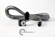
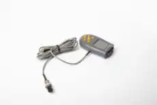
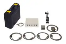
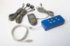
Because soft foot mimics unbalance and misalignment in the spectrum — a strong 1× with harmonics — it is a classic trap for the unwary analyst. The tell-tale is that the symptom changes when a foot bolt is loosened: if the 1× vibration drops noticeably as one bolt is released, frame distortion (not a heavy spot or a bent shaft) is implicated. A practical confirmation is to capture amplitude and phase with a portable two-channel vibration analyser such as the Balanset-1A at each bearing, then loosen each foot bolt in turn and watch how the 1× vector shifts; a foot that swings the phase or collapses the amplitude is the soft one. Clearing soft foot first ensures that any balancing or alignment work afterwards is measuring the true rotor condition rather than chasing a phantom created by a distorted frame and a compromised foundation stiffness.
5. Checking soft foot with the Balanset-1A
With the Balanset-1A you see whether the condition of the feet changes the vibration at the bearings, and whether the correction has actually lowered it.
- With the machine stopped and locked out, fit the two sensors on the bearing housings nearest the suspect feet and set up the tachometer on its reflective mark. Keep them in exactly the same places for every run.
- Run the machine at normal speed, keep clear of it, and open the Vibration Meter window (F5). Wait for the green STABLE bar, then press F9 to freeze a baseline: overall level V1s/V2s, 1× amplitude V1o/V2o and 1× phase F1/F2.
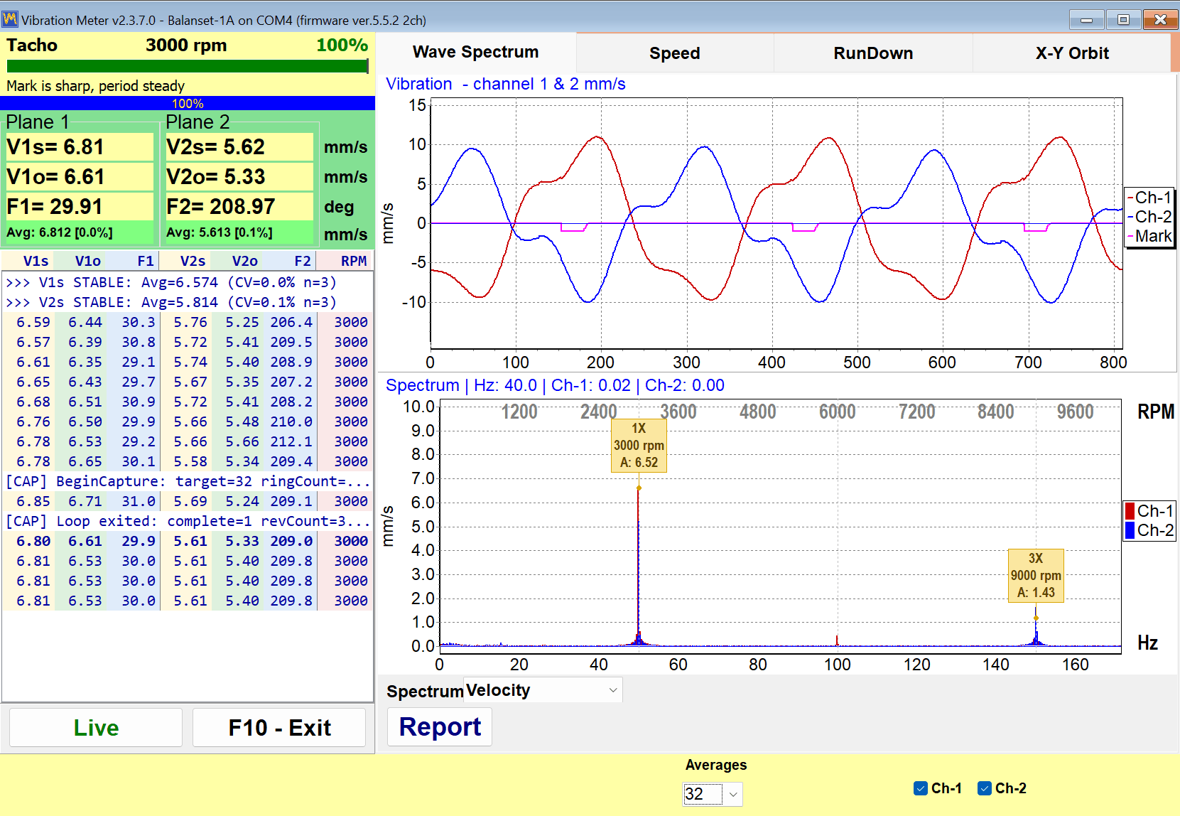
- On the Wave Spectrum tab, read the peaks at the dashed 1×, 2× and 3× guides. If Vo is close to Vs, the vibration is mostly 1×; if Vo is well below Vs, much of it sits in harmonics, a pattern shared by soft foot, looseness and misalignment. Before the first foot change, right-click the spectrum and choose “Y axis: Manual…” so that every later reading is drawn on the same scale.
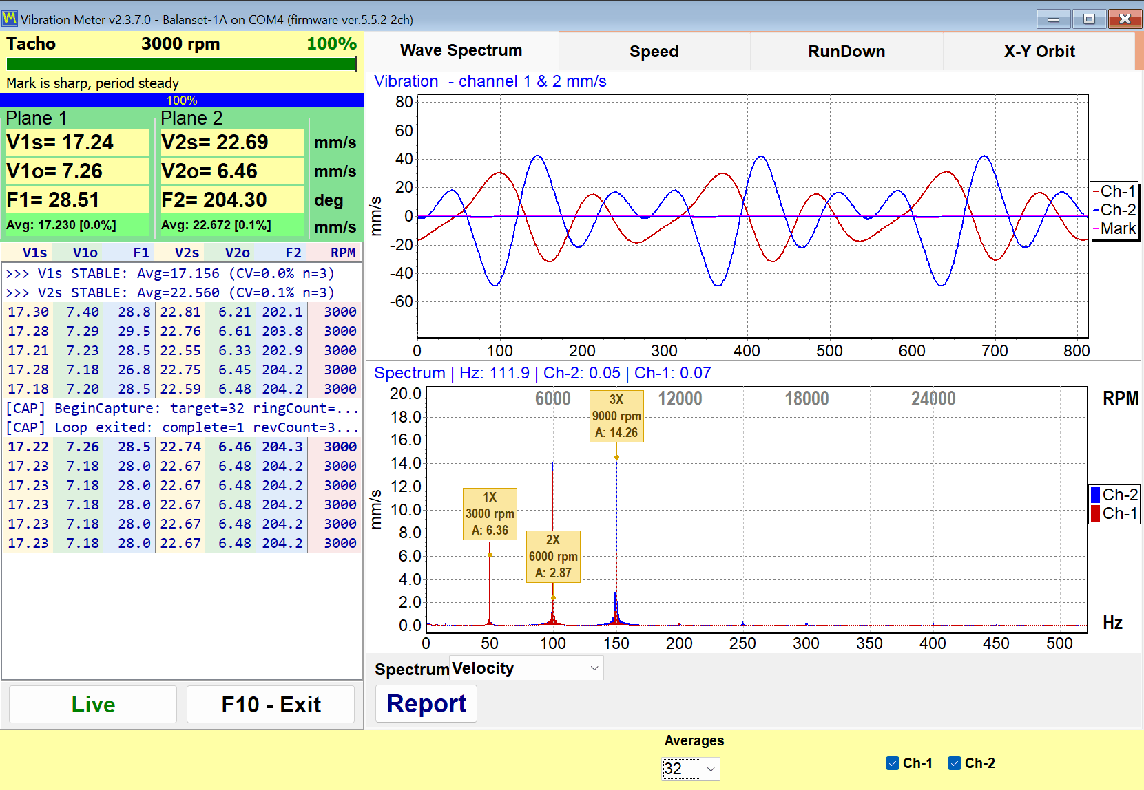
- Stop and lock out the machine for every change: one foot bolt slackened, or a corrected shim pack with all bolts at torque. Restart at the same speed and press F9 again.
- Compare. Normal run-to-run scatter is up to 10–15 % in amplitude and about 10° in phase; a clearly larger change after a single foot change points to that foot. The Trend tab with “Show 1x (Vo)” ticked plots every logged reading against time, so before and after sit on one chart.
Balance only after the feet are corrected and repeated readings agree. If a high 1× remains with the feet flat, record a coast-down on the RunDown tab: an amplitude peak together with a phase rotation of about 180° marks a resonance, and the rotor should not be balanced at that speed.