← Balanset-1A zināšanu bāze — visas nodaļas
Sagatavošanās ir puse no panākumiem. Lielākā daļa neveiksmīgo balansēšanu neizdodas tieši šajā posmā: ierīce mēra mašīnas vibrāciju, kurai ir gultņu brīvkustība vai saplaisājis rāmis, un tās aprēķini nekonverģē.
Universāls kontrolsaraksts (jebkurai mašīnai)
- Gultņa brīvkustība. Noņemiet siksnas / atvienojiet piedziņu un pakustiniet rotoru ar laužņa palīdzību. Jūtamai brīvai kustībai nevajadzētu būt. Ja ir brīvkustība — vispirms nomainiet gultņus, tad balansējiet. Reāls gadījums: 2 mm brīvkustība padarīja balansēšanu neiespējamu, kamēr netika nomainīti gultņi un atjaunota gultņa vieta (uzmetināšana + tapas pārstrāde).
- Plaisas. Pārbaudiet korpusu, rāmi, metinājuma šuves un skriemeļus. Plaisa slodzes ietekmē “elpo” un padara sistēmu nelineāru. Aizmetiniet plaisas. Ir zināms gadījums, kad plaisa skriemelī neļāva veikt balansēšanu.
- Stiprinājumi. Visas balsta, motora un rāmja skrūves pievilktas.
- Rotors darba stāvoklī. Visas lāpstiņas/āmuri/naži savās vietās. Nomainiet nolietotos elementus pa pāriem, viens otram pretī (180° attālumā), pretējā gadījumā jūs paši radīsiet nebalansu.
- Rotors ir tīrs. Sakaltis netīrums, materiāls, ledus — tas arī ir nebalanss, turklāt “klejojošs”.
- Stabili apgriezieni. Piedziņai jāuztur ātrums; starp sērijas mērījumiem starpība ne vairāk kā ~100 apgr./min.
Mulčētāju un pļaujmašīnu specifika
Visbiežāk sastopamā tehnika Balanset-1A lietotāju vidū. Īpatnības:
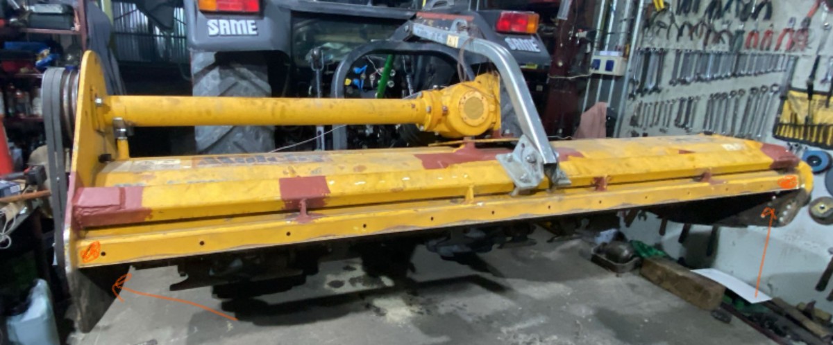
- Paceliet mulčētāju (mašīna gaisā uz hidraulikas) — rotoram jāgriežas brīvi; mašīna nedrīkst balstīties uz sava darba korpusa.
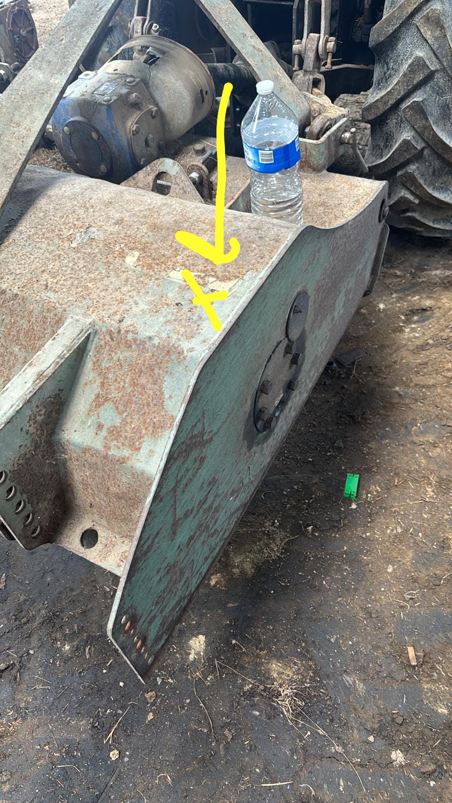
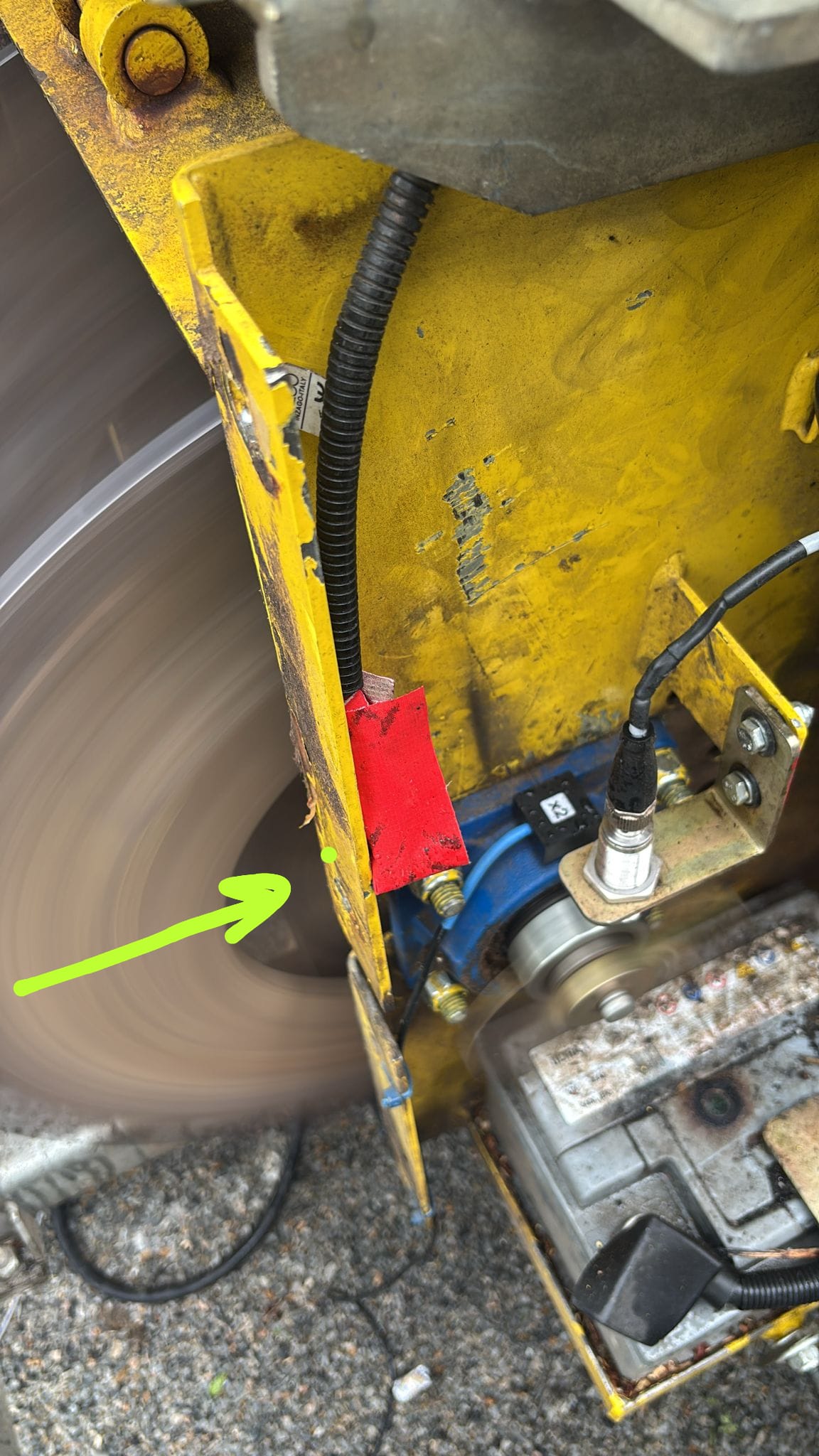
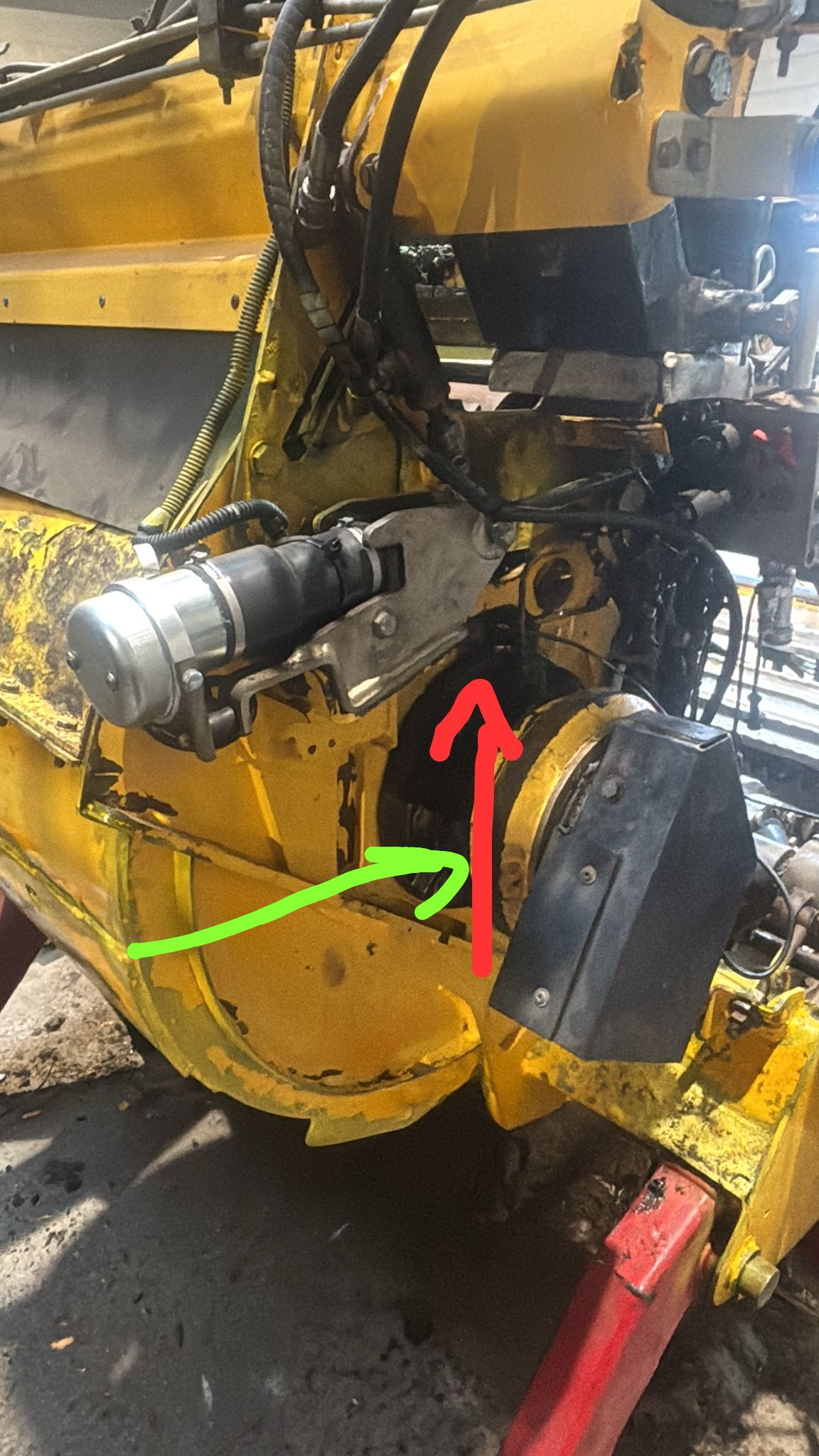
- Priekšējais vāks/aizkars un stumšanas rāmis. Brīvi karājošās detaļas grab un sabojā rādījumus. Balansēšanas laikā tās jāpieķer pie korpusa ar metinājumu, izmantojot metāla starplikas, vai jānoņem. Atbalsta dienests to iesaka atkārtoti: nenostiprināts meža mulčētāja hidrauliskais vāks traucē balansēšanu. Pieredze rāda, ka vāka piemetināšana “atrisina problēmu gandrīz pusē gadījumu”.
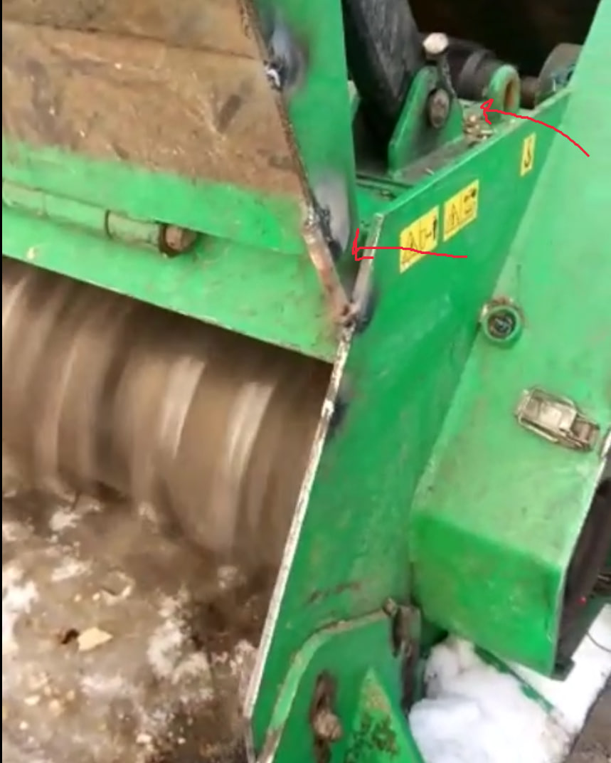
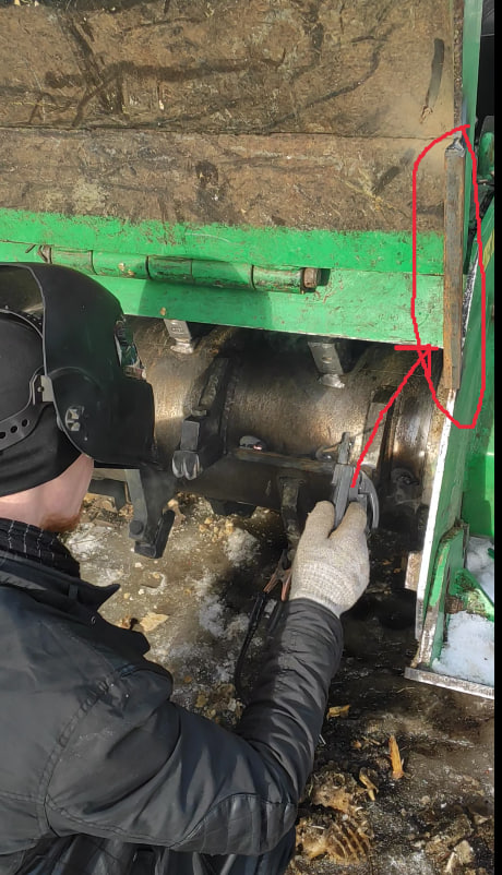
- Āmuri/naži uzstādīti (vēlams jaunus vai vienāda stāvokļa). Balansēt “kailu” rotoru bez darba instrumentiem ir kļūda: ar uzstādītiem nažiem balanss būs cits.
- Brīvi šūpojošies naži (uz ķēdēm vai šarnīriem) netraucē balansēšanu, ja tie nav iestrēguši. Iestrēdzis nazis rada disbalansu.
- Sensori — gultņa korpusu augšpusē vai sānā, nevis uz rotora gala plāksnes.
- Ņemiet vērā metinājuma šuves masu: atsvara piemetināšana pievieno aptuveni 100 g metinājuma metāla — to var pamanīt precīzās koriģēšanas posmā.
Kur uzstādīt sensorus
- Sensors tiek novietots uz gultņa korpusa, cik vien iespējams tuvu gultnim, uz tīras plakanas vietas (magnētam jāpieguļ cieši).
- Mērīšanas ass ir radiāla (parasti horizontāla, šķērsām rotora asij). Horizontālais virziens parasti ir „mīkstāks“ un dod lielāku signālu.
- X1 — 1. plakne (piemēram, kreisais balsts), X2 — 2. plakne (labais). Atcerieties, kurš ir kurš, un nesajauciet tos, kamēr darbs nav pabeigts.
- Nostipriniet kabeļus tā, lai rotors tos nevarētu ievilkt. Kabeļa ievilkšana rotorā ir biežākais sensora bojājuma cēlonis.
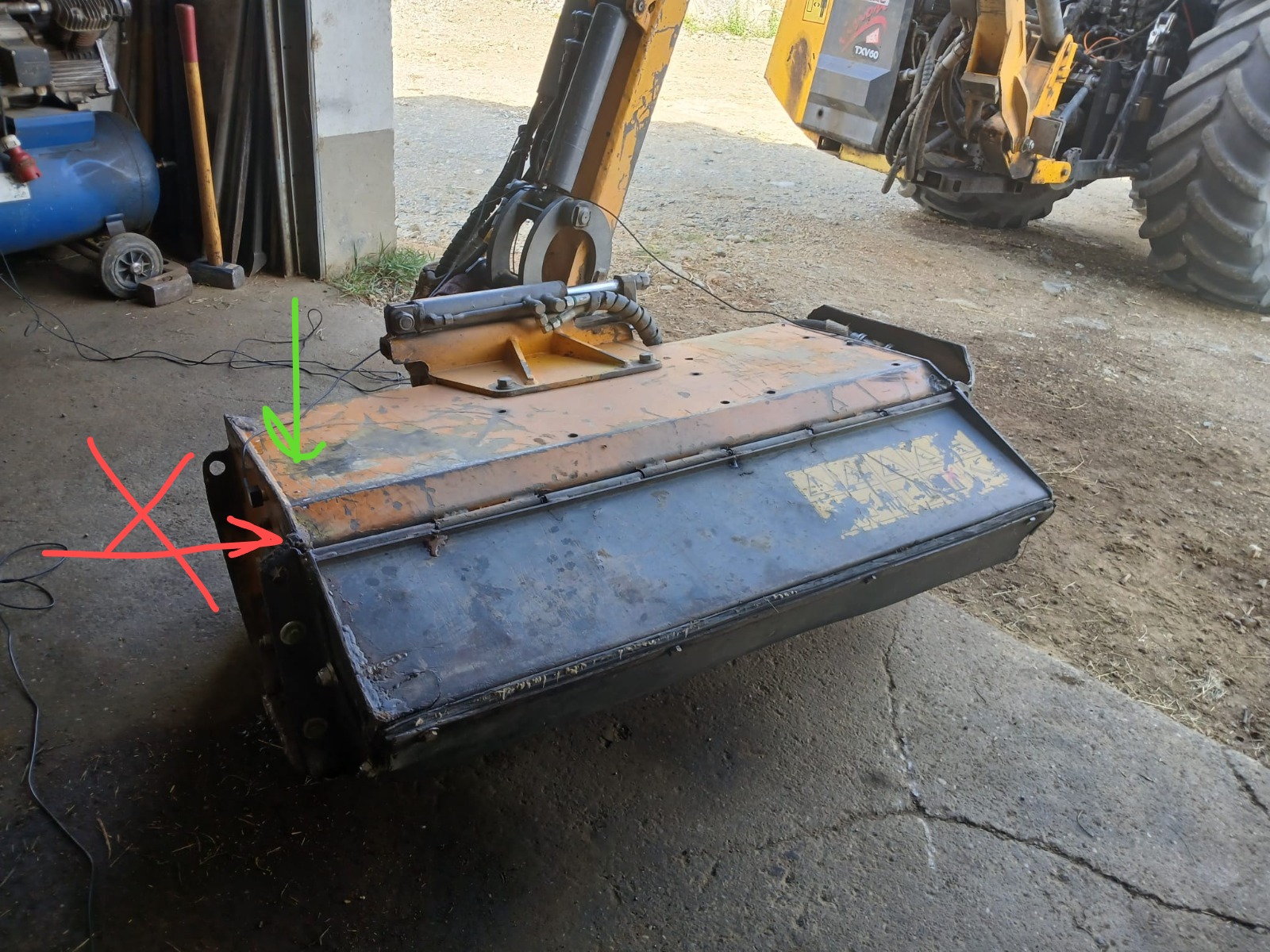
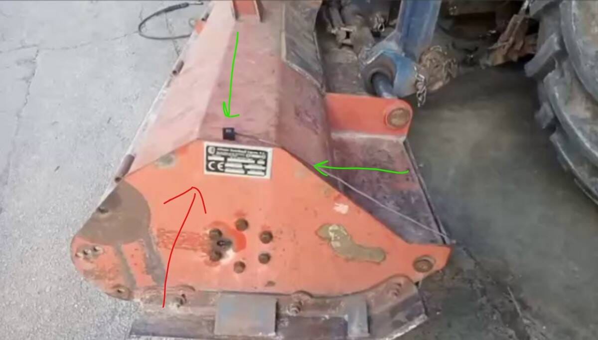
Konsolveida rotori (ventilatori uz motora vārpstas)
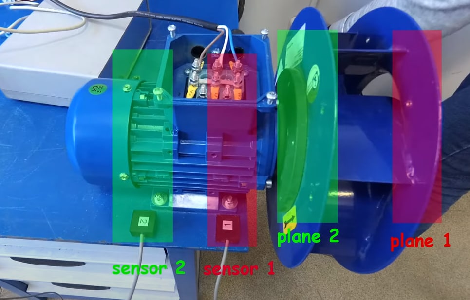
Konsolveida rotoram (darbrats atrodas vārpstas galā, kā vairumam centrbēdzes ventilatoru) korekcijas plaknes atrodas uz paša darbrata priekšējā un aizmugurējā diska, bet sensorus uzstāda uz motora gultņu korpusiem. Sensora un plaknes atbilstību diagrammā norāda krāsa: 1. sensors atbilst 1. plaknei (ārējam diskam), bet 2. sensors atbilst 2. plaknei (iekšējam diskam, tuvāk motoram).
Tahometrs un atzīme
- Uzlīmējiet atstarojošās lentes gabaliņu uz rumbas vai vārpstas, nevis uz lāpstiņas vai spīdīgas virsmas.
- Tahometrs uz magnētiskā statīva, stars uz atzīmi nelielā leņķī, attālums pēc rokasgrāmatas. Novietojiet statīvu uz nevibrējošas virsmas.
- Pārbaude: programmā norādītajiem apgriezieniem jāsakrīt ar reālajiem un jābūt stabiliem. Parastās lamatas (saule, atspulgs, dubultas atzīmes) — 8. nodaļa.
- Kad mērījumu sērija sākta, nepārlīmējiet atzīmi un nepārvietojiet tahometru.
Testa mērījums vibrometra režīmā
Pirms balansēšanas iedarbiniet mašīnu un vērojiet vibrometra režīmā:
- Apgriezieni tiek nolasīti un ir stabili.
-
Kopējā vibrācija un 1x komponente ir stabilas no viena mērījuma līdz nākamajam (amplitūdas izkliede < 10–20%, fāzes izkliede < 10–20°).
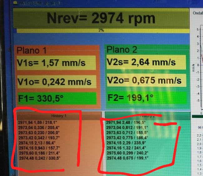
- Novērtējiet sākotnējo līmeni: ja kopējā vibrācija ir liela (30–50+ mm/s), visticamāk, ir mehāniska problēma vai rezonanse; virs 50 mm/s atbalsta dienests iesaka balansēt divos posmos, sākot ar samazinātiem apgriezieniem.
- Skatieties spektrā: ja dominē 1x — tas ir labi, tas ir disbalanss, balansēšana palīdzēs. Ja dominē 2x un augstāk, vai pīķi ārpus rotācijas frekvences — vispirms atrodiet cēloni (7. nodaļa).
Balansēšanas apgriezienu izvēle
- Ideālā gadījumā — darba apgriezieni. Bet ja darba apgriezieni sakrīt ar rezonansi vai vibrācija ir ārpus skalas, sāciet zemāk: mulčētājiem parasti 600–900 apgr./min, pēc tam pakāpeniski paaugstiniet.
-
RunDown (izskrējiena) grafiks palīdz atrast “tīrus” apgriezienus: rezonanses pīķi ir uzreiz redzami — balansējiet starp tiem. Reāls piemērs: stenda rezonanses pie ~420 un ~644 apgr./min → balansēšana pie ~844 apgr./min.
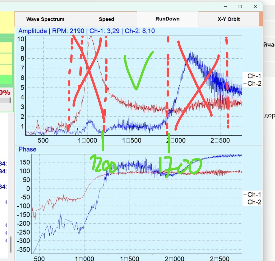
RunDown ar atzīmēm: rezonanses zonas nosvītrotas, darba zona atzīmēta. 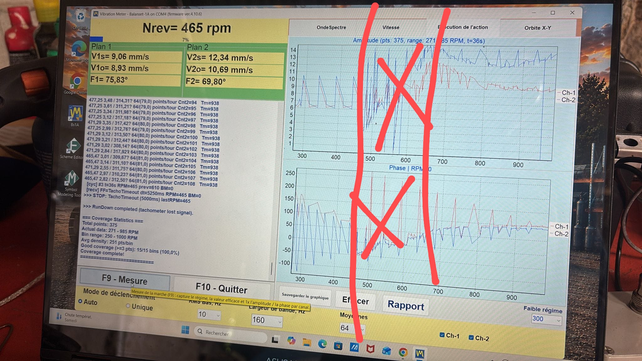
RunDown darbā uz lauka. - Visiem vienas sērijas mērījumiem jābūt pie vieniem un tiem pašiem apgriezieniem.
Izmēģinājuma atsvara izvēle
Izmēģinājuma atsvaram jāmaina vibrācija, citādi ierīcei nav no kā aprēķināt. Kritērijs: amplitūdas izmaiņa par 20–30% vai fāzes izmaiņa par 20–30° pēc izmēģinājuma atsvara uzstādīšanas.
Praktiskie orientieri:
- pļaujmašīnas, vieglie mulčētāji: 200–300 g;
- lieli mežsaimniecības mulčētāji: 500–700 g;
- ~600 kg rotors: 400–600 g;
- ļoti lieli rotori (tonnas): kilogrami (1,7 t rotoram vajadzēja ~1 kg).
Atbalsta dienesta novērtēšanas formula (rotora masa Mr kg, stiprinājuma rādiuss Rp m, apgriezieni N):
Mp ≈ Mr / (Rp × (N/100))² [kg]Programmatūrā ir arī izmēģinājuma atsvara kalkulators (vibromera.eu/content/trial-weight-calculator/). Ja atsvars ir pārāk mazs, izmaiņa pazūd troksnī (reāls gadījums: 3–7 g uz turbīnas gandrīz neko nemainīja; 5 g deva rezultātu, kad samazināja fona troksni). Pārāk liels atsvars izraisa sistēmas nelineāru reakciju.
Nostipriniet atsvaru droši: skava, skrūve, magnēts pie zemiem apgriezieniem — bet tā, lai tas nevarētu nolidot. Nosveriet to ar komplekta svariem.

