← Base de connaissances Balanset‑1A — tous les chapitres
La préparation représente la moitié du travail. La plupart des équilibrages qui échouent butent précisément sur cette étape : l'appareil mesure les vibrations d'une machine dont les roulements présentent du jeu ou dont le châssis est fissuré, et ses calculs ne convergent pas.
Liste de contrôle universelle (toute machine)
- Jeu de roulement. Retirez les courroies / débrayez l'entraînement et faites bouger le rotor avec un pied-de-biche. Il ne doit y avoir aucun jeu perceptible. Jeu = remplacer d'abord les roulements, puis équilibrer. Cas réel : 2 mm de jeu ont rendu l'équilibrage impossible jusqu'au remplacement des roulements et à la restauration de la portée (rechargement par soudure + réusinage du tourillon).
- Fissures. Inspectez le corps, le châssis, les cordons de soudure, les poulies. Une fissure “respire” sous charge et rend le système non linéaire. Soudez les fissures. Un cas connu : une fissure dans une poulie a bloqué l'équilibrage.
- Éléments de fixation. Tous les boulons de support, de moteur et de châssis serrés.
- Le rotor en état de fonctionnement. Toutes les lames/tous les marteaux en place. Remplacez les éléments usés par paires, l'une en face de l'autre (à 180°), sinon vous créez vous-même un balourd.
- Le rotor est propre. Les dépôts de saleté, de matière ou de glace sont aussi du balourd — et un balourd “instable”.
- Régime stable. L'entraînement doit maintenir sa vitesse ; entre les essais d'une même série, pas plus de ~100 RPM d'écart.
Particularités des broyeurs et tondeuses
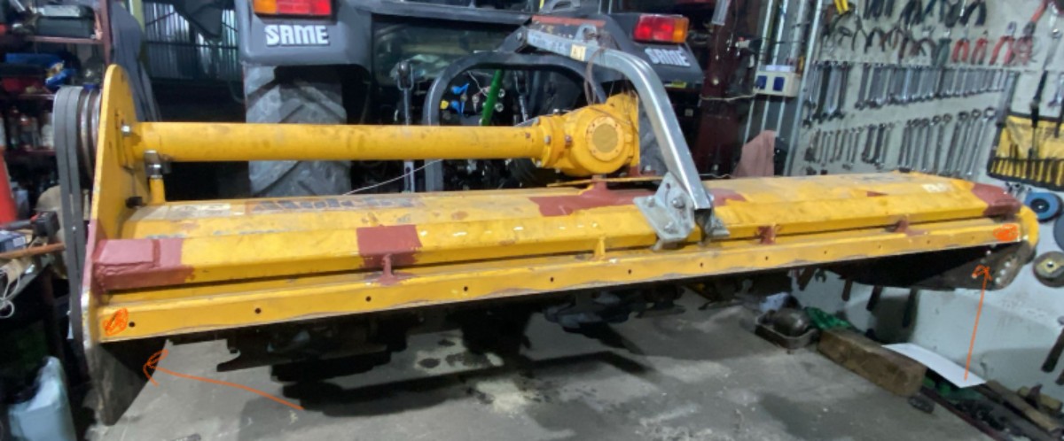
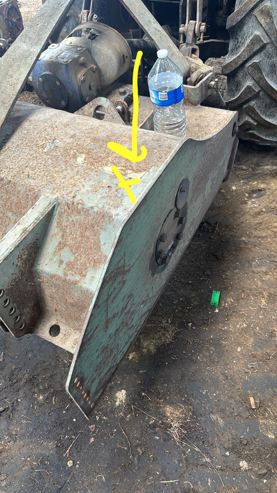
Les machines les plus courantes chez les utilisateurs de Balanset‑1A. Les particularités :
- Soulevez le broyeur (machine soulevée sur l'hydraulique) — le rotor doit tourner librement ; la machine ne doit pas reposer sur son organe de travail.
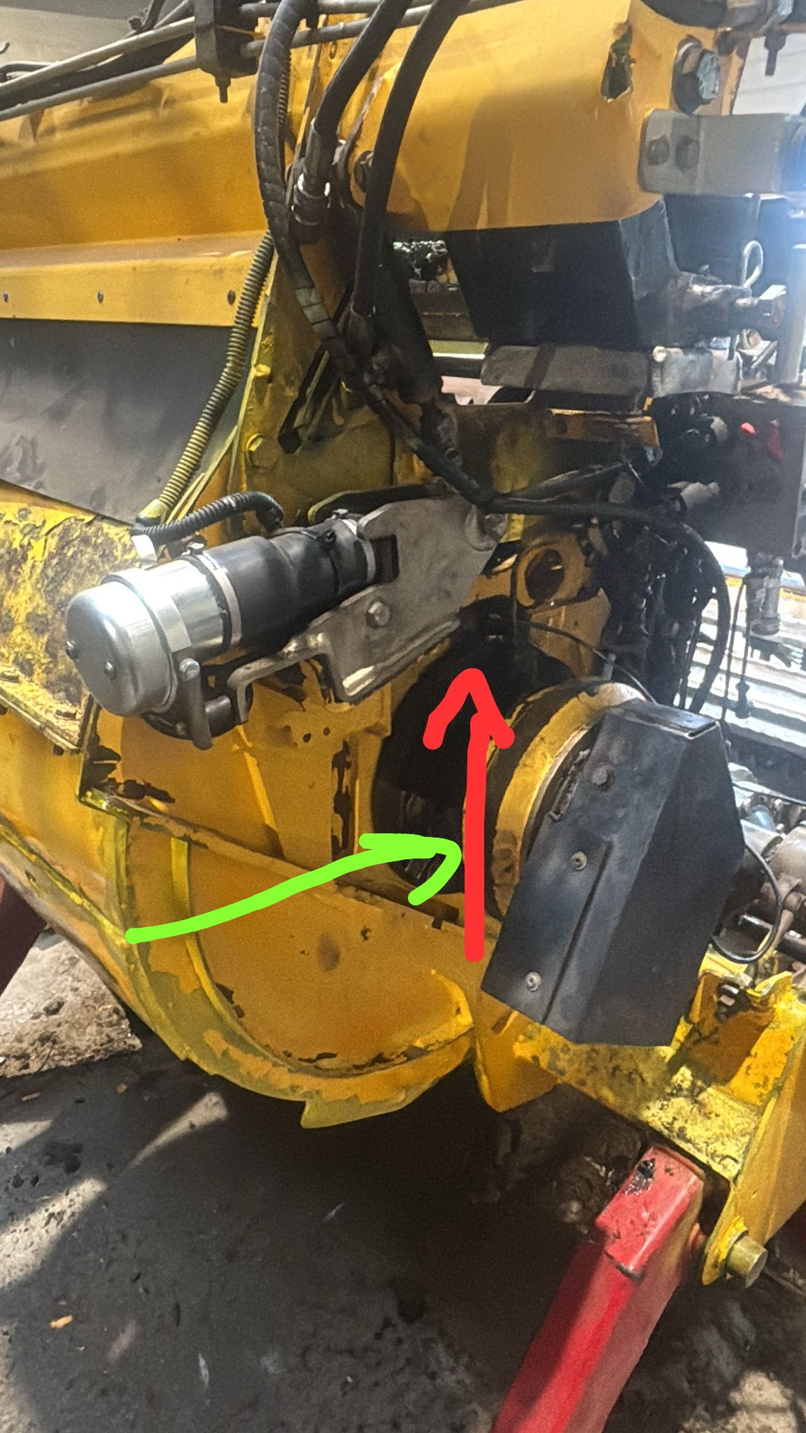
- Le volet/rideau avant et le châssis du pousseur. Les pièces qui pendent librement s'entrechoquent et faussent les mesures. Elles doivent être pointées au corps à l'aide d'entretoises métalliques (le temps de l'équilibrage) ou déposées. C'est une recommandation récurrente du support technique : un volet hydraulique non fixé d'un broyeur forestier compromet l'équilibrage. Selon l'expérience, souder le volet « résout le problème dans près de la moitié des cas ».
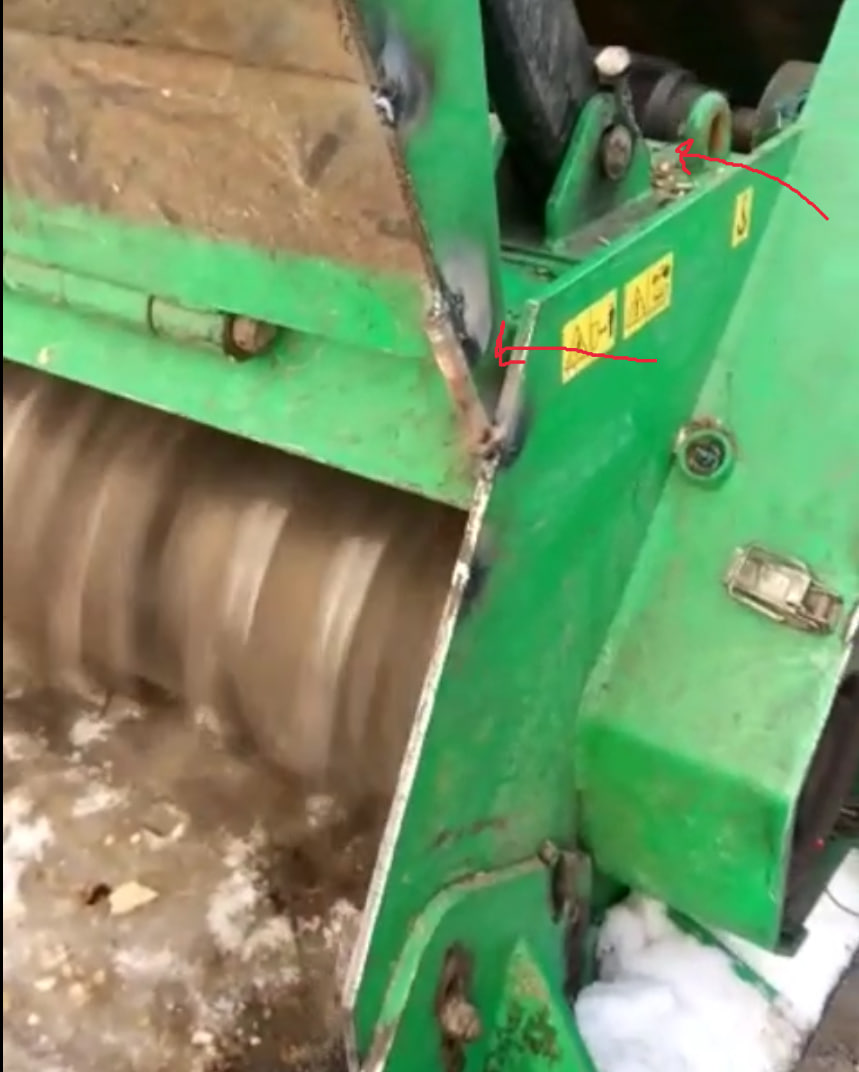
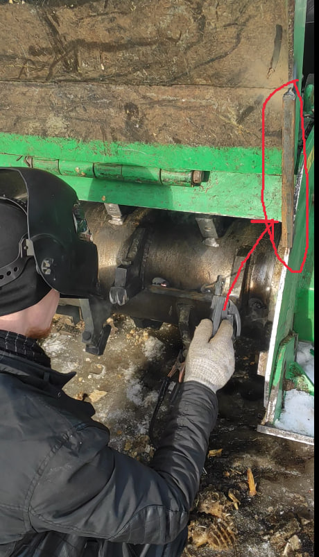
- Marteaux/lames installés (de préférence neufs ou dans un état équivalent). Équilibrer un rotor “nu”, sans les organes de travail, est une erreur : une fois les lames montées, l'équilibrage sera différent.
- Lames libres oscillantes (à chaîne ou articulées) ne gênent pas l'équilibrage tant qu'elles ne sont pas grippées. Une lame grippée crée un balourd.
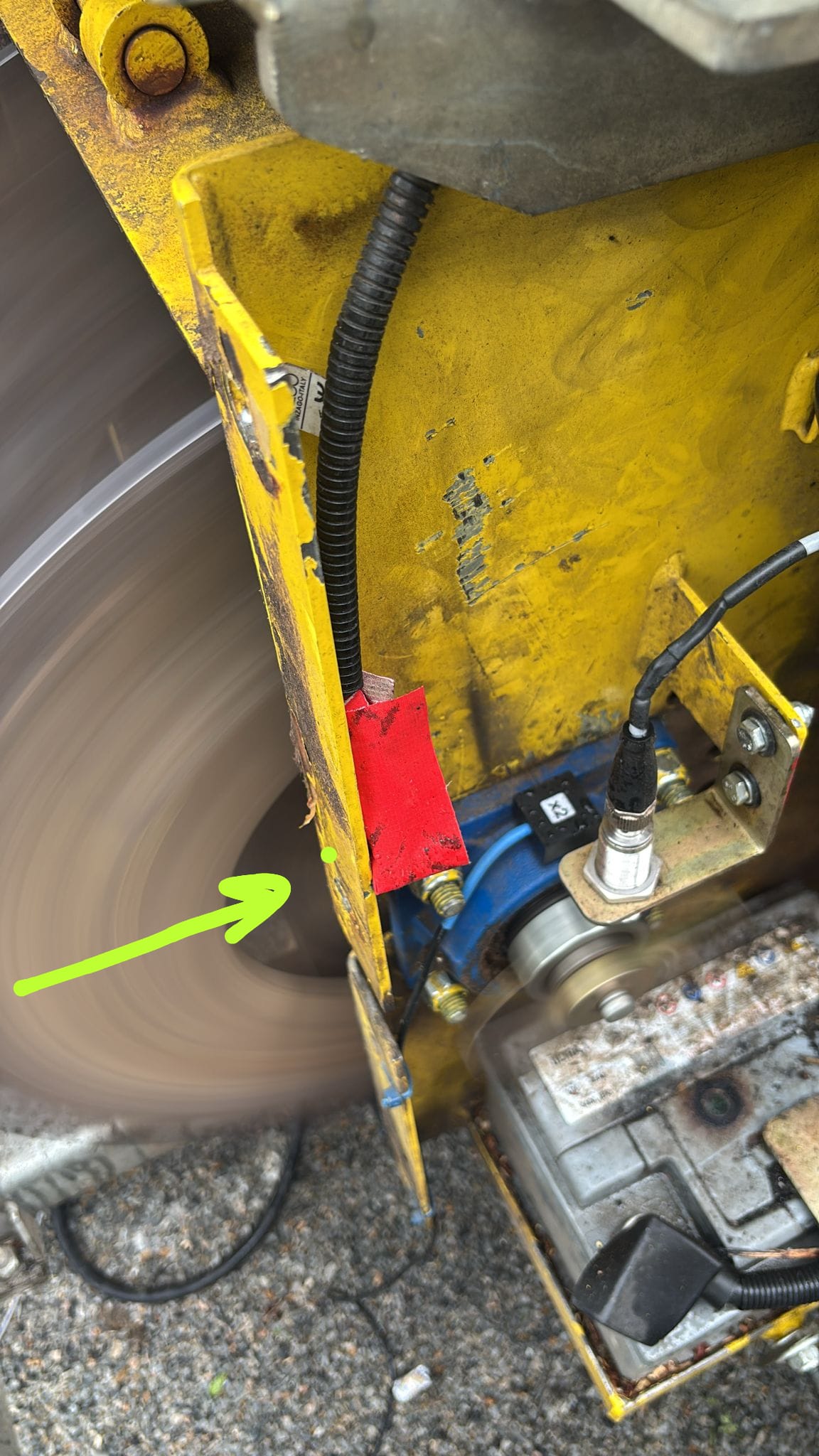
- Capteurs — sur le dessus ou sur le côté des corps de roulement, pas sur la face frontale du rotor.
- Tenez compte de la masse du cordon de soudure : souder une masse ajoute ~100 g de métal d'apport — sensible au stade de la finition.
Où monter les capteurs
- Le capteur se place sur le corps du roulement, le plus près possible du roulement, sur une zone plane et propre (l'aimant doit être bien plaqué).
- Axe de mesure — radial (généralement horizontale, transversale à l'axe du rotor). La direction horizontale est généralement plus “souple” et donne un signal plus important.
- X1 — plan 1 (par exemple le palier de gauche), X2 — plan 2 (le palier de droite). Retenez cette correspondance et ne les intervertissez pas avant la fin du travail.
- Fixez les câbles pour qu'ils ne puissent pas être entraînés dans le rotor. C'est la cause la plus fréquente de destruction d'un capteur.
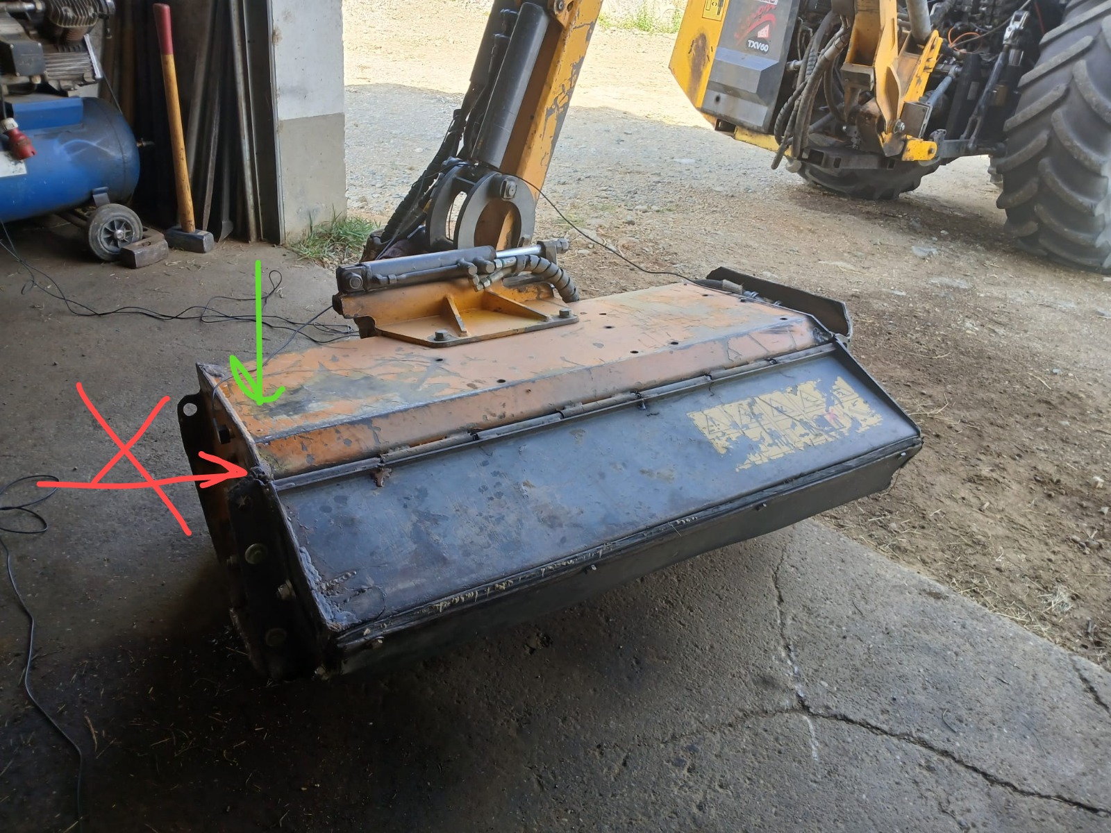
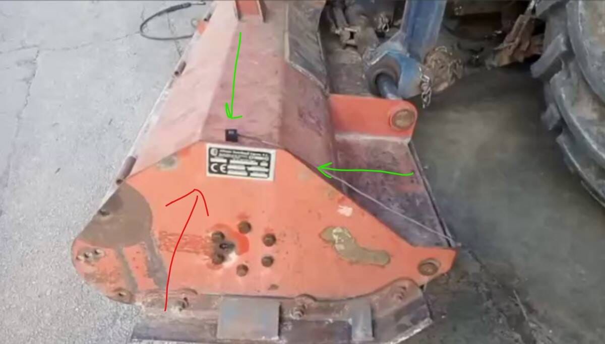
Rotors en porte-à-faux (ventilateurs sur l'arbre moteur)
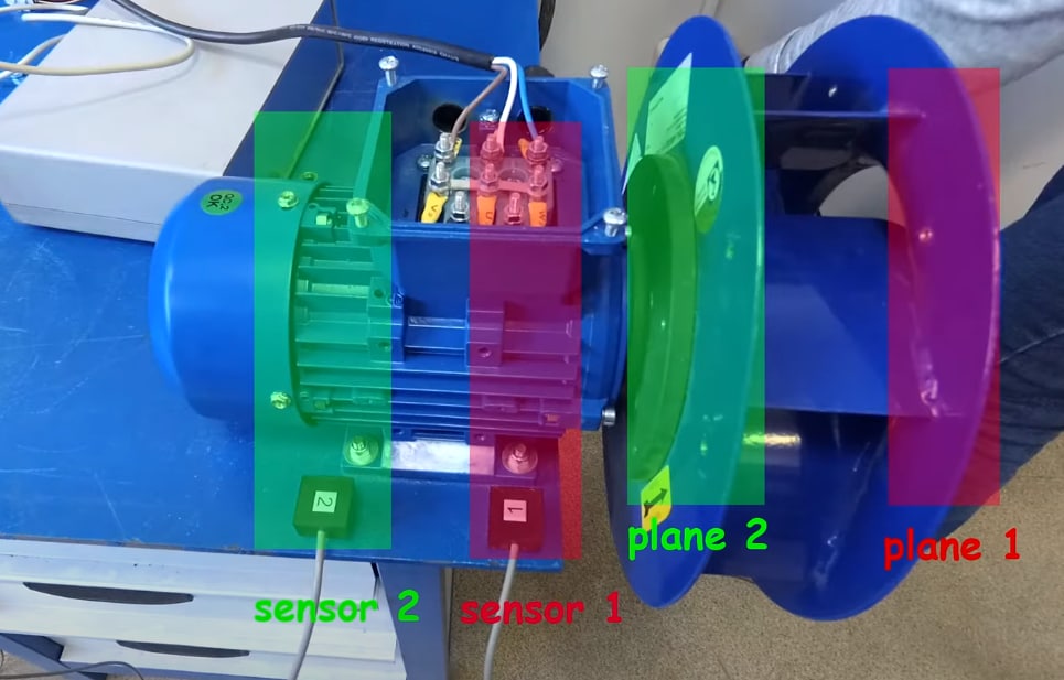
Sur un rotor en porte-à-faux (la roue se trouve à l'extrémité de l'arbre, comme sur la plupart des ventilateurs centrifuges), les plans de correction se situent sur la roue elle-même, sur les disques avant et arrière. Les capteurs se placent sur les logements de roulement du moteur. Le schéma indique par couleur la correspondance entre capteurs et plans : le capteur 1 correspond au plan 1 (disque extérieur), et le capteur 2 au plan 2 (disque intérieur, plus proche du moteur).
Tachymètre et repère
- Collez un morceau de ruban réfléchissant sur le moyeu ou arbre pas sur une lame et pas sur une surface brillante.
- Tachymètre sur le support magnétique, faisceau dirigé sur le repère avec un léger angle, à la distance indiquée dans le manuel. Placez le support sur une surface qui ne vibre pas.
- Vérifiez : le régime indiqué dans le logiciel doit correspondre à la réalité et être stable. Les pièges habituels (soleil, reflets, repères doubles) — chapitre 08.
- Une fois la série de mesures commencée, ne recollez pas le repère et ne déplacez pas le tachymètre.
Un essai en mode vibromètre
Avant d'équilibrer, démarrez la machine et observez le mode vibromètre :
- Le régime s'affiche et est stable.
-
La vibration globale et la composante 1x sont stables d'un essai à l'autre (dispersion d'amplitude < 10–20 %, de phase < 10–20°).
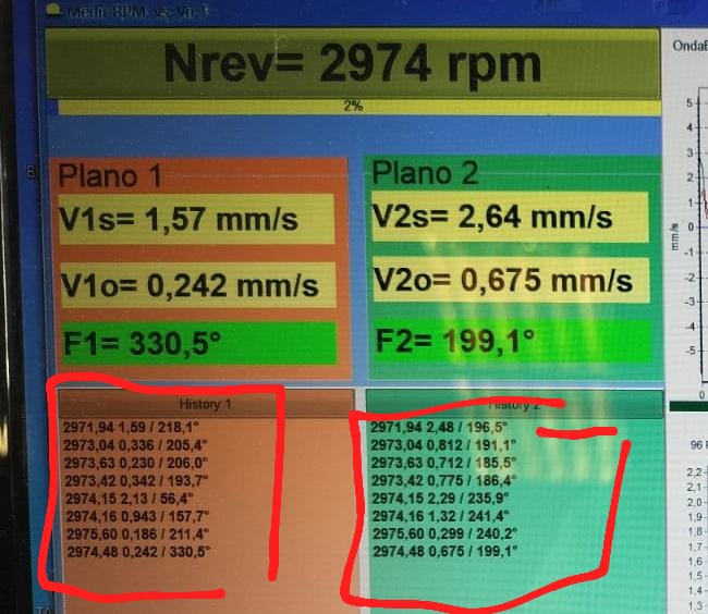
- Évaluez le niveau de départ : si la vibration globale est énorme (30–50+ mm/s), il s'agit très probablement d'un problème mécanique ou d'une résonance ; au-delà de 50 mm/s, le support technique recommande d'équilibrer en deux étapes, en commençant à un régime réduit.
- Regardez le spectre : une dominante en 1x est une bonne nouvelle — c'est du balourd, l'équilibrage aidera. Une dominante en 2x ou plus, ou des pics éloignés de la fréquence de rotation — cherchez d'abord la cause (chapitre 07).
Choisir le régime d'équilibrage
- Idéalement — le régime de travail. Mais si le régime de travail tombe sur une résonance ou si la vibration sort de l'échelle, commencez plus bas : pour les broyeurs, typiquement 600–900 rpm, puis remontez progressivement.
-
Le graphique RunDown (ralentissement en roue libre) aide à trouver un régime “propre” : les pics de résonance sont immédiatement visibles — équilibrez entre eux. Exemple réel : résonances du banc d'essai à ~420 et ~644 RPM → équilibrage à ~844 RPM.
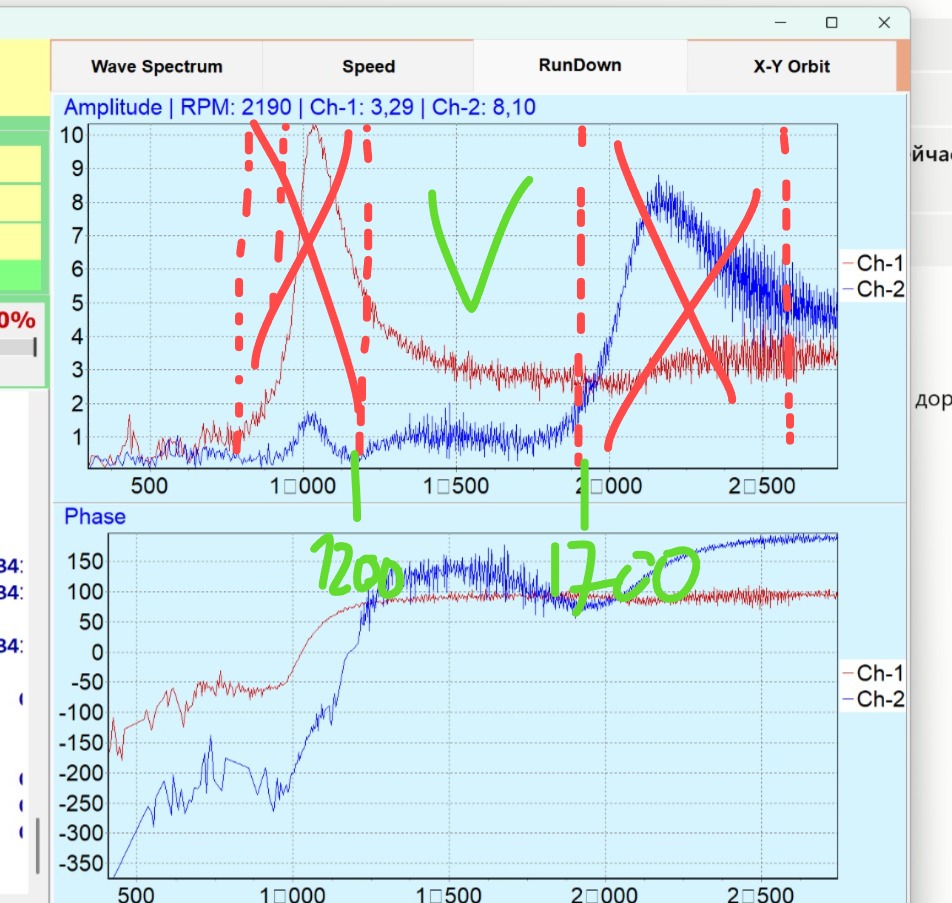
RunDown annoté : zones de résonance barrées, zone de travail cochée. 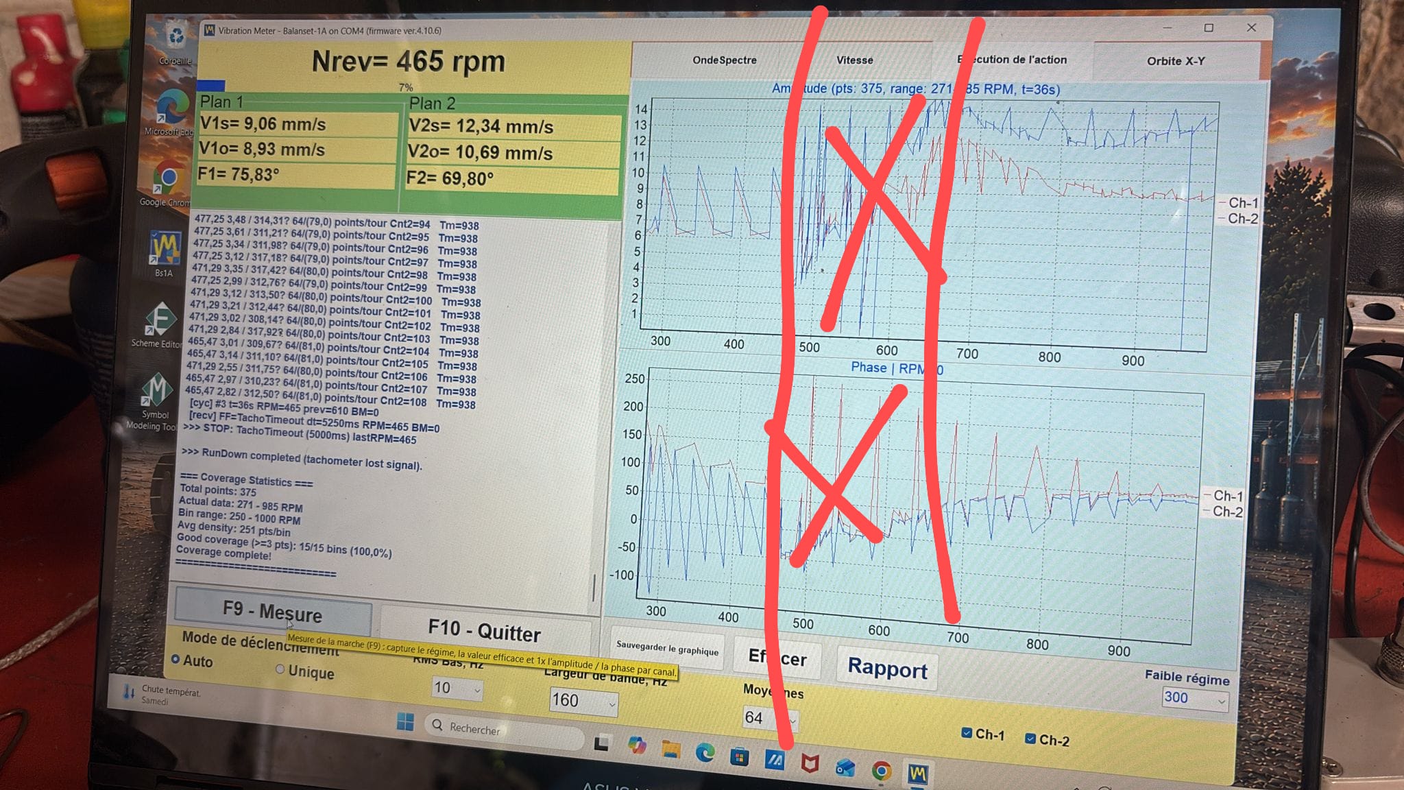
RunDown lors du travail sur le terrain. - Tous les essais d'une même série doivent être au même régime.
Choisir la masse d'essai
La masse d'essai doit modifier la vibration, sinon l'appareil n'a rien à partir de quoi calculer. Le critère : un changement d'amplitude de 20–30 % ou un changement de phase de 20–30° après l'installation de la masse d'essai.
Repères de terrain :
- tondeuses, broyeurs légers : 200–300 g ;
- gros broyeurs forestiers : 500–700 g ;
- un rotor de ~600 kg : 400–600 g ;
- très gros rotors (tonnes) : en kilogrammes (un rotor de 1,7 t a nécessité ~1 kg).
La formule d'estimation donnée par le support technique (masse du rotor Mr en kg, rayon de montage Rp en m, RPM N) :
Mp ≈ Mr / (Rp × (N/100))² [kg]Le logiciel dispose aussi d'un calculateur de masse d'essai (vibromera.eu/content/trial-weight-calculator/). Avec une masse d'essai trop petite, le changement se noie dans le bruit (cas réel : 3–7 g sur une turbine n'ont presque rien changé ; 5 g ont fonctionné une fois le bruit de fond réduit) ; une masse trop grande pousse le système vers la non-linéarité.
Fixez solidement la masse : un collier, un boulon, un aimant à bas régime — mais de façon qu'elle ne puisse pas se détacher. Pesez-la sur la balance du kit.

