ഡൈനാമിക് ബാലൻസിംഗ് (ടു-പ്ലെയിൻ ബാലൻസിംഗ്) വിശദീകരണം







1. Definition: What is Dynamic Balancing?
ഡൈനാമിക് ബാലൻസിംഗ് is a procedure for correcting അസന്തുലനം in a rotor by making mass corrections in a minimum of രണ്ട് വേർതിരിച്ച പ്ലെയിനുകൾ along its length. It is used when correction in one plane is not enough, because the rotor can combine static (force) unbalance and കപ്പിൾ അസന്തുലിതാവസ്ഥ.
2. Static vs. Dynamic Unbalance: The Key Difference
To understand dynamic balancing, it’s important to distinguish between the two main forms of unbalance.
- Static unbalance: the rotor’s center of mass is offset from its axis of rotation. It behaves like a single “heavy spot” and can be corrected with one weight in one plane (സ്റ്റാറ്റിക് ബാലൻസിംഗ്, also called സിംഗിൾ-പ്ലെയിൻ ബാലൻസിംഗ്).
- ഡൈനാമിക് അസന്തുലനം: unbalance is distributed along the rotor so that correction in one plane is not enough. This condition is detected in rotation and requires corrections in two different planes. This occurs when a rotor has two equal heavy spots on opposite ends, positioned 180° apart. This condition is statically balanced (it won’t roll to a heavy spot when at rest), but when it rotates, the two heavy spots create a turning force, or “couple,” that causes the rotor to wobble end-over-end. Couple unbalance can *only* be detected when the rotor is spinning and can *only* be corrected by placing weights in two different planes to create an opposing couple.
3. Correction Planes and Sensor Placement
രണ്ട്-പ്ലെയിൻ ബാലൻസിംഗ് is based on three things:
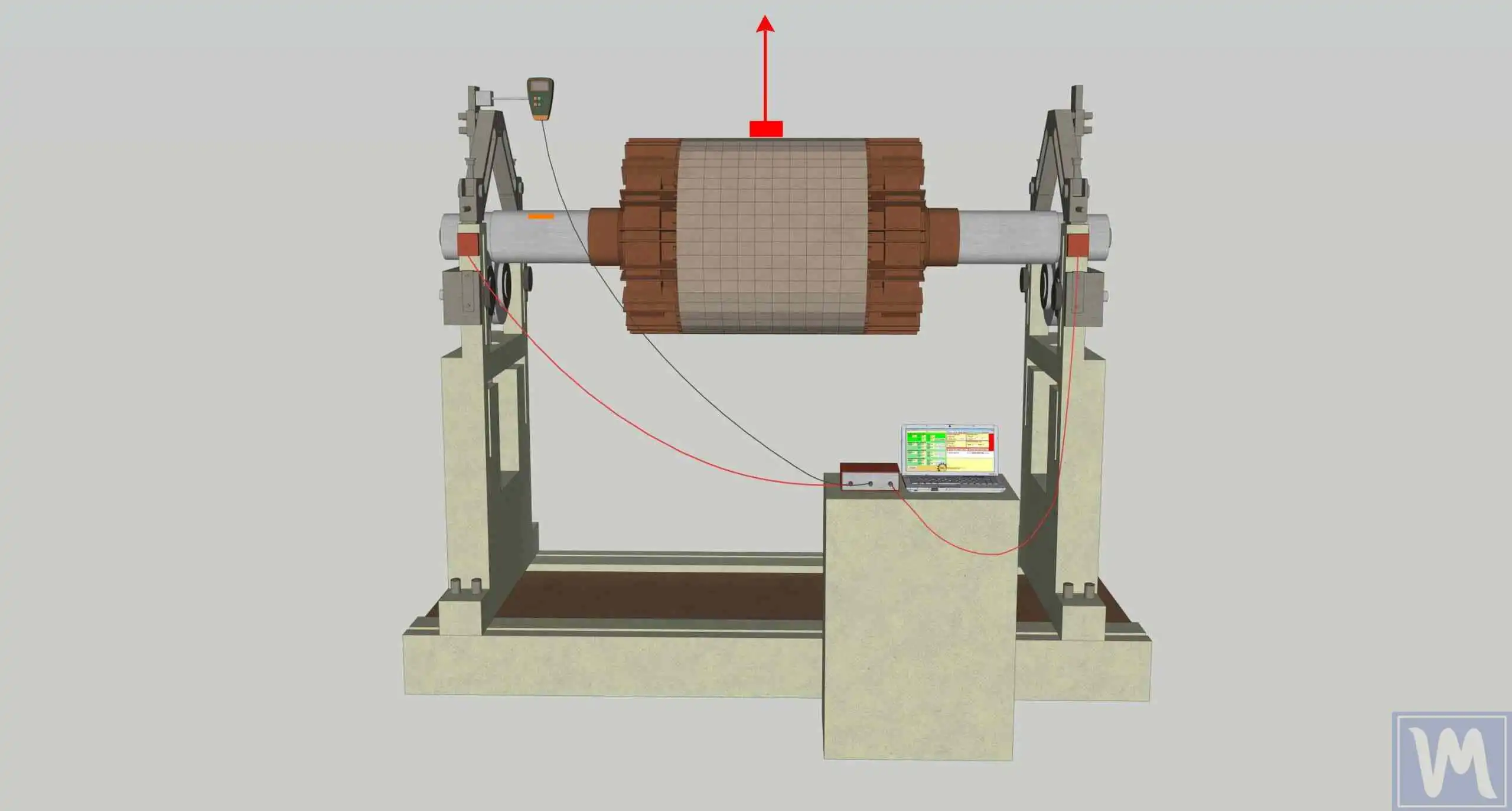
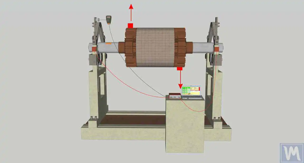
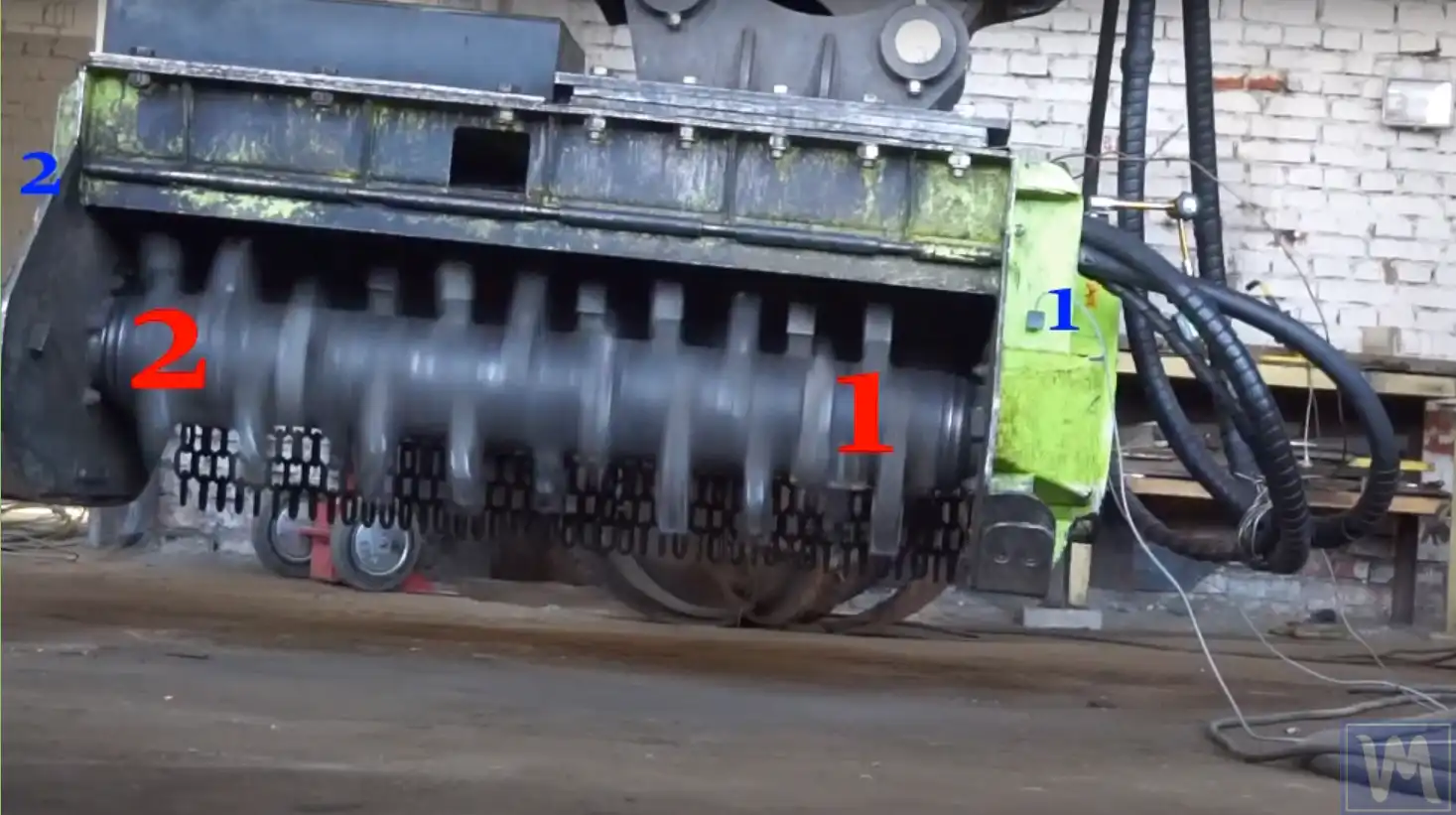
- Two തിരുത്തൽ പ്ലെയിനുകൾ (Plane 1 and Plane 2) where correction weights will be installed.
- Two vibration measurement points (typically near bearing housings) connected to two channels.
- A ഫേസ് reference (ടാക്കോമീറ്റർ + reflective mark) to measure speed and phase.
Below are typical examples showing correction planes and sensor placement for common rotor configurations.
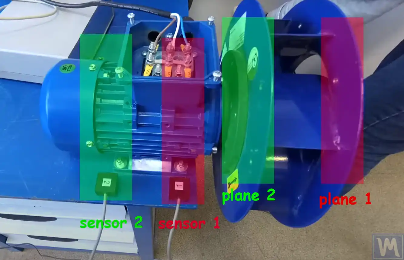
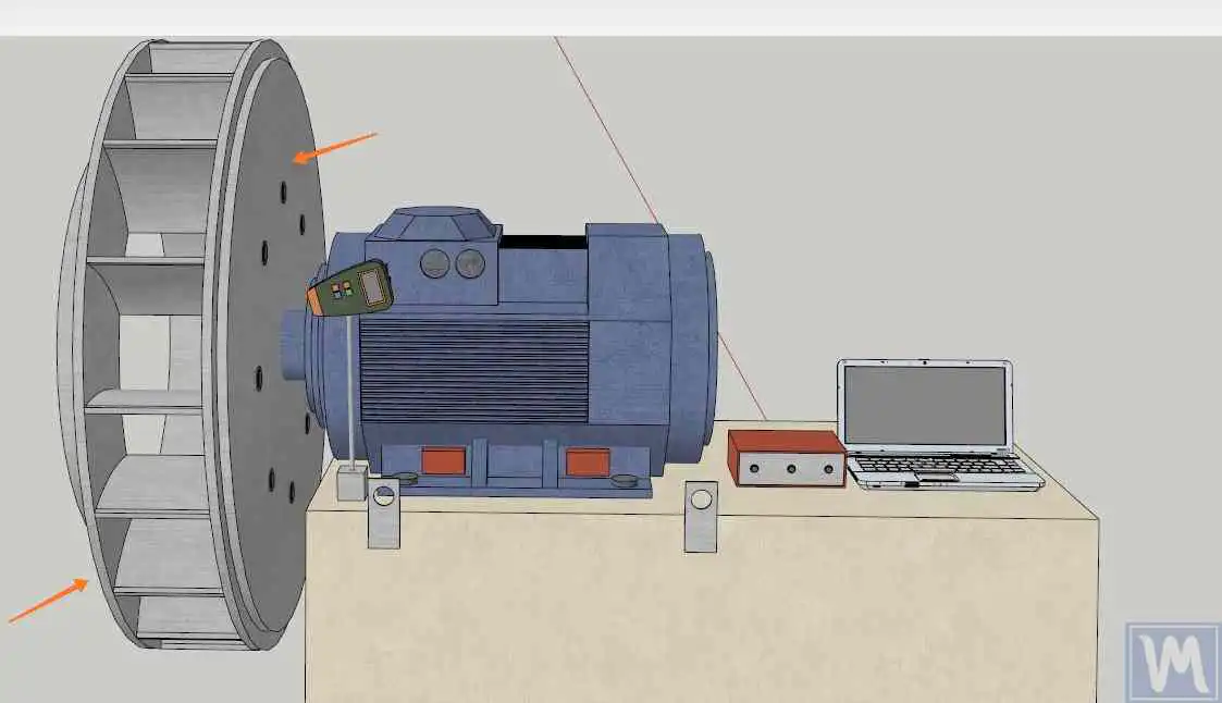
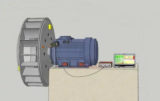
4. The Two-Plane Balancing Procedure
In the field, two-plane balancing is commonly performed using the ഇൻഫ്ലുവൻസ് കോഫിഷ്യന്റ് രീതി. The typical sequence is:
- Run #0: measure a baseline vibration (amplitude and phase) with no trial weights.
- Run #1: install a ട്രയൽ വെയ്റ്റ് in Plane 1, measure vibration again.
- Run #2: move the trial weight to Plane 2, measure vibration again.
- കണക്കാക്കൽ: the software calculates correction weights for Plane 1 and Plane 2.
- Correction and verification: remove the trial weight, install correction weights, and perform a verification run (trim run) to confirm the result.
When a calculated correction angle falls between two accessible fixing points, the required mass can be resolved onto the available positions with a two-plane correction-mass decomposition calculator, and the underlying single-plane sensitivity can be checked with an influence coefficient calculator.
5. Two-Plane Balancing with Balanset-1A
ബാലൻസെറ്റ്-1എ is a dual-channel, PC-based balancing system designed for single-plane and two-plane rotor balancing in field conditions and production environments. In two-plane mode, Balanset-1A measures rotor speed and the vector of 1x vibration (RMS and phase) on two channels and calculates correction weight parameters for both planes.
Because the ബാലൻസെറ്റ്-1എ is used directly on the installed machine, it balances under real operating conditions — alignment, bearing preload, and foundation effects all included — and reports the achieved ശേഷിക്കുന്ന അസന്തുലനം against the chosen tolerance, which can be cross-checked with a residual unbalance calculator (ISO 21940-11).
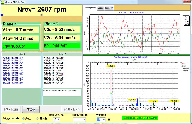
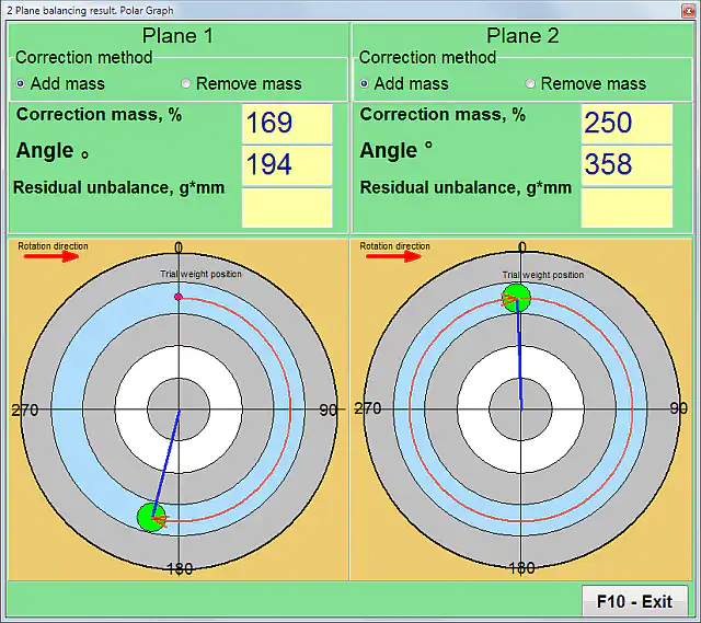
5.1 Software: dynamic balancing setup and result view
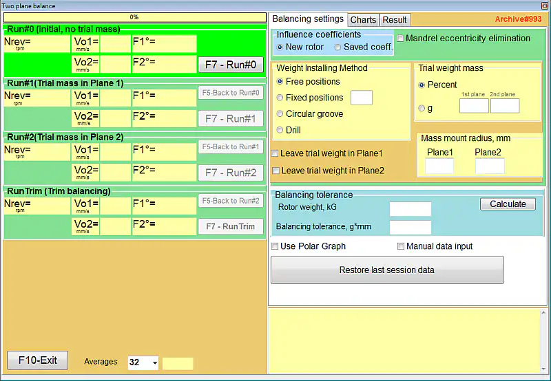
5.2 Vibrometer mode (quick check before balancing)
Before and during balancing, വൈബ്രോമീറ്റർ mode can be used to monitor vibration and confirm stable operation conditions for measurements.