Strona główna → Słowniczek → Wyważanie dynamiczne
Wyjaśnienie dynamicznego wyważania (wyważania dwupłaszczyznowego)
Praktyczny przewodnik po korekcji niewyważenia wirnika w dwóch płaszczyznach: kiedy jedna płaszczyzna nie wystarcza, jak działa metoda współczynników wpływu, jak liczyć kąt korekcji i jakie tolerancje osiągać. Oparty na doświadczeniu terenowym setek Balanset-1A użytkowników — od bębnów mulczerów po 24-tonowy wirnik.







1. Definicja: Co to jest równoważenie dynamiczne?
Wyważanie dynamiczne to procedura korygowania niewyważenie w wirniku poprzez wprowadzenie poprawek masy w minimalnej liczbie dwie oddzielne płaszczyzny wzdłuż jego długości. Jest używany, gdy korekta w jednej płaszczyźnie nie jest wystarczająca, ponieważ wirnik może łączyć niewyważenie statyczne (siłowe) oraz niewyważenie pary.
Przenośne przyrządy dwupłaszczyznowe, takie jak Vibromera Balanset-1A wykonują tę procedurę w terenie, mierząc drgania i faza na każdym łożysku i obliczając masy korekcyjne za pomocą metoda współczynnika wpływu.
Maszyny i sprzęt do wyważania dynamicznego
Praca w terenie wymaga przenośnej maszyny do wyważania dynamicznego zamiast stacjonarnego stojaka: Balanset-1A to przenośny dwukanałowy wyważarka dynamiczna z widmem FFT, korygująca niewyważenie w dwóch płaszczyznach na miejscu — we własnych łożyskach wirnika, z uwzględnieniem osiowania, wstępnego naciągu łożysk i wpływu fundamentu. Rozwiązany przykład znajdziecie w Wyważanie wału napędowego w terenie.
2. Niezrównoważenie statyczne i dynamiczne: Kluczowa różnica
Aby zrozumieć równoważenie dynamiczne, ważne jest rozróżnienie dwóch głównych form niewyważenia.
- Niewyważenie statyczne: środek masy wirnika jest przesunięty względem jego osi obrotu. Zachowuje się jak pojedynczy “ciężki punkt”: zatrzymany wirnik na swobodnych podporach sam obróci się ciężką stroną w dół. Można go skorygować jednym ciężarkiem w jednej płaszczyźnie (wyważanie statyczne, zwany również wyważanie jednopłaszczyznowe).
- Niewyważenie dynamiczne: miejsca ciężkie znajdują się na różnych końcach i po różnych stronach wirnika. W spoczynku taki wirnik może wyglądać na idealnie wyważony — po obróceniu wirnika o 90° oba miejsca ciężkie zdają się nawzajem równoważyć. Ale podczas obrotu każde miejsce ciężkie ciągnie w swoją stronę: obie masy tworzą siłę obrotową, czyli “parę”, która sprawia, że wirnik kołysze się z końca na koniec. Niewyważenie momentowe może tylko zostać wykryte podczas obrotu i może tylko skorygowane przez umieszczenie ciężarków w dwóch różnych płaszczyznach, tworzących przeciwdziałającą parę.
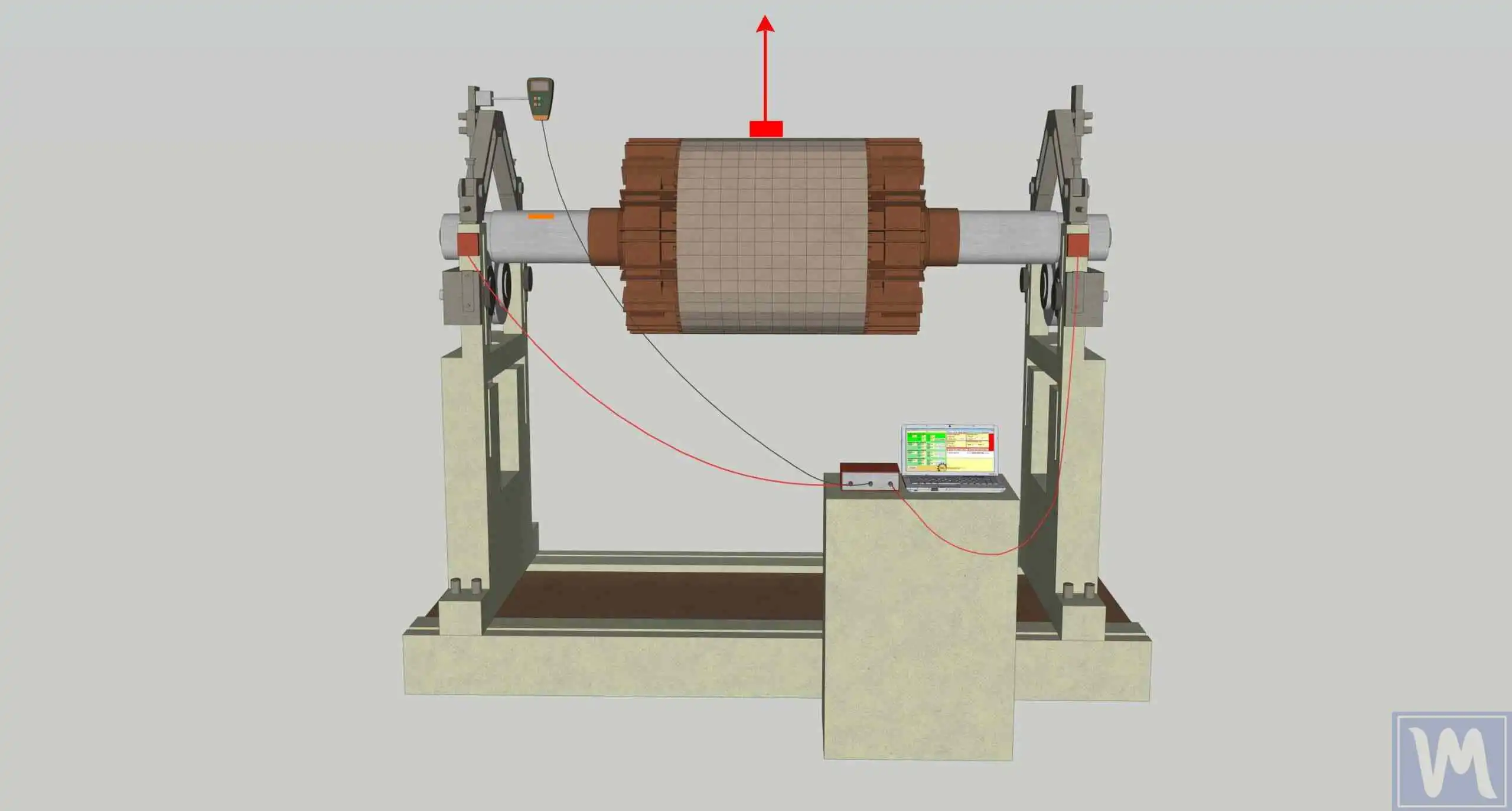
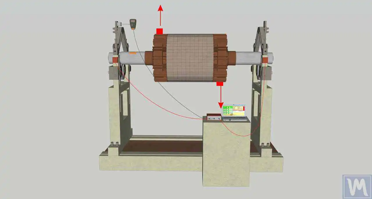
| Niewyważenie statyczne | Dynamiczne niewyważenie | |
|---|---|---|
| Wykrywalne w spoczynku? | Tak — wirnik toczy się ciężką stroną w dół na swobodnych podporach | Nie — ujawnia się tylko podczas obrotu |
| Zachowanie wirnika | Drga “w fazie” na obu podporach | Kołysanie: podpory drgają z różną fazą |
| Korekta | 1 ciężarek, 1 płaszczyzna | Ciężarki w 2 płaszczyznach, obliczane razem |
| Typowe wirniki | Wąskie tarcze, koła pasowe, wąskie wirniki wentylatorów | Bębny mulczerów, długie wały, wirniki kombajnów, wentylatory powyżej 3000 obr/min |
3. Jedna płaszczyzna czy dwie? Praktyczna reguła
Reguła praktyczna ISO 21940-11: jeśli wirnik szerokość jest mniejsza niż połowa jego średnicy (stosunek ~1:2; w praktyce terenowej wsparcie zaleca 1:3), zwykle wystarcza korekcja jednopłaszczyznowa. Długie wirniki wymagają dwóch płaszczyzn, ponieważ niewyważenie na obu końcach wirnika wzajemnie na siebie wpływają: ciężarek dodany w płaszczyźnie 1 zmienia drgania na obu podporach. Właśnie dlatego przyrząd dwupłaszczyznowy mierzy oba kanały jednocześnie (czujniki X1 i X2) i wyznacza obie masy korekcyjne naraz, zamiast traktować każdy koniec jako osobne zadanie jednopłaszczyznowe.
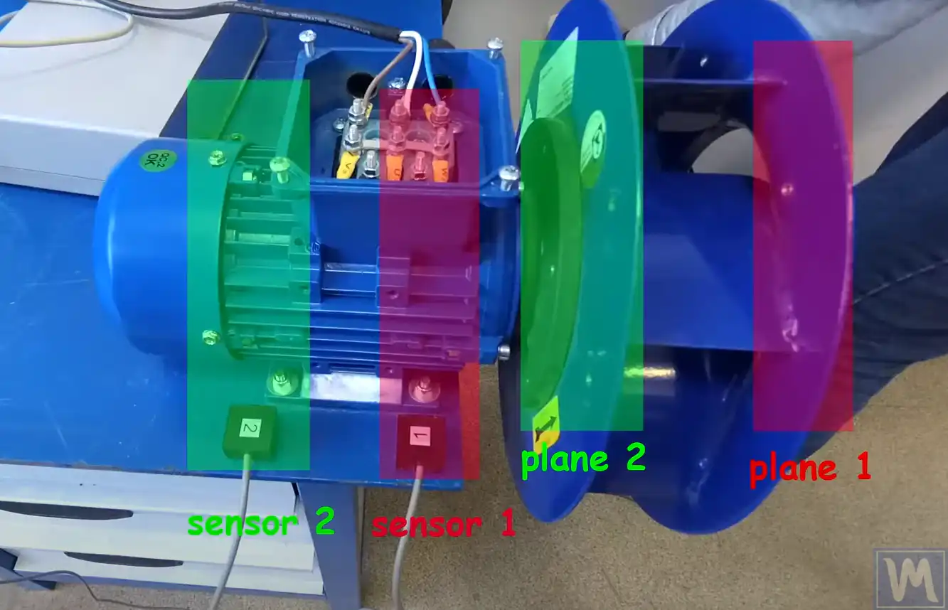
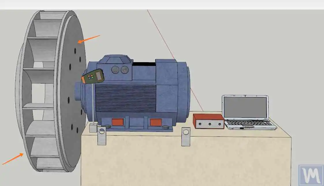
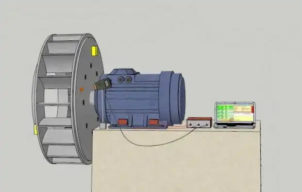
4. Płaszczyzny korekcji i rozmieszczenie czujników
Wyważanie dwupłaszczyznowe opiera się na trzech rzeczach:
- Dwa płaszczyzn korekcyjnych (płaszczyzna 1 i płaszczyzna 2), w których zostaną zamontowane ciężarki korekcyjne — możliwie najdalej od siebie wzdłuż wirnika.
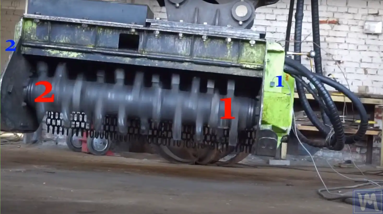
- Dwa punkty pomiaru drgań (zwykle obudowy łożysk) podłączonych do kanałów X1 i X2. Czujnik X1 odpowiada płaszczyźnie 1, czujnik X2 płaszczyźnie 2 — nie zamieniajcie ich w trakcie pracy.
- A faza odniesienie - tachometr skierowany na znak odblaskowy — aby zmierzyć prędkość i fazę. Jedno oznaczenie na obrót, naklejone na piaście lub wale (nie na łopatce), oraz nigdy nie przemieściło się między przebiegami.
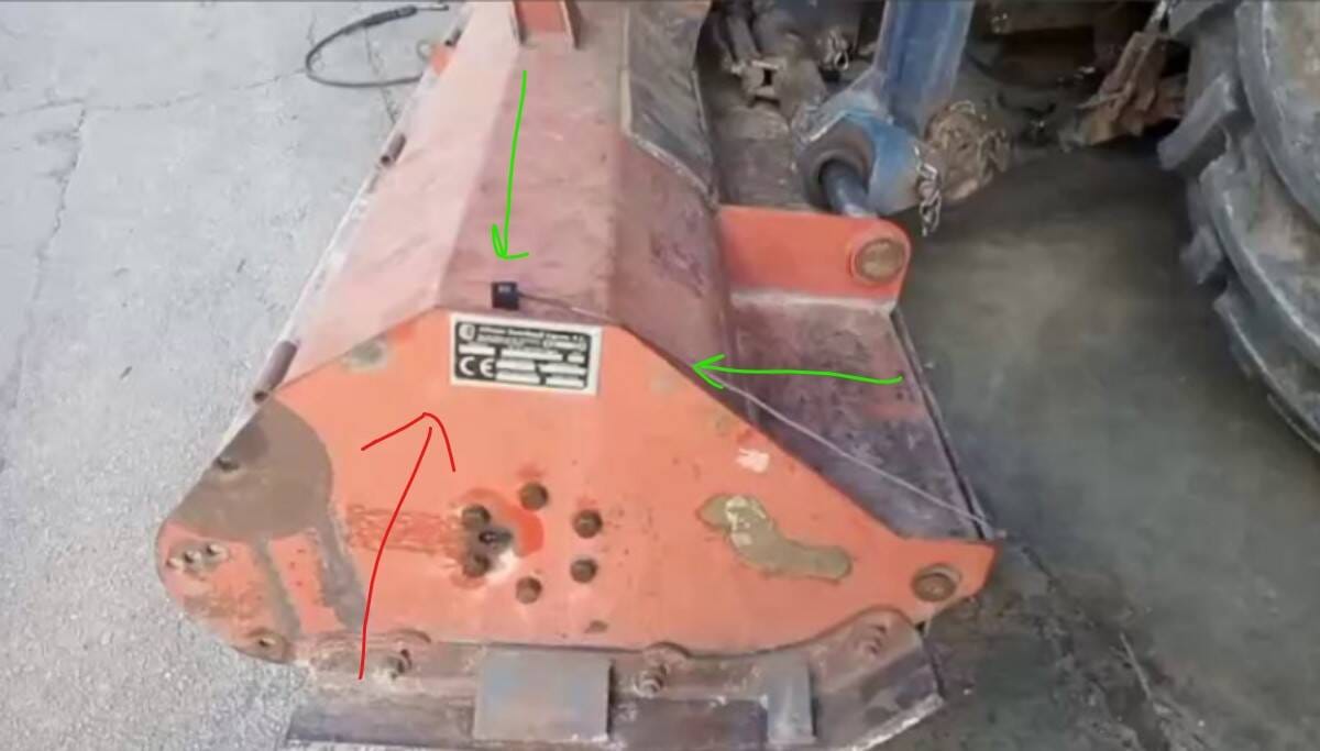
Typowe przykłady płaszczyzn korekcji i rozmieszczenia czujników dla typowych konfiguracji wirników:
5. Procedura wyważania dwupłaszczyznowego
Przed pierwszym przebiegiem upewnijcie się, że w ogóle jest co wyważać — i że pomiarom można zaufać:
- Brak luzu na łożyskach (paski zdjęte, poruszcie wirnikiem łomem), brak pęknięć, wszystkie mocowania dokręcone.
- Wirnik w konfiguracji roboczej: wszystkie łopatki/młotki/noże zamontowane, wirnik czysty.
- Czujniki w kierunku promieniowym na obudowach łożysk; znacznik tachometru na piaście; kable zabezpieczone z dala od wirnika.
- W Wibrometr : prędkość obrotowa odczytywana jest poprawnie i jest stabilna; amplituda powtarza się w granicach ~10–20%, a faza w granicach ~10–20° między przebiegami.
- Składowa 1× dominuje w widmie. Jeśli dominują harmoniczne 2× lub wyższe — najpierw usuńcie niewspółosiowość/luz.
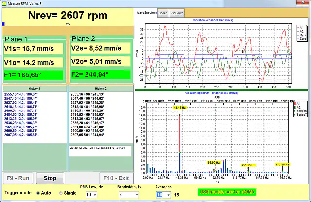
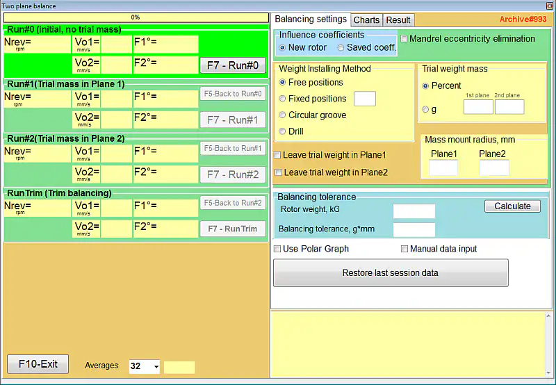
Terenowe wyważanie dwupłaszczyznowe wykorzystuje metoda współczynnika wpływu — urządzenie “uczy się” reakcji maszyny, mając znany ciężarek próbny:
-
Run #0 — wartość bazowa
Uruchomcie wirnik z wybraną prędkością wyważania bez ciężarków próbnych i zmierzcie drgania początkowe (amplitudę i fazę) na obu kanałach.
Zachowajcie tę samą prędkość obrotową dla każdego przebiegu serii — w granicach ~100 obr/min. Jeśli prędkość robocza znajduje się na rezonansie lub drgania przekraczają 40–50 mm/s, wyważajcie dwuetapowo, zaczynając od zredukowanej prędkości.
-
Run #1 — masa próbna w płaszczyźnie 1
Zatrzymajcie maszynę, zamontujcie masę próbną w płaszczyźnie 1 w oznaczonym miejscu, uruchomcie ponownie i zmierzcie. Masa próbna musi zmienić amplitudę lub fazę o co najmniej 20–30% — w przeciwnym razie przyrząd nie ma z czego liczyć (zwiększcie masę). Użyjcie Kalkulator masy próbnej dla wstępnego oszacowania.
-
Run #2 — masa próbna przeniesiona do płaszczyzny 2
Przenieście masę próbną z płaszczyzny 1 do płaszczyzny 2 (przeniesiona, a nie dodana dodatkowo!) i zmierzcie jeszcze raz.
-
Obliczenie
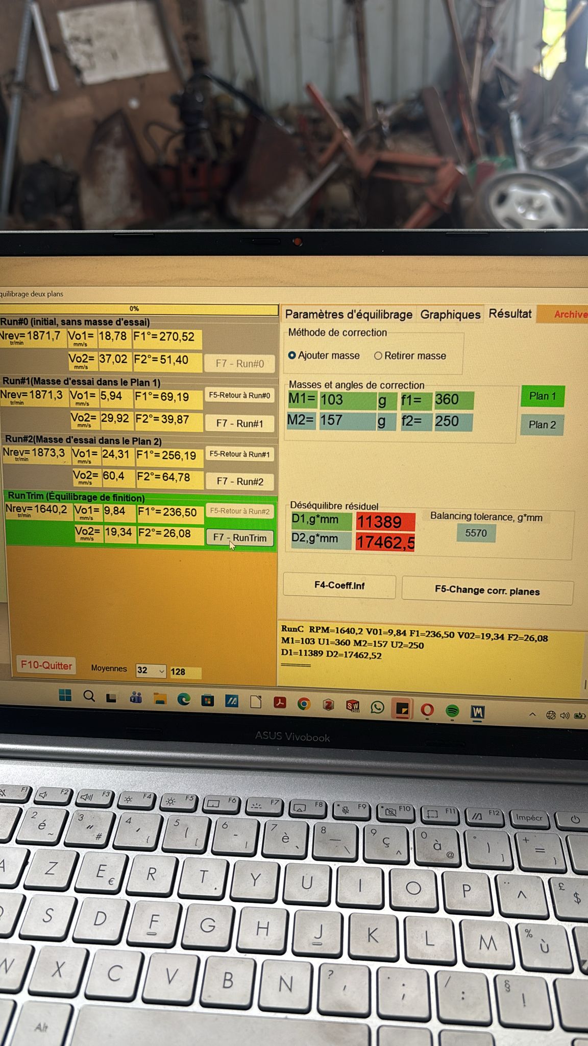
Oprogramowanie oblicza masę i kąt korekcji dla każdej płaszczyzny, rozwiązując obie płaszczyzny jednocześnie, tak aby uwzględnić wzajemny wpływ między końcami wirnika.
-
Korekta
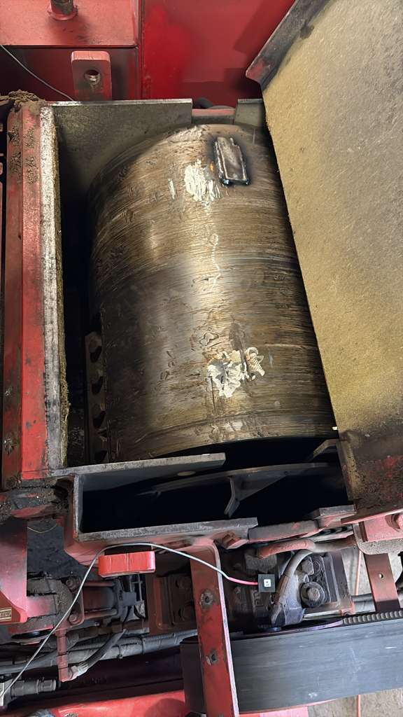
Usuńcie wszystkie masy próbne i zamontujcie masy korekcyjne na ten sam promień jako masę próbną. Spawanie jest standardem dla bębnów i wentylatorów (doliczcie ~100 g na sam spoinę); śruby, podkładki nitowe lub opaski zaciskowe też się sprawdzają, zależnie od wirnika.
-
Weryfikacja i wykończenie
Wykonajcie przebieg kontrolny (przebieg sprawdzający). Spadek drgań 3–10-krotny w ciągu 1–2 iteracji jest normalny dla mechanicznie sprawnej maszyny. Program oblicza niewielki ciężarek dodatkowy; powtarzajcie, aż zmieścicie się w tolerancji.
Gdy obliczony kąt korekcji wypada między dwoma dostępnymi punktami mocowania (łopatkami, otworami na śruby), wymaganą masę można rozłożyć na dostępne pozycje za pomocą dwupłaszczyznowy kalkulator rozkładu masy korekcyjnej, a leżącą u podstaw czułość jednopłaszczyznową można sprawdzić za pomocą kalkulator współczynnika wpływu.
6. Liczenie kąta korekcji — najważniejszy punkt ze wszystkich
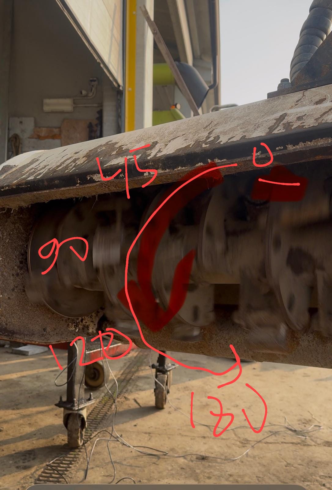
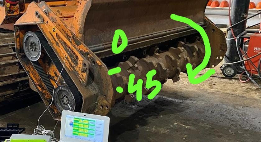
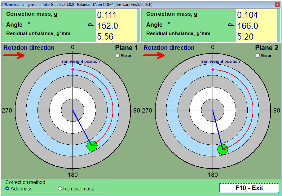
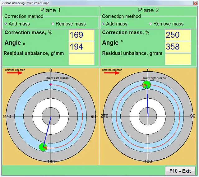
Kąt korekcji liczony jest od pozycji masy próbnej (0°), w kierunku obrotu wirnika. Nie przeciwnie do obrotu i nie od dowolnego punktu.
Przykład: ciężarek próbny znajdował się na “godzinie 12”, a wirnik obraca się zgodnie z ruchem wskazówek zegara, patrząc na niego. Obliczenia wskazują 90° → ciężarek korekcyjny trafia na “godzinę 3”. Klasyczny błąd to liczenie w kierunku przeciwnym do obrotu (montaż przy 360−70 = 290° zamiast 70°) — wtedy wibracja rośnie zamiast się zmniejszać.
Na wykresie biegunowym oprogramowanie pokazuje to wizualnie: różowa kropka to pozycja masy próbnej (0°), zielona kropka to miejsce, gdzie trafia masa korekcyjna, a czerwona strzałka wskazuje kierunek obrotu.
7. Wyniki i tolerancje: kiedy praca jest zakończona?
Dwa systemy oceny stosowane są równolegle — nie mylcie ich: mm/s (prędkość drgań zmontowanej maszyny, ISO 10816/20816) oraz g·mm (niewyważenie resztkowe samego wirnika, ISO 1940/21940-11). Przyrząd pokazuje obie wartości.
| Strefa | Prędkość drgań (RMS) | Ocena |
|---|---|---|
| A | do 1,4 mm/s | Doskonały — jak nowa maszyna |
| B | 1,4 – 2,8 mm/s | Dobry — nadaje się do długotrwałej pracy |
| C | 2,8 – 4,5 mm/s | Dopuszczalny przez ograniczony czas |
| D | powyżej 4,5 mm/s | Niedopuszczalny — wymagane działanie |
Korekty terenowe: dla maszyn rolniczych na miękkich podporach limity są łagodniejsze — nawet 7–8 mm/s to już dobry wynik dla mulczera; ściganie 0,5 mm/s tam nie ma sensu. Zwróćcie uwagę na składowa 1×, a nie tylko drgania ogólne: wyważanie redukuje właśnie tę część.
Niewyważenie resztkowe ocenia się wg klas G (G16 — wirniki rolnicze i wały kardana, G6.3 — wentylatory, bębny i wirniki ogólne, G2.5 — turbiny i obrabiarki, G1–G0.4 — wrzeciona). Dopuszczalną wartość g·mm na płaszczyznę dla masy, prędkości i klasy Waszego wirnika można sprawdzić za pomocą kalkulator niewyważenia resztkowego (ISO 21940-11) — ten sam kalkulator jest wbudowany w oprogramowanie Balanset-1A.
8. Jeśli drgania nie spadają
Szybka tabela diagnostyczna dla najczęstszych sytuacji “pogorszyło się / nie zbiega się”:
| Objaw | Prawdopodobna przyczyna | Co robić |
|---|---|---|
| Po zamontowaniu masy korekcyjnej drgania wzrosły zamiast się zmniejszyć | Kąt korekcji naniesiono w złym kierunku — przeciwnie do obrotu wirnika zamiast zgodnie z nim | Wyznaczcie kąt ponownie: zacznijcie od pozycji masy próbnej (0°) i liczcie w kierunku obrotu wirnika |
| Z każdym nowym przebiegiem program prosi o dodawanie coraz większej masy | Metoda korekcji w ustawieniach jest ustawiona na “usuń masę”, podczas gdy w rzeczywistości dodawane są ciężarki, więc znak wyniku jest odwrócony | Otwórzcie ustawienia wyważania i przełączcie metodę korekcji na “dodaj masę” |
| Niewielka zmiana prędkości (50–100 obr/min) zmienia poziom drgań kilkukrotnie | Prędkość wyważania znajduje się na rezonansie konstrukcyjnym lub blisko niego | Zarejestrujcie wykres RunDown (wybieg swobodny) i wybierzcie prędkość wyważania poza strefami rezonansowymi |
| Odpowiedź na zamontowane ciężarki nie jest proporcjonalna; wyniki skaczą z iteracji na iterację | Maszyna zachowuje się nieliniowo (miękkie podpory, zużyta lub uszkodzona konstrukcja) | Montujcie połowę — lub jedną trzecią — obliczonej masy na iterację i powtarzajcie przebieg kontrolny |
| Amplituda i faza są różne przy każdym przebiegu, mimo że nic nie zmieniono | Usterki mechaniczne (luz na łożyskach, pęknięcia, poluzowane śruby) lub błędne wyzwalanie tachometru | Najpierw napraw mechanikę; upewnijcie się, że tylko jeden znacznik odbija wiązkę tachometru |
| Program pokazuje prędkość 2–3 razy wyższą niż rzeczywista | Tachometr widzi dodatkowe odbicia: otwory kół pasowych, błyszczące miejsca, krawędzie łopatek | Przenieście znacznik odblaskowy na piastę lub wał; zakryjcie lub zmatujcie pozostałe powierzchnie odblaskowe |
| W widmie FFT prążek 2× (lub seria prążków 3×, 5×, 6×) jest wyższy niż prążek 1× | Niewspółosiowość wału lub luz mechaniczny — to nie jest niewyważenie | Najpierw napraw sprzęgła, pasowania i mocowania, a wyważajcie dopiero potem |
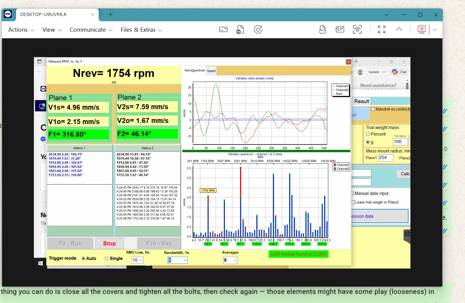
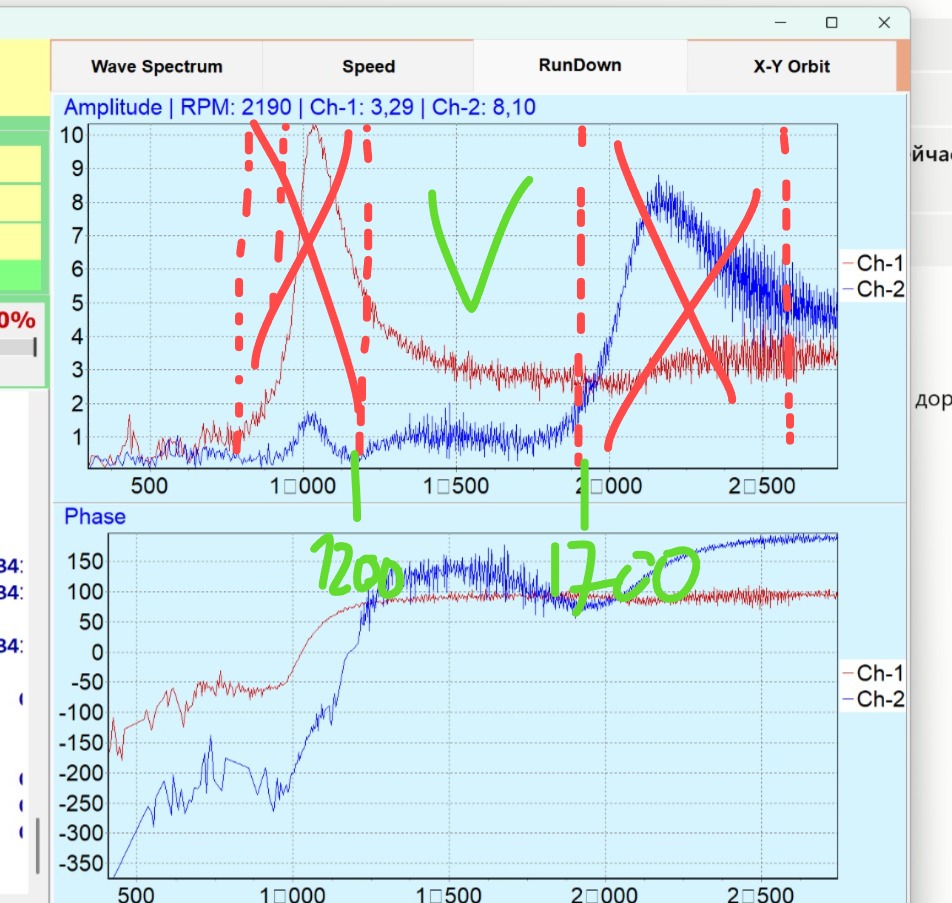
Pełne drzewo diagnostyczne — odczyt widma, poszukiwanie rezonansów, rzeczywiste przyczyny ze zgłoszeń wsparcia — znajduje się w bazie wiedzy: Drgania nie spadają: szukanie prawdziwej przyczyny.
9. Wyważanie dwupłaszczyznowe z Balanset-1A
Balanset-1A to dwukanałowy system wyważania oparty na PC, przeznaczony do wyważania wirników w jednej lub dwóch płaszczyznach zarówno w terenie, jak i w produkcji. W trybie dwupłaszczyznowym mierzy prędkość wirnika i wektor 1× wibracja (wartość skuteczną i fazę) na obu kanałach jednocześnie i oblicza parametry ciężarków korekcyjnych dla obu płaszczyzn naraz — łącznie z wykresem biegunowym, dziennikiem przebiegów i osiągniętym niewyważeniem resztkowym w odniesieniu do wybranej tolerancji ISO.
| Parametr | Balanset-1A |
|---|---|
| Kanały | 2 kanały drgań + kanał tachometru laserowego |
| Prędkość drgań (RMS) | 0,02 – 80 mm/s |
| Zakres częstotliwości | 5 – 1000 Hz |
| Zakres prędkości | 100 – 100,000 rpm |
| Dokładność fazowa | ±1° |
| Płaszczyzny wyważania | 1 lub 2 |
| Masa wirnika | Nieograniczony metodą (rzeczywisty rekord — wirnik 24 000 kg) |
| Wymagania dotyczące PC | Windows 7/8/10/11, USB; dowolny laptop biurowy |
| Oprogramowanie | Jednorazowy zakup, darmowe aktualizacje, brak subskrypcji |
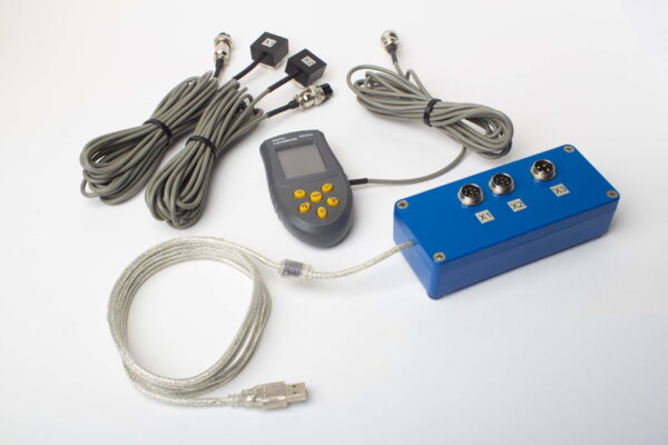
Oprogramowanie: konfiguracja dwupłaszczyznowa i widok wyników
Wyważajcie wirniki samodzielnie — na miejscu, we własnych łożyskach
Balanset-1A Zestaw pełny — €1,975, wszystko w komplecie: jednostka pomiarowa, 2 czujniki, tachometr laserowy, statyw magnetyczny, waga, oprogramowanie z darmowymi aktualizacjami dożywotnio. Używany na całym świecie przy mulczerach, wentylatorach, kruszarkach, wałach kardana i wrzecionach — z darmowym wsparciem e-mail opartym na setkach realnych zleceń wyważania.
10. Wideo: Balanset-1A w akcji
Krótki przegląd wyważania terenowego przy użyciu Balanset-1A — od montażu czujników po przebieg wykończeniowy. Więcej filmów, w tym przykłady dla konkretnych maszyn, znajdziecie na Kanał YouTube Vibromera.
11. Najczęściej zadawane pytania
Czy muszę znać masę wirnika, żeby go wyważyć?
Nie. Obliczenie masy korekcyjnej wymaga jedynie masy próbnej i jej promienia montażu. Masa wirnika jest używana wyłącznie do oszacowania masy próbnej oraz w kalkulatorze tolerancji ISO 1940 (klasa G).
Jaki jest maksymalny rozmiar lub masa wirnika dla wyważania dwupłaszczyznowego?
Metoda współczynników wpływu nie ogranicza masy wirnika — przyrząd mierzy odpowiedź podpór, a nie sam wirnik. Rzeczywisty rekord z Balanset-1A to wirnik defibratora cukrowni o masie 24 000 kg, wyważony do 0,47 mm/s.
W jakim zakresie prędkości pracuje?
Prędkość mierzy się od 100 rpm; praktyczny zakres wyważania zaczyna się od około 300 rpm. Górny zakres sięga dziesiątek tysięcy rpm — szybkoobrotowe wrzeciona wyważa się do klas G1–G0.4.
Czy mogę wyważyć wirnik bez wyjmowania go z maszyny?
Tak — to główny cel dynamicznego wyważania terenowego: wirnik wyważa się we własnych łożyskach, w rzeczywistych warunkach pracy. Pomiary zajmują zwykle 15–30 minut plus czas montażu ciężarków.
Skąd wiedzieć, czy jedna płaszczyzna wystarczy?
Reguła praktyczna (ISO 21940-11): jeśli szerokość wirnika jest mniejsza niż połowa jego średnicy (w praktyce — jedna trzecia), zwykle wystarcza jedna płaszczyzna. Długie wirniki — bębny, wały, szerokie wirniki wentylatorów — wymagają dwóch płaszczyzn, ponieważ oba końce wzajemnie na siebie wpływają.
Dlaczego drgania wzrosły po zamontowaniu obliczonego ciężarka?
Cztery typowe przyczyny: kąt korekcji naniesiono przeciwnie do kierunku obrotu wirnika; metoda korekcji w ustawieniach była ustawiona na “usuń masę”, podczas gdy w rzeczywistości dodawano ciężarki; prędkość wyważania jest bliska rezonansu; albo cała obliczona masa została zamontowana na maszynie nieliniowej (najpierw zamontuj połowę). Jeśli żadna z tych przyczyn nie pasuje, szukaj usterki mechanicznej: luzu na łożyskach, pęknięć, poluzowanych elementów.
Czy jest subskrypcja oprogramowania lub coroczna kalibracja?
Nie. Oprogramowanie Balanset-1A to jednorazowy zakup z darmowymi aktualizacjami i nieograniczoną liczbą instalacji, a przyrząd nie wymaga corocznej kalibracji — fabryczne współczynniki kalibracji dostarczane są z każdym zestawem.
Czy wyważa wały kardana (napędowe)?
Tak — zwykły wał kardana wyważa się w dwóch płaszczyznach; obciążniki wygodnie mocować opaskami zaciskowymi zabezpieczonymi klejem do gwintów (0.5 mm/s wyniku końcowego w rzeczywistym przypadku). Dla wałów z podporami pośrednimi wymagających 3–4 płaszczyzn należy użyć Balanset-4. Zużyty przegub krzyżakowy trzeba najpierw wymienić — wyważanie nie usuwa luzu.

