Balanset-1A · Vibromera · field balancing of rotors
Field Balancing with Balanset-1A, Step by Step: The Complete Guide
An expanded version of the quick guide. It adds what the short instructions leave out: the techniques and rules Nikolai explains to customers again and again in his chats (≈650 support conversations), plus the exact procedures from the official software manual (both editions — 2.2.x and 2.3.x). Written to be as thorough and as plain-spoken as possible: you can read the guide straight through like a textbook, or dip into it by section like a reference.
The half rule
Error-free angle reference
~40 problems with solutions
Máquinas típicas
ISO 1940 · ISO 10816/20816
The Essentials — Eight Rules That Decide Everything
If you remember only these, most balancing jobs will succeed
In Nikolai’s experience, 50–90% of “it won’t balance” cases are bearings, cracks, or resonance — not unbalance. Remove the belts, rock the shaft with a pry bar in two directions, inspect the welds, tighten the bolts. The slightest bearing play rules balancing out entirely.
Never install the full mass the instrument calculated in one go. Install half (a third on a nearly balanced rotor), do a trim run, and watch the response. A real machine is nonlinear — the full mass often overcompensates and flips the angle by 180°.
The correction weight angle is measured from the spot where that plane’s trial weight was installed, in the direction of rotor rotation. Not from the reflective mark! This is the number one beginner mistake. Each plane has its own zero.
A valid trial run changes the 1× amplitude by 20–30% or the phase by 20–30°. Any less, and the instrument has nothing to work from — the calculation will be garbage: increase the weight and repeat. More than a twofold change is also bad.
Before balancing, open the Vibration Meter (F5) and watch: the amplitude and phase must repeat (scatter up to 10–15%, phase up to 10°). “Wandering” readings are a sign of resonance or a mechanical problem: do not balance.
A sharp jump in vibration when the speed changes by 100–200 rpm, a phase flip of ~180°, correction weights going “round in circles” — that is resonance. Find it with a run-down plot or a bump test, and balance on the flat “plateau” of the curve with a 20–30% speed margin.
Speed, the positions of the sensors, tachometer, and mark, belt tension — everything must be identical in every run. If anything at all has changed (even the stiffness after welding), start the procedure over from Run 0 and the trial weights.
Trim iterations never end — the instrument will always suggest one more small weight. Benchmarks: below ~5 mm/s is a good field result; below 2 mm/s, a coin stands on its edge. A healthy machine balances in 4–5 runs; if you have done many runs with no result, look for a mechanical cause.
How to use this guide. If this is your first balancing job, read the sections in order — it takes about an hour and saves a day in the field. If you already work with the instrument, keep the “Troubleshooting” y “Machines” sections and the checklists handy. Checklist ticks persist when you close and reopen the file.
How It Works — Theory in Plain Terms
Five minutes of theory that explain every “oddity” of the procedure
What unbalance is
An ideal rotor has its mass distributed evenly, and its center of gravity lies exactly on the axis of rotation. A real rotor always has a “heavy spot”: weld build-up, wear, caked-on dirt, manufacturing inaccuracy. As the rotor spins, this extra mass pulls it toward its own side — once per revolution. The result is vibration exactly at the rotational frequency: it is called the componente 1× (“one-x”), or once-per-revolution vibration. The job of balancing is to add (or remove) a weight so that it compensates for the heavy spot.
n — speed, rpm. Example: 1,500 rpm → 1× = 25 Hz. The force from unbalance grows with the cuadrado of speed: at 3,000 rpm the same heavy spot shakes four times harder than at 1,500.
Three numbers on the screen: V1s, V1o, and F1
| Lectura | Qué es | What it is for |
|---|---|---|
| V1s / V2s — overall vibration | The total vibration level (RMS) across the whole frequency band, mm/s. It includes everything at once: unbalance, bearings, misalignment, belts, interference. | Assess the overall condition of the machine and compare it with ISO 10816/20816 limits. |
| V1o / V2o — 1× component | Vibration strictly at the rotor’s rotational frequency, mm/s. This is exactly what unbalance produces. | The key balancing parameter: the instrument calculates the weights from the 1× amplitude and phase. |
| F1 / F2 — 1× phase | The angle of the vibration vector relative to the reflective mark seen by the tachometer. | Tells you donde the heavy spot is pulling, not just con qué fuerza. |
The key quick test: compare Vo with Vs. The 1× component physically cannot be larger than the overall vibration. If Vo ≈ Vs, almost all of the vibration is coming from unbalance, and balancing will help. If Vo is noticeably smaller than Vs (for example, V1s = 12 mm/s but V1o = 1 mm/s), it is not the rotor that is shaking: the energy sits in harmonics and noise (bearings, misalignment, play), and balancing is pointless until the real cause is found. Check the spectrum.
The influence coefficient method — why a trial weight is needed
The instrument knows nothing about your machine: neither the rotor mass, nor the stiffness of the bearing supports, nor the effect of the belts and frame. So it is impossible to calculate a weight from the initial vibration alone. The procedure is built as a “question to the machine”:
- Run 0 — measure the initial vibration vector (amplitude and phase) with no weights.
- Run 1 — install a peso de prueba of known mass at a known location and measure how the vector changed. This is the “question”: the system answers how sensitive it is to the weight and which way the phase shifts. The answer is called the coeficiente de influencia.
- The rest is arithmetic: knowing the response to a known weight, the instrument calculates what weight, and at what angle, will fully compensate the initial vector.
Why it doesn’t work “in one shot” — nonlinearity
The instrument’s calculation assumes the system is linear: add twice the mass, and the vibration changes twice as much. A real machine is nonlinear: play, support compliance, friction, aerodynamics. To put it plainly, in Nikolai’s words: you add 100 g and the vibration rises by 10 mm/s; you add another 100 g and by the calculation it should be +20, but it comes out +34 or +14. The instrument draws a straight line, but reality is a curve.
Two practical consequences follow:
- The “half rule”: install 1/2 of the calculated mass and check with a trim run. If it dropped by exactly half, the system is linear — go ahead and add the rest. If it “drifted”, move in fractional steps (details in the “Balancing” section).
- Balancing is an iterative process, not a single precise shot. Two or three trim runs are normal, not a sign that something went wrong.
Two standards — cause and effect
Balancing involves two different sets of quantities, and they are constantly confused:
- g·mm and G grades (ISO 1940 / ISO 21940-11) — la causa: how much excess mass sits in the rotor itself, and at what radius. This is a property of the rotor, independent of where it is installed.
- mm/s (ISO 10816 / ISO 20816) — la efecto: how hard the machine shakes. It depends on the supports, foundation, and resonances.
In the field you work in mm/s; g·mm is needed on balancing machines and when a standard requires a report with a G grade. The software has an ISO 1940 tolerance calculator — see the “Trim Runs and Evaluating the Result” .
Preparation: Safety and Mechanics
Half an hour of inspection saves a day of balancing
Seguridad
Before mounting sensors or weights, stop the machine and make sure it cannot start accidentally. Anything done by hand is done only on a machine that is not moving.
- Do not stand in the rotor’s plane of rotation during runs — a weight that comes loose flies exactly there. Above 2,000 rpm, move the table with the laptop out of the way too.
- Attach weights so they are guaranteed not to come off at operating speed: “a weight that flies off is a real projectile.” Magnets used as weights always fly off at operating speed.
- Standard guards on the rotor and belt drives stay in place; keep tools away from rotating parts.
- Do not balance a rotor with cracks, damaged blades, or visible runout — repair it first.
- Do not run at a speed where the machine behaves unstably or goes into resonance.
- Do not place the tachometer near a fan’s intake airflow — there have been cases where it got sucked into the impeller.
Machine inspection: the diagnostic sequence
Balancing removes only unbalance. Everything else — cracks, bearing play, loose fasteners, misalignment, resonance — it does not fix — and often masks. A proven search order: 1) bearings → 2) cracks → 3) bolts → 4) resonance.
Inspection checklist for a stopped machine
0 / 10
Diagnosing “by ear and by hand” — worth learning
- Listen to the machine. Walk along the components during run-up and run-down: clanking, knocking, or rustling will point to the problem component more precisely than any instrument. On run-down, catch the moment the sound disappears.
- By hand, check every fastening and cover — whatever rattles is what is loose.
- Electrical or mechanical? Cut the power while running: electromagnetic vibration disappears instantly, mechanical vibration fades gradually along with the speed. Peaks at 50/100 Hz (or 300 Hz with a VFD) are electrical, not unbalance.
- Two rotors on one frame running at the same speed cannot be balanced at the same time — the instrument cannot separate their contributions. Remove the belts and work on one at a time.
- Vibration grows farther from the rotor (a ladder, cab, or mirror shakes while the bearing supports are calm) — that is resonance of a loose structural element, not unbalance: put the sensor right on the shaking element and find its frequency.
Device, Connection, and Software
Channels, tachometer, firmware, settings — everything you need before the first measurement
Kit contents and channels
- Balanset-1A: USB unit, two sensores de vibración (accelerometers), tacómetro láser, cinta reflectante, soporte magnético, scale, carrying case. The whole kit is powered from the laptop’s USB port — no batteries at all.
- Sensor 1 → connector Ch-1 (X1 on older housings) → plane 1; sensor 2 → Ch-2 (X2) → plane 2. Single-plane balancing uses channel 1. The tachometer goes into the Tacho connector (X3). Each channel is calibrated individually — do not mix them up.
- Channel colors are the same throughout the software: Ch-1 — dark red, Ch-2 — blue, tachometer — purple.
The tachometer takes three presses to turn on
ON → AUTO → LASER. Without LASER pressed, the beam is dim and the mark is read with dropouts. There are no batteries in the tachometer — it is powered through the cable; do not open the battery compartment cover and do not open the housing. With the rotor spinning, the tachometer display should show the speed in rpm.
Connecting to the computer
- Connect the sensors and the tachometer to the unit, and the unit to the computer’s USB port. The order is not strict: the software finds the device on its own at any time.
- Start the software and wait for the green status line at the bottom of the main window: USB module found on COMx. The device shows up in the system as an “Arduino Due” COM port.
- A blinking yellow line means the device has not been found (it is still searching); orange means the cable is unplugged or the port is taken by another program. Clicking the status line itself triggers an immediate reconnection attempt.
- If the cable gets pulled out during a session, just plug it back in: the connection and the live data stream recover on their own, but an interrupted measurement has to be repeated.
Software: versions and the two “eras” of the interface
- The 1.71/1.72 line — the old classic. As of today, we recommend updating to 2.x: a stable release is already out, and it has run-down plots.
- The 2.x line — a rewritten core: continuous data stream, run-down (coast-down) plot, bump test, orbits, adaptive measurement, auto-updates, session recovery. Current 2.3.x versions require device firmware 5.5.0+ — with older firmware, measurements are blocked and the software itself offers to update it (15–30 seconds, do not disconnect the cable).
- Caution: the hotkeys differ between generations! In the new edition: F6 — Balancing, F7 — Charts, F8 — Reports. In the old one: F6 — Reports, F7 — Balancing, F8 — Charts. Go by the button labels — the key is always printed right on the button.
- There are two balancing forms — Classic (separate windows for 1 and 2 planes) and Moderno (a single window with run cards and a live signal). Select it under F4 – Settings → Balancing form. The math is the same — use whichever is more convenient.
Calibration coefficients — don’t lose them!
Every device has its own individual channel calibration coefficients (usually numbers in the 16–25 range). They are duplicated on the label on the bottom of the device and on the box, and in a file on the USB flash drive from the kit. When reinstalling or updating older software versions, they must be carried over (the F4 – Settings → Vibration sensitivity tab); in the new 5.x firmware they are stored in the device itself and survive updates. The coefficients only affect the absolute mm/s readings — the balancing itself will converge even with inaccurate ones, but the assessment against the vibration limits will be off.
Small things that save the day in the field
- Session recovery. The software autosaves every balancing step. After a crash or an accidental close, answer “Yes” to the recovery prompt and all runs come back. The Menu → Restore Session button also works manually. Careful: Nuevo rotor deletes the saved session permanently.
- COM port error / PurgeComm Error 22 after Windows 11 updates is a known widespread problem: update the software to version 2.x (the bug is fixed only there), unplug and replug the cable, and restore the session if needed.
- Instalación: use the setup wizard without deselecting the database components and drivers; Windows will ask for a restart — do not agree until the installation is complete; do not put the program folder in OneDrive; get past the SmartScreen block via “More info → Run anyway”.
- Interference from the VFD (variable frequency drive): ferrite rings on the cables (first of all on the output cables to the motor), tightened coupling nuts on the sensor connectors (the shield runs through them — a loose nut gives 50 Hz pickup), and run the laptop on battery power. The VFD itself is useful, though: it is a convenient way to change the rpm smoothly and move away from resonance.
- F12 in any window saves a screenshot to the Documents\Bs1A\Screenshots folder: handy for the report and for questions to support. To send a report to support, use F1 – About → Report a problem… (attach the screenshots and the full log).
- Spares: the tachometer is the most fragile part, so carry a spare; the sensors are nearly indestructible; the weak spot is the cables and connectors.
Device specifications (brief)
| Velocidad de vibración (RMS) | 0.02–80 mm/s |
| Working frequency band | 5–550 Hz (FFT spectrum up to 1,000 Hz; above 550 Hz the readings are understated) |
| Velocidad | 100–100,000 rpm (in practice, balancing from ~100–300 up to 30,000–45,000 rpm) |
| Precisión de fase | ±1° |
| Sensores | MEMS accelerometers ±3g, potted in compound; cables 4–5 m (up to 10–15 m on request) |
| Tacómetro | laser, working distance 10–500 mm |
| Potencia | from the laptop’s USB port, the whole kit |
| OS | Windows 7–11 (no macOS/Android); the software has no licenses or subscriptions, updates are free |
One limitation, stated honestly: early-stage bearing diagnostics (envelope analysis, 10–50 kHz) is beyond this device — its frequency band is too narrow for that. Advanced bearing defects are visible in the spectrum.
Mounting the Vibration Sensors
Half of the machines that “won’t balance” are cured by mounting the sensors correctly
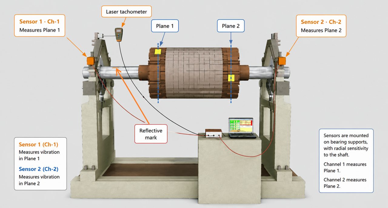
Where and how to mount
- Strictly radial — perpendicular to the axis of rotation; the measuring axis passes through the magnet. Never on the end face of the machine: that is axial vibration, and the balancing “won’t work.” Real case: a mulcher “would not balance” twice while the sensors sat on the end face; they were moved to the top — immediately 5 and 7 mm/s and quiet. “Sometimes it all comes down to the basics.”
- Only on a rigid, solid part, as close to the bearing as possible — the bearing support, the frame, next to stiffening ribs. Not on loose covers, not on sheet-metal guards, not on parts separated by a gasket or rubber. If the signal is “ragged,” does not look like a sine wave, or the overall vibration is far higher than the 1× component, the sensor is sitting on a part that is moving on its own — relocate it.
- On rigidly mounted machines (bedplate, foundation) the vertical stiffness is often so high that the signal is “drowned out” — mount the sensor horizontally: the machine is more compliant in that direction. On soft/spring supports, mount it on top. Changing the sensor orientation is a legitimate way to get away from resonance, but after that the whole procedure starts over.
- Contact only through the magnet, over its full face: the sides of the sensor must not touch the housing. Do not put a flat magnet on a cylindrical surface — the contact is only a single point, and the sensor rocks. There is an M4 thread under the magnet: in awkward spots, mount with a stud or an adapter; on aluminum housings (the magnet does not hold) use a long cable tie looped around or an M4 bolt.
- Not on the spring element of the balancing stand: the spring deforms and distorts the signal. The sensor goes on the moving part of the support, as close to the bearing as possible.
- Cables: never pull the sensor by its cable, and route the cables so they cannot get wound onto the rotor (this is the most common way a kit dies). Tighten the “bell” coupling nuts on the connectors: the shield runs through them, and a loose nut picks up 50 Hz mains interference.
- Welding with the sensors installed is allowed — leave the sensors alone, but disconnect the machine’s/tractor’s ground so the welding current does not flow through the electronics.
Quick check of sensors and channels
- Open the Vibration Meter and shake the sensor by hand: a sine wave with an amplitude of about 30–100 mm/s should appear on the chart. A steady 0.0X mm/s is the noise floor: the sensor, cable, or connector is dead.
- Localize the fault by swapping: swap the sensors at the instrument connectors, then at the machine. If the “zero” follows the sensor, the sensor/cable is at fault; if it stays on the channel, it is the connector or the instrument channel.
Tachometer and Reflective Mark
The mark is the phase reference: anything that disturbs it disturbs the calculation
Do not touch the tachometer or the mark for the entire procedure. The mark is the phase zero. If the tape is moved or the tachometer is shifted between runs, the instrument will take the shift for the effect of the trial weight and calculate the weights incorrectly. This is a real case: a customer repositioned the mark in the middle of the procedure and “broke” the calculation.
The Mark
- Uno mark on the circumference, 10–20 mm wide (wider at high speed: at 14,000+ rpm the tachometer misses a narrow mark). The white reflective tape from the kit works best.
- The background around the mark must be matte and dark. Blacken a shiny shaft with a black marker or cover it with matte tape, otherwise the tachometer will count glare as marks.
- Where to stick it: on the hub or the shaft — on a part that rotates strictly at the rotor speed. Not on a blade (otherwise the instrument will see all four blades). If the rotor is behind a gearbox, the mark goes on the rotor itself, not on the input shaft.
The Tachometer
- Switching on: ON → AUTO → LASER; distance to the mark 10–500 mm (usually 20–50 cm); if there is glare, tilt the beam about 45° to the surface.
- Speed reading 2–3 times higher than actual? The laser sees “extra marks”: shiny spots, bolts, holes, welds, oil stains. Diagnosis is simple: 8695 / 2856 ≈ 3, so there are three “marks.” Sand or cover the shiny spots, change the angle and distance.
- Sun and bright daylight blind the photocell — even without direct sun. Symptom: you walk up to the tachometer (blocking the light) and it works; you step away and it stops. Cure: shade it any way you can — a piece of cardboard, a hand, a rag, an umbrella. “Nothing works better than a simple piece of cardboard.”
- The “12 or 6 o’clock” trick: if the implement on the tractor’s hydraulics slowly sags, aim the beam at the top or bottom point of the circumference — as it sags, the laser simply stops seeing the mark (which is obvious) instead of shifting the phase unnoticed.
- “Tachometer failure” even though the speed reading is correct — the tachometer filter is too strict for a machine with “floating” speed (belt drive, agricultural machinery). Standard cure: set Tacho unevenness = 200 (older versions) or loosen the Tacho filter en F4 – Settings (newer versions: Auto / Fine 1% … Rough 20%). But if you can, remove the cause of the instability first instead of loosening the filter.
- Above ~45,000–60,000 rpm the tape starts coming off and itself introduces unbalance — switch to a Hall sensor (it connects to the instrument).
- Checking the tachometer without a machine: point it at a lit mains-powered incandescent lamp: a working unit reads about 6,000 rpm on 50 Hz mains or about 7,200 rpm on 60 Hz mains (the filament flickers at twice the mains frequency).
Before Balancing: Vibration Meter, Spectrum, Resonance
Three checks that decide whether balancing is possible at all
Check 1. A minute in the Vibration Meter: stability
- Open the Vibration Meter: F5 – Vibration Meter. Bring the machine up to operating speed.
- Watch for a minute. The readings must repeat: amplitude scatter within 10–15%, phase within 10°. In newer versions a colored bar under the values helps: green STABLE means you can measure, orange UNSTABLE means you cannot.
- If the readings “wander” more than that, it is too early to balance: the cause is resonance, unstable speed or a mechanical problem. The instrument will mistake random fluctuations for the effect of the trial weight, and the calculation will be garbage.
- If the readings are unstable, you can increase the averaging (Promedios: 32 by default, 64–128 when unstable), but remember: averaging hides the symptom rather than curing the cause.
Check 2. Vo versus Vs and the spectrum
Compare V1o with V1s (see the theory). If the 1× component is only a small part of the overall vibration, open the Analyzer (F7 – Charts, F8 in the old version) and look at the spectrum:
| What the spectrum shows | Qué significa |
|---|---|
| One dominant peak exactly at 1× | Unbalance is likely — after checking the mechanics, you can balance. |
| A pronounced peak at 2× | Misalignment, coupling, bent shaft, geometry. Balancing will not fix it. |
| A “forest” of harmonics: 2×, 3×, 4×… | Loose fasteners, play, parts touching. Tighten everything down and fix these first. |
| Peaks at 50/100 Hz (or 300 Hz with a VFD), not multiples of the running speed | Electrical/interference, not mechanical. Test: cut the power — electrical vibration disappears instantly. |
| A peak with a wide, “smeared” base | Unstable speed or a resonance nearby. |
| Peak stays put when the speed changes | Structural resonance. If the peak moves with the speed, it is a rotating element (pulley, belt, internal shaft): point the laser tachometer at the suspect component and compare the frequencies. |
Check 3. Resonance
Resonance is when the running speed coincides with a natural frequency of the structure. At resonance and near it (±20–30% of speed) balancing is impossible: the readings jump, the phase flips, and the instrument keeps asking for weights “all the way around” the rotor.
- Signs: vibration changes several-fold with a speed change of only 100–200 rpm (5 mm/s becomes 15 mm/s); the phase flips by ~180° as you pass through the peak; the structure reacts sharply to small things (a rag, a prop).
- Run-down (coast-down) plot is the main tool for finding it: Vibration Meter → Run-down tab → bring the rotor up to speed → F9 → switch off the drive and let it coast down freely. The program plots amplitude and phase versus speed: resonance = a peak plus a phase flip. Balance on a “plateau” well away from the peaks.
- Prueba de impacto (Bump test) is for machines that cannot be run up through resonance: with the machine stopped, enable the Prueba de impacto (Bump test) tab (checkbox in F4 – Settings → Experimental), press Start and strike with a rubber mallet (or a hammer through a wooden block — never bare steel) next to the sensor, not on it. The spectrum peaks are the natural frequencies; handy conversion: 1 Hz = 60 rpm.
- Stepped sweep: start from the minimum speed and go up in steps of 50–100 rpm, holding each step for half a minute and taking 3–4 measurements — a table of amplitude and phase will show the danger zones and the “valleys” where balancing is safe.
- How to get away from resonance: change the operating speed (sometimes a shift of 200–300 rpm is enough); change the stiffness — stiffening ribs, angle brackets, a prop (a classic case: a fan would not balance for 9 days; the fan housing was propped up with a jack and it balanced right away); change the measurement direction of the sensors. After any change, start the procedure over.
What speed to balance at
- At operating speed — the speed at which the machine actually works. “In theory a rigid rotor can be balanced at low speed, but in theory there is no difference between theory and practice, while in practice there is”: always verify the result at operating speed.
- Do not pick the speed “where it shakes the most” — it shakes the most at resonance, and that is exactly where you cannot balance.
- Vibration above 30–50 mm/s? Balance in two stages: first a rough pass at minimum speed (500–900 rpm), then the whole procedure again at operating speed. With very heavy vibration the casing “deforms like jelly” and the influence coefficients drift.
- If the machine has three speed settings, start with the lowest — at the highest one the sensors may overload.
Balancing: Planes, Trial Weight, Runs
The full procedure — from choosing the mode to installing the correction weights
One plane or two
- L/D < 0.5 — one plane (Nikolai plays it safe and uses 1/3 as the limit). A disk, a pulley or a narrow impeller behaves like a “pancake”: one mass is enough.
- L/D ≥ 0.5 — two planes. On a long rotor the ends can pull in opposite directions (couple unbalance) — a single mass cannot fix that.
- Use two planes even on a narrow rotor if it runs at 2,800–3,000+ rpm or needs grade G 2.5 or finer.
- A sign to watch for on site: you balanced in one plane, and vibration at the second bearing support stayed high — switch to two.
- The cost: one plane takes 3 runs (Run 0 → Run 1 → trim run), two planes take 4 (Run 2 is added).
- A hint after balancing: if the weight angles in both planes coincide, the unbalance was static; if the weights ended up at 0° and 180° in different planes, couple unbalance dominated.
Trial weight: mass and location
- Rough mass estimate — 0.5–2% of the rotor mass. There is only one acceptance criterion: after the trial run the 1× amplitude must change by 20–30% or the phase by 20–30° (with “wandering” readings — by 50% or more, but no more than twofold). If the change is smaller, increase the weight by a factor of 1.5–2 and repeat the run. The program itself rejects a response that is too weak: Peso de prueba demasiado pequeño.
- A weight that is too heavy is harmful too — it pushes the system into nonlinearity and is dangerous. Case in point: on a crusher with vibration below 1 mm/s the customer welded on 3–4 kg — vibration got sharply worse; 1 kg turned out to be ideal. The closer the rotor is to balance, the more sensitive it is to every gram.
- Where to put it: wherever it is convenient. That point becomes the angular zero for its plane. In two planes the weights do not have to be on the same line. Mark the spot with chalk or a marker — after a series of runs it is easy to lose track of.
- The trial weight is moved, not added: after Run 1 it is removed and moved to plane 2 for Run 2. Do not install both trial weights at once — the instrument will not be able to separate the planes. And be sure to remove the trial weight before installing the correction weights — people forget this all the time. If it cannot be removed (welded on) — tick Leave on rotor and the calculation will account for it.
- Weigh the trial weight and enter its mass exactly — one of the few numbers that must be accurate. The installation radius can be entered approximately (see below).
Typical trial weight masses by machine (field experience)
| Máquina | Typical trial weight |
|---|---|
| Small fan | ~10 g |
| Fan, 900–1,500 rpm | 40–80 g |
| Ventilador grande | ~100 g |
| Straw chopper / combine harvester accelerator | 50–100 g |
| Mower | 200–400 g |
| Machacadora | 400–500 g |
| Forestry mulcher, large crusher | 500–700 g |
| Crusher with a ~1.7-tonne rotor | ~1 kg |
| Heavy drum | 800–1,000 g |
| Small turbine, spindle | 3–50 g |
These are guideline values from practice, not rules: the 20–30% criterion is what decides. The program has a First trial weight estimate window — an estimate of the mass and the “light” side from the Run 0 data (it requires the sensors to be in line with the tachometer).
About the radius: it does not affect the weight calculation. The correction mass and angle are calculated without it; the radius is only needed to show the residual unbalance in g·mm and the result in grams. If you don’t know it exactly — enter an approximate value, but do enter it: with an empty radius (or a trial weight mass that was never entered) the result comes out as a percentage of the trial mass, which regularly scares beginners. 150% of a 100 g trial weight = 150 g. The only rule: install the correction weight at the same radius as the trial weight; if the radius is different — recalculate it yourself: mass × (trial radius / new radius). Shifting the weight along the rotor axis is fine — it does not affect the angle.
Procedure in the program (Modern form; the steps are the same in Classic)
- Preparation. Tab F2 – Single-plane o F3 – Two-plane → F6 – Balancing (F7 in the old version). Choose the number of planes before the first run, enter the trial weight mass (Masa, g) and radius (Radius, mm) for each plane; check the units indicator: it should read “g”, not an orange “%”.
- Run 0 — initial measurement. Bring the rotor up to operating speed, wait for a stable tacho signal and press F7 Run. The card records the amplitude, phase and speed. Stop the machine.
- Run 1 — trial weight in plane 1. Install the weighed trial weight (its location = 0° of plane 1), run the machine at the same speed, press F7 Run. Check the response (20–30%). Stop, remove the weight (unless Leave on rotor is ticked).
- Run 2 — trial weight in plane 2 (two-plane only). Same as before: weight in plane 2, run, measure, remove.
- The calculation happens automatically after the last trial run: the plane columns show the mass (g) and angle (°), plus the action — add or remove mass. Open Show Polar — the polar plot shows the weight location and an arrow for the direction of rotation.
- Install the correction weights — following the “half rule” (below), measuring the angle from the trial weight location of that plane in the direction of rotation, at the same radius.
- Run T — trim run. Start the machine and press F7 Run. The program shows the residual vibration and unbalance and compares them with the tolerance (green — within tolerance, red — not). Then come the trim iterations (section “Trim Runs and Evaluating the Result”).
F5 Back button undoes the last step; Menu → New Rotor is a full reset (it also deletes the autosaved session!). Errors the program catches on its own: trial weight too small, readings did not change (“did you actually install the weight?”), sensor overload (clipping), unstable speed between runs.
The “half rule” — the main field technique. Say the instrument calculated 240 g at 135°. Do not hang it all on at once:
1) Install la mitad (120 g) at the calculated angle and do a trim run.
2) Vibration dropped by about half and the angle did not “drift” — the system is linear: add the remainder and finish.
3) It dropped more or less than that, or the angle shifted — keep going in fractional steps (1/3, 1/4 of each new calculation), letting the instrument recalculate after every run.
4) Vibration is already close to zero — go in steps of one third: near zero the system is especially sensitive.
Why: the full mass on a nonlinear machine overcompensates — vibration stays the same, but the angle flips by ~180°, and the beginner starts “chasing their own tail”. If you see the angle flip by 180° after installing a weight — you overcompensated: remove half.
Measuring the angle — this is where mistakes happen most often
- 0° is where the trial weight of this plane was. Not the reflective mark, not the last weight installed, not a nearby scribe line. Each plane has its own zero.
- The angle is measured in the same direction the rotor rotates.
- How to measure the angle: the most accurate way is by arc length: length = π × D × (angle/360), measured out with a tape measure from zero in the direction of rotation. Or use a protractor app on your phone, or go “by eye” in 45–90° sectors, like slices of a pie. An error of ±5° is not critical; for agricultural machinery even ±15–30° between runs is normal.
- The “remove mass” action is the same correction, but the point moves by 180° (drill or grind the heavy side). The method must be the same in both planes. Before drilling, it is worth verifying the calculation with a temporary weight on the opposite side.
- The same zero is kept for all trim runs as well — so mark the trial weight location permanently.
Correction Weights: What to Use and How to Attach Them
Welding, bolts, clamps — and how much the weld itself weighs
Welding — the main method
- Tack welds first, full weld at the end. Tack the weight in at least 3–4 places with welds of 1 cm or longer — that is enough for the trim runs. Weld it fully only after the result is confirmed, and then do one more trim run: welding adds mass.
- A weld weighs 30–100 g, and with generous welding up to 300–400 g. A useful trick: on the final step, install 50–100 g less than calculated “to allow for the weld”, and after full welding grind a little off with an angle grinder if needed, or add a small counterweight on the opposite side.
- Material: mild low-carbon steel (high-carbon steel cracks under impacts) and electrodes rated for impact loads. Handy to carry: 20×20 mm square bar, wide body (fender) washers (up to ~100 g), large nuts. Bring a scale rated to 2 kg — weights for a mulcher can exceed a kilogram.
- Weights must not protrude beyond the outer diameter if anything runs over it (a belt, a roller).
Without welding
- Washers on the knife mounting bolts (combine harvesters) — no welding at all; washers on aluminum rivets on the back plate of a fan impeller.
- Pipe clamps on a driveshaft + thread locker; clips on blades — only spring steel with serrations (ordinary ones fly off).
- Adhesive automotive wheel weights — only on the inner surface of the rim (centrifugal force presses them on instead of tearing them off), and wrap tape over them. On small parts, heat-shrink tubing and reinforced (filament) tape help out.
- Do not use magnets as weights — at operating speed they fly off, guaranteed.
Common sense about quantity
- Do not remove old and factory weights — the instrument accounts for them automatically (they are already “built into” the initial vector). Remove them only when there is physically no room left for new ones.
- It is fine if the rotor ends up “bristling like a hedgehog” — what matters is that the vibration is gone. It is easier to add a new weight than to move an old one.
- A small calculated mass on a large machine can be ignored: “a stuck twig weighs 10 g.” On heavy rotors, weights under ~50 g are pointless.
Special installation methods in the program: Fixed positions, Circular groove, Drill
- Posiciones fijas — for impellers and rotors with fixed locations (blades, bolts): enter the number of positions, and the program splits the correction between the two nearest positions (Z1/Z2 rows with position numbers and masses). Check the split on the polar diagram.
- Ranura circular — three weights of equal mass in an annular groove (the T-slot of grinding wheels): the program places them at angles such that the resultant vector equals the correction.
- Drill / Remove mass — balancing by drilling: you enter the drill diameter, the maximum depth and the material density — the program calculates the depth, the angle (heavy side = 180° from the weight installation angle) and the number of holes.
- The correction method (add/remove) must be the same in all planes.
Trim Runs and Evaluating the Result
Trim runs, when to stop, and what counts as “good”
Fine-tuning (trim iterations)
- After the trim run, no new trial runs are needed — the influence coefficients are already known. The program calculates an additional weight; install it (following the “half rule”) without removing the weights already in place, and repeat the trim run. Usually 2–3 iterations are enough.
- Watch the trend. If the vibration keeps dropping, even a little — continue. If it went up — stop: do not keep piling on weights, look for the cause (angle? mechanics? resonance?). It helps to compare every run against Run 0 in the log: sometimes the best result was at an intermediate step — you can go back to that weight configuration.
- The trim stage is endless by nature — the instrument will always suggest one more small weight. You choose when to stop, based on the tolerance. The closer you get to zero, the more the calculated mass and angle “wander” — near zero only noise remains; a warning about measurement scatter at low vibration is normal, not a fault.
- A healthy machine balances in 4–5 runs. Hitting “zero” on the first try happens only on laboratory stands. But if you have already done many runs with no result — that is a diagnosis: look for a mechanical cause.
- Repeatability check: remove the weights — the vibration should return to the initial level. If it did not — something inside the machine is shifting (sand inside, loose hammers, a bearing spinning in its seat); there is no repeatability.
Three different “tolerances” — do not mix them up
| What is evaluated | Parámetro | Norma |
|---|---|---|
| Balancing result in the program | Residual 1× vibration and residual unbalance | You set the target value (ISO 1940 calculator in the program) |
| Condition of the machine as a whole | Overall vibration VΣ, mm/s RMS | ISO 10816 / 20816 — measurements on the bearing housings |
| Rotor balance quality | Residual unbalance, g·mm/kg, balance quality grades G | ISO 1940-1 / ISO 21940-11 |
The program’s “within tolerance” message refers only to the residual 1×. It does not replace an overall vibration assessment to ISO and does not guarantee a balance quality grade G. For a contract report, record the standard, its edition, the measurement points, the frequency band and the operating mode.
Approximate overall vibration zones
Broadband vibration on bearing housings, mm/s RMS (the historical ISO 10816-3 classification; a guideline, not a verdict — the support type changes the limit):
B — acceptable for long-term operation
C — restricted, fix the cause
D — unacceptable
| Machine group | Zona A | Zona B | Zona C | Zona D |
|---|---|---|---|---|
| Class I — small machines up to 15 kW | ≤ 0.71 | 0.71–1.80 | 1.80–4.50 | > 4.50 |
| Class II — medium machines 15–75 kW | ≤ 1.12 | 1.12–2.80 | 2.80–7.10 | > 7.10 |
| Class III — large machines, rigid foundation | ≤ 1.80 | 1.80–4.50 | 4.50–11.20 | > 11.20 |
| Class IV — large machines, flexible foundation | ≤ 2.80 | 2.80–7.10 | 7.10–18.00 | > 18.00 |
Nikolai’s field rules of thumb: anything below ~5 mm/s is a good result; for agricultural machinery on soft supports, up to ~7 is acceptable; below 2 mm/s — “a coin stands on its edge” (by the way, that is the best way to show the customer the result — and the best content: “shaking → weights → silence → coin”). For a heavy rotor on a light frame, push it below 1 mm/s. Fans have their own separate standard, ISO 14694.
ISO 1940 tolerance in the program
- In the balancing window, click ISO 1940… (in older versions — Calcular).
- Enter the rotor mass (kg) and the operating speed; choose the grade: G 6.3 — fans, impellers, driveshafts, agricultural rotors (the general-industry choice); G 2.5 — high-speed and precision machines; G 16 — rough agricultural units and crushers. A sense of scale: an 80 kg rotor at 3,000 rpm — G 6.3 ≈ 800 g·mm, G 16 ≈ 2,000 g·mm per plane.
- Click “OK” — the tolerance is entered into the Tolerancia field; with two planes, each plane gets half. After the trim run the program shows PASS/FAIL.
Balancing is complete if all of the following are true:
0 / 6
Rebalancing, Archive, and Reports
The second time around, the same rotor is balanced with a single measurement
Saved influence coefficients
Influence coefficients — the “character” of a particular machine — are saved to the archive automatically by the Balanset software with every balancing job. Re-balancing the same rotor (or one of the same type) requires no trial runs:
- Open the archive: F8 – Reports (F6 in the older version), select the record with a check mark in the Coeff column and press F5 – Apply coefficients (it must be F5 — the “OK” button does not load the coefficients!). Or from the balancing form: Menu → Load Coefficients.
- Perform only Run 0 — the correction is calculated immediately.
- Install the weights and do a trim run. The angle is measured from the trial weight position of the original balancing — that is why you should mark it on the rotor permanently.
The coefficients are valid only as long as nothing has changed: the same machine, the same sensor locations and orientation, the same speed, the same stiffness. Replaced the bearings, re-welded the frame, moved a sensor — the coefficients are outdated and the full procedure is needed. For batch balancing of rotors of the same type, place the trial weights in line with the reflective mark — that way the zero reference of every unit will coincide.
Archive and reports
- Every balancing job is written to the archive automatically (you will be asked for the rotor name when closing the window). The archive lives in Documents\BalSoft\Bs1A and survives updates; to move it to another PC, just copy this folder.
- Report: the Report button in the balancing window or from the archive (F9 – Report). Export — PDF, HTML, RTF; the templates in the ReportTpl folder can be branded for your company.
- Vibration Meter and run-down plot reports — via the Report button in the corresponding Vibration Meter tabs: handy to attach to a “before/after” defect report.
Troubleshooting: Problems and Solutions
Symptom → what to check. The search filters all tables in this section
Balancing does not converge
| Síntoma | Cause and what to do |
|---|---|
| The instrument keeps asking for weights “around the circle”, bigger and bigger | Resonance or bearing play (nonlinearity). Change the speed or the stiffness, check the mechanics. Otherwise “the rotor will end up made entirely of weights.” |
| Weights do not change the vibration at all | Excessive vibration — possibly due to resonance: reduce the speed, balance in two stages (rough balancing at low speed first, then at operating speed). Otherwise, dead bearings or a crack. |
| After installing the weight the angle flipped by ~180° | Overcorrection: the mass is larger than optimal. Remove half and repeat the trim run. |
| Calculated masses jump out of proportion (500 g → 200 g → 1.5 kg) | Bearing play. Stop and check the bearing fits. |
| Huge calculated mass (kilograms on a medium-size rotor) | Procedure error (angles? was the trial weight removed?) or the result is shown as a percentage of the trial weight mass rather than in grams. |
| Abnormally small mass with high vibration | Check the 1× component, the overall vibration and the spectrum — the problem may not be unbalance. Or the sensors are in the wrong place (end face, a “wobbling” part): move the sensors and start over. |
| Result in percent instead of grams | The trial weight mass (or radius) was not entered. Enter it — the result is recalculated into grams; 150% of a 100 g trial weight = 150 g. |
| Removed the weights — vibration did not return to the initial value | Something is shifting inside: sand/water in the rotor, loose hammers, a bearing turning in its seat. No repeatability — balancing is impossible. |
| Vibration creeps up during operation | A steady rise — something is shifting (a bearing in its seat, a wheel on the shaft); in waves — beating between two sources. Check whether the bearings are heating up. |
| Phase drifts on its own (±10° or more within one measurement) | Bearing play. Less often — thermal drift: compare the machine cold and warmed up. |
| One plane converges, the other does not | A local problem on the side of the second bearing support: bearing, resonance, looseness. Check that support specifically. |
| Balanced perfectly, yet the machine still shakes | Look at the spectrum: the source is not the rotor (PTO, belt, a neighboring unit, electrical). V1o is small while V1s is large — balancing could not have helped anyway. |
| After reinstalling the assembly the unbalance came back huge | The part can be assembled in two positions (rotated 180°), and after disassembly it was installed the other way round — the heavy spot ended up on the opposite side. Before disassembly, mark the relative position of the parts with a center punch or a marker. |
| Error “measurement deviation >30%” at near-zero vibration | This is normal: the closer to zero, the less stable the amplitude and phase readings. It is a signal that it is time to stop, not a fault. |
Tachometer and RPM
| Síntoma | Cause and what to do |
|---|---|
| RPM reads 2–3 times higher than actual | The laser sees “extra marks”: shiny spots, bolts, holes, welds. Divide the reading by the actual rpm — you will find out how many “marks” there are. Sand them down/tape them over, change the beam angle. |
| RPM is shown, but the program says “Tachometer failure” | Uneven rotation (belts, agricultural machinery): loosen the filter — Tacho unevenness = 200 (older versions) or Tacho filter in F4 – Settings (newer versions). At high speed — make the mark wider. |
| Dashes “— RPM”, no rpm reading | Switch-on order ON → AUTO → LASER (without LASER the beam is dim); is the mark attached? distance 10–500 mm? The tachometer display should show the rpm. |
| No rpm reading outdoors / in bright daylight (works in the shop) | Bright daylight overwhelms the tachometer. Make some shade: a piece of cardboard, your hand, an umbrella. Telltale sign: block the light with your body and it starts working. |
| RPM “frozen” and not changing | Communication with the instrument was lost, or the mark is not attached. Check the USB status line and the mark. |
| Tachometer “won’t turn on”, you are looking for batteries | There are no batteries — it is powered through the cable. Do not open it. Test: a mains-powered incandescent lamp → about 6,000 rpm (50 Hz mains) or 7,200 rpm (60 Hz). |
Sensors and channels
| Síntoma | Cause and what to do |
|---|---|
| A channel reads 0.0X mm/s on a shaking machine | Broken wire/connector: shake the sensor (you should see a 30–100 mm/s sine wave), swap the sensors at the connectors and on the machine — the “zero” will either follow the sensor or stay on the channel. |
| A peak at exactly 50 Hz in the spectrum | Interference: a loose connector coupling nut (the shield runs through it), a VFD nearby. Tighten the nuts, put ferrites on the cables, run the laptop on battery. |
| “Ragged” signal, not a sine wave; Vs much larger than Vo | The sensor is on a “wobbling” part (guard, cover) or on the end face — move it to a rigid support, radially. Or the problem is not unbalance — look at the spectrum. |
| Readings “float” on a machine standing on a concrete floor | Micro-impacts against the floor: put the machine on vibration mounts or anchor it to the concrete; sensors horizontal, increase the trial mass. |
Software and communication
| Síntoma | Cause and what to do |
|---|---|
| COM port error, PurgeComm Error 22 | A known problem after Windows 11 updates: update the program to 2.x (the bug is fixed only there), unplug and replug the cable, restore the session (Restore Session). |
| “USB module not connected” (yellow line) | Cable, a different USB port, driver (Device Manager should show an “Arduino Due” COM port). Click the status line — an immediate retry. |
| “Not responding” / the port is there, but no communication | The port is taken by another program (a second copy, a terminal) — close it; or unplug and replug the cable. |
| “Firmware not supported” — measurements are blocked | Program 2.3.x requires firmware 5.5.0+: accept the update prompt (15–30 s, do not touch the cable). |
| The PC sees the instrument intermittently; the instrument “died” after an impact | The boards inside may have come unplugged from each other: remove the 4 cover screws and reseat the internal connectors. Sometimes the USB cable itself is to blame. |
| The program crashed / the laptop rebooted in the middle of a job | Open the balancing form again and answer “Yes” to the prompt to restore the session — all runs will come back (up to 7 days). |
| Settings were not saved after a restart | F4 settings are written when you press Save or on a normal exit; an abnormal shutdown does not save them. If they still don’t save — run the program as administrator. |
| Archive does not work (portable installation) | The database component is missing: run the installer once, leaving “DB setup” and the driver enabled. Do not install the program into a OneDrive folder. |
| Cannot enter a mass with a fractional part | Decimal separator (point/comma) from the Windows regional settings: enter whole grams or change the locale. Fixed in version 2.x. |
| Suspicion that “the instrument is getting it wrong” | Sanity check: attach a known weight and watch the response — the change should be proportional and repeatable. You can compare two instruments on the same machine at the same time. |
Program messages
| Mensaje | What it means and what to do |
|---|---|
| Peso de prueba demasiado pequeño | Response less than ~10% in amplitude and ~5–10° in phase: increase the trial weight by a factor of 1.5–2 or move it (it may have landed at a “node”), then repeat the run. |
| Measurement is unchanged from the previous run | The readings did not change: did you actually install/move the trial weight? Check and repeat. |
| Signal clipping (ADC saturation) detected | Sensor overloaded: reduce the speed/trial mass; or enable the experimental “Recover clipped 1x” recovery (the result is approximate). |
| Failed to calculate influence coefficients | The plane responses came out linearly dependent: change the trial weight mass or angle and repeat the trial runs. |
| Additional averaging does not improve accuracy | Accuracy has hit a “plateau” — a sign of a mechanical problem (play, unstable speed). You can accept the result, but the cause is worth finding. |
| RPM changed significantly | The speed changed between runs (or the tachometer triggered twice). All runs must be at the same speed. |
| TOO HEAVY for 3-weight groove method! | The correction cannot be made up from three weights of 1/3 of the trial mass each: use Free positions or reduce the unbalance first. |
| No tacho – RMS only | Without a tacho signal only the overall vibration is available: the 1× amplitude and phase cannot be computed without a reflective mark. |
Typical Machines: Specifics and Pitfalls
From hands-on experience with ~1000 machines: what to check and what to expect on each type
- Balance them raised off the ground (the implement hangs freely) and with the knives/hammers installed: without them, the unbalance comes back as soon as they are fitted.
- Replace hammers in pairs opposite each other (a new and a worn hammer can differ by up to 100 g) or as a complete set; with an incomplete set, arrange the remaining hammers symmetrically.
- Temporarily tack-weld or clamp a rattling front curtain and push frame to the housing — hinges with play resonate and spoil the measurements.
- The main trouble spot on forestry mulchers is the bearings; on rotary mowers it is bent long shafts. Free-swinging hammers are pulled outward by centrifugal force when rotating and do not interfere.
- On a gear-driven rotor, stick the mark on the rotor shaft itself (remove the side cover).
- Do not transfer influence coefficients between mulchers — run the full procedure every time.
- Several drums running at different speeds are balanced one after another; the order is set by the highest peak in the spectrum.
- Two rotors on one frame at the same speed — remove the belts and balance them one at a time.
- Straw choppers are the most troublesome; on the discharge accelerator, use 50–100 g washers on the knife bolts and start from the lowest speed step.
- If the cab/ladder/mirror shakes while the rotors are calm — that is resonance of a loosened element: put the sensor right on it, and the peak frequency will point to the source (usually bolts).
- After the drums have been balanced to G 6.3 on a balancing machine, the harvester often still shakes — touch-up balancing in place, in their own bearings, is routine.
- The perennial issue — resonances of the fan housing (scroll) and frame: a jack prop or stiffening ribs solve the “unbalanceable” cases.
- Supports: anchors into concrete or spring vibration isolators — not “just standing on the floor.”
- Clogged filters = aerodynamic vibration (the vacuum “sucks in” the housing): cleaning removes the residual that balancing cannot take out.
- Belt drive: first run the motor on its own, without belts.
- Place the weight where there is no strong airflow (usually the back plate of the impeller), otherwise it will whistle.
- If 1× is small but the overall vibration is large — most often it is the bearings, not unbalance.
- Only with the hammers installed. Swinging hammers (blow bars) settle into a new position between runs — check with a “stop/start” test.
- A “forest” of harmonics with a small 1× — trace it down the drive chain: remove the belt, listen; in a real case the culprit was a broken coupling that “could not be felt by hand.”
- Built-up rotors (discs) — in stages: each disc first, then the assembly.
- The cause of vibration is most often a worn U-joint cross: repair first, then balance. Axial play is acceptable, radial play is not.
- Weights — pipe clamps with thread locker, if welding is undesirable.
- A driveshaft with center support bearings on a stand is already a three-plane job (needs a Balanset-4); a two-section shaft on the 1A — by relocating the sensors and using the three-plane calculator.
- A spindle with a chuck — usually one plane (the chuck introduces the unbalance); sensor on the side, horizontal.
- A rigid machine bed “eats” the signal: raise the speed (the force grows with the square of speed), measure horizontally, set averaging to 64, run a sensitivity test with a known added weight.
- Arbor runout is removed by the 180° method: Eccentricity / Run E mode — measure, turn the rotor on the arbor by 180°, measure again; the program subtracts the arbor’s contribution.
- CNC spindles are balanced right in the machine at up to 18,000–24,000 rpm; a grade up to G 1 is achievable.
Home-made balancing stands (in brief)
- Soft-bearing (above resonance) — supports on springs: the natural frequency is 2–3 times below the operating speed, and the stand can be rocked by hand. The standard Balanset-1A sensors are suitable. The balancing speed should be close to the rotor’s operating speed.
- Hard-bearing (below resonance) — the natural frequency is 2–3 times above the operating speed; force sensors are needed (that is already the Balanset-1 configuration). Needed for heavy shafts that are dangerous to spin up on springs. On a hard-bearing stand you can balance at low speed.
- A typical mistake — “the stiffer, the better”: they clamp the stand to a massive table and wonder why it will not balance. A soft-bearing stand needs freedom to move.
- Reviving an old balancing machine with dead electronics: Balanset as a new measuring system — common practice.
Referencia
Hotkeys, mini glossary, useful program functions
Main window hotkeys
The F6–F8 assignments differ between program generations! The reliable reference is the button caption: the key is printed right on it. A gray button = that key does nothing.
| Tecla | New version (2.3.x) | Old version (2.2.x and 1.7x) |
|---|---|---|
| F1 | About (versions, updates, support) | Acerca de |
| F2 / F3 | tabs: single-plane / two-plane | mismo |
| F4 | Settings — program settings | mismo |
| F5 | Vibration Meter — vibration meter window | mismo |
| F6 | Balancing — balancing window | Reports — archive |
| F7 | Charts — analyzer | Balancing — balancing window |
| F8 | Reports — archive | Charts — analyzer |
| F9 | Route Inspection (if enabled) | mismo |
| F10 | Exit | mismo |
| F12 | screenshot of the active window (in any program window) | |
In the balancing windows: F7 — run the current step, F5 — one step back, F10/Esc — close. In the Vibration Meter and the Analyzer: F9 — Measure/Stop/Live.
Program functions people often overlook
- Run-down (coast-down plot) and Prueba de impacto (Bump test) — finding resonances (section 6).
- First trial weight estimate — an estimate of the mass and side of the first trial weight from Run 0.
- Fixed positions / Circular groove / Drill — placing weights on blades, three weights in a groove, balancing by drilling (section 8).
- Manual Input — manual entry of amplitude and phase (transferring data from another instrument or from an old session).
- Change corr. planes — recalculating the weights into other planes if they cannot be placed in the calculated ones.
- Mirror on the polar plot — the view “from the other side of the machine.”
- Calculators: ISO 1940 tolerance, trial mass; reports with brandable templates; unlimited archive; the program can be installed on as many computers as you like — no licenses, no subscriptions.
Mini glossary
| 1× component (once-per-revolution vibration) | Vibration at the rotor’s rotational frequency. This is precisely what unbalance produces, and it is the only thing the balancing calculation is based on. |
| Fase | The angle of the vibration vector relative to the tachometer mark. By itself it does not equal the “position of the heavy spot” — it is interpreted only through a trial run. |
| Coeficiente de influencia | The response of a specific machine to a known weight: by how many mm/s and in which phase direction 1 g shifts the reading. Determined by a trial run and valid only as long as the conditions stay unchanged. |
| Run 0 / Run 1 / Run 2 / Run T | Initial run → trial run in plane 1 → trial run in plane 2 → trim (check) run. |
| Static / couple unbalance | The heavy spot shifts the whole rotor / the rotor ends pull in opposite directions. The first can be corrected in a single plane, the second only in two. |
| Resonancia | The operating speed coinciding with the structure’s natural frequency: an amplitude peak + a ~180° phase reversal. Balancing at resonance is not possible. |
| Balance quality grade G (ISO 1940) | Limit for the rotor’s residual unbalance: G 6.3 — general industrial, G 2.5 — precision, G 16 — rough agricultural machinery. |
| Zones A–D (ISO 10816) | Rating of the machine’s overall vibration: A — excellent, B — acceptable, C — restricted, D — unacceptable. |
| Pata floja | A support that does not sit flat on the base: the machine “breathes,” the stiffness is inconsistent, the readings drift. |
Balancing Record Sheet
Fill it in on site or print it out (the “Print” button in the menu). The program produces its own report via the Report button — this form is handy as a field worksheet
Objeto
Inspection before balancing
Modo de medición
Initial run (Run 0)
Pesos de prueba
Correction weights (actually installed)
Trim run (Run T)
Where to Go Next
The rest of the Balanset-1A documentation and tools
- Kit Balanset-1A — what is in the case, price and delivery.
- Manual de operación — the official software manual this guide is based on.
- Software de balanceo para Windows — vibration meter, one- and two-plane balancing, spectra, reports.
- Balancing theory — static and couple unbalance, G grades, the formulas behind the numbers.
- Residual unbalance calculator y vibration velocity limits — ISO 1940-1 and ISO 10816/20816 in one screen.
- Quick answers y el full knowledge base — the questions support gets most often.
- When balancing does not reduce vibration — misalignment, looseness, resonance and bearing defects.
- Technical forum y direct support — send your spectra and photos and get an answer.

